
Abstract
In this paper, the bio-inspired blade motion is introduced to improve the propulsive performance of nano rotor at an ultra-low Reynolds number. However, the complex flow interacts with the flexible composite blade structure resulting in the change of nano rotor propulsion performance and the vibration of blade structure. A composite nano rotor with blade-pitch motion is investigated computationally with a computational solvers based on fluid–structure interaction. The finite element model for the composite rotor is created and verified with a non-contact modal test. It is found that the simulation results matched well with the experimental results. Successively, the propulsive performance of a rigid nano rotor is studied. The propulsive performance of the nano rotor is analysed at different bio-inspired pitch frequencies. The results show that the figure of merit of the bio-inspired pitch rotor increases because of the bio-inspired blade pitch motion. And it is also found that the improvement of the propulsive performance of the nano rotor varies with the pitch frequency. The propulsive performance of the flexible bio-inspired nano rotor is also studied with by using fluid–structure interaction method. It is found that the computational results for flexible nano rotor are lower than that for rigid nano rotor. It is evident that it is necessary to consider the flexibility of the composite nano rotor when investigating the propulsion performance of bio-inspired nano rotor. And the response of blade structure is also studied. Structural dynamic analysis shows that the blade structure vibrates with small amplitude. And two peak values are found at the rotation frequency and the fundamental frequency of the nano rotor structure.
Keywords
Introduction
Rotary-wing nano air vehicle (NAV) is a kind of small unmanned air vehicle powered with one or several rotors. NAV which has a maximum size of 7.5 cm and a minimum payload of 2 g is able to enter buildings, penetrate narrow entries, and transmit data without being detected at a low speed.1–3 The nano rotor operating at a Reynolds number of lower than 20,000 is the main propulsion component of the rotary-wing NAV. At such a low Reynolds number, the aerodynamic performance of the nano rotor degrades and the figure of merit (FM) of the nano rotor drops as a result. 4 Liu et al. 5 measure the hovering performance of the propeller U-80 with diameter of 8 cm. Results show that the FM of the propeller is about 0.45 which is far lower than that of the full-scale helicopter. Therefore, how to improve the propulsion performance of the nano rotor is an important issue for the NAV design. However, the traditional method using the steady aerodynamic theory to optimize the propeller can only improve the propulsion performance in a limited manner.
A flying insect, whose size is comparable to an NAV, has a high aerodynamic efficiency. Lots of research show that the unsteady mechanics induced by the flapping wing is the reason. The high-lift unsteady aerodynamic mechanisms include the clap-Fling, delayed stalled, rotational circulation and wake capture.6–8 Some research is carried out on the rotor to improve its aerodynamic efficiency by applying the high-lift unsteady mechanisms.9,10 Fitchett
10
experimentally studied a conventional rotor, a rotor with powered blade flapping, and a freely rotating rotor with powered blade flapping. Results show that the maximum thrust increases by up to 15% and the torque required is reduced by up to 30% with conventional rotation plus powered blade flapping at up to 8 per rotor revolution at a reduced frequency of 0.6. Great enhancement can be found due to the blade flapping motion, but flapping motion requires more power to overcome the inertial force and aerodynamic load on the rotor blade due to the high rotational velocity. Koratkar and Chopra
11
tested the blade pitch motion of a 22 cm-diameter two-bladed micro rotor system, featuring piezoelectrically actuated controllable twist rotor blades, to investigate the improvement in aerodynamic performance of micro rotors. The blade is motivated by two piezo-electrical beams allowing changing of the collective angle of blade. A
As the weight of NAV is limited, it is required that the nano rotor is light and thin enough. 13 Carbon composite laminate is used to fabricate the rotor blade. Because the composite blade is thin and light, the blade is flexible. 14 Due to the unsteady aerodynamic force, centrifugal force and the gravity, the flexible blade suffers deformation and vibration which influences the flow field of the nano rotor. The coupling between structure and fluid has an effect on the propulsive performance of the bio-inspired rotor. Therefore, the blade cannot be treated as a rigid body but a flexible one. The fluid–structure interaction shall be taken into account when studying the propulsive performance of the bio-inspired nano rotor. Research on the nano rotor with FSI method is scarcely reported. But the full-scale rotor is well studied based on FSI using experimental or numerical methods in recent years.15–19 When we study the propulsive performance of the bio-inspired nano rotor with FSI method, the first step is to obtain an accurate finite-element structural model of the composite nano rotor. However, the fabrication error and the difference of material parameters will introduce non-determinacy in the structural model. The modal experiment is usually carried out to validate the structural model. Yang et al., 20 Luo 21 and Mohammad et al. 22 adopted hammer to excite rotors and measured the structural response by means of acceleration sensors onto the structure surface. However, because traditional contact modal test methods will introduce additional mass and change the boundary conditions, they are not suitable for thin, small and flexible nano rotor. Non-contact modal test methods, for instance acoustic excitation and laser vibrometer, are widely used by simple and large size structures.23,24 Therefore, a non-contact modal test method is necessary. Since there are three different motions for the bio-inspired rotor, i.e. the rotation around the hub, the bio-inspired pitch motion, and the deformation due to the aerodynamic force, centrifugal force and the gravity force, the method to describe the coupling motions is another important issue for the study of the bio-inspired rotor. Sliding mesh method (SMM) and multiple references frame (MRF) method are widely used to study the rotating rotor. Compared with SMM, MRF greatly reduces calculation time and has enough precision. 25 As we focus more on the propulsive performance of the bio-inspired nano rotor in this research, MRF is used to describe both the rotation motion and the bio-inspired motion. The deformation of the structure is related to local change of the solid surface, and hence the SMM and MRF fail to describe it. Therefore, the deforming grid method is used. To study the bio-inspired rotor with the FSI method, a weak coupling method is used by transfer data at the interface of the structural model and the fluid model for the bio-inspired nano rotor. The interpolation method for FSI during the simulation is important.26,27 The radial basis function (RBF) method constructs an RBF and uses it to obtain the unknown parameters at the interface. It is simple and can be used for complex mesh. Therefore, RBF interpolation method is a useful method for this study.
In summary, the bio-inspired unsteady mechanisms are mainly used on flapping wing NAV and scarcely on rotary-wing NAV. And the propulsive performance of the bio-inspired nano rotor is scarcely studied with FSI method. In this study, the bio-inspired unsteady mechanism is introduced to improve the aerodynamic performance of the nano rotor. A non-contact modal test experimental platform is built based on sound excitation instrument and laser vibrometer, and a modal test of the nano rotor is carried out. Successively, the finite element model of the nano rotor is established and verified with the modal test. Then, the propulsive performance of the bio-inspired nano rotor is analysed at different bio-inspired pitch frequencies, and the response of the blade structure is also analysed with the fluid–structure interaction method.
Computational methodologies and experimental setup
Governing equations
The blade tip velocity of the nano rotor is lower than 0.1 Mach. The low-speed performance is extremely poor for compressible NS equations because of stiffness of governing equations which is caused by the small ratio of the convective speed to the speed of sound. Therefore, the preconditioning techniques are introduced to eliminate the disparity between the particle and acoustic wave speeds at low speed. Considering that the temperature change is small, the energy equation is ignored. The preconditioned governing equations can be rewritten as follows.
28
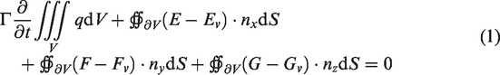
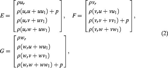
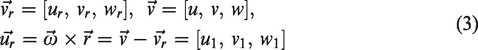
Here, Γ is the preconditioning matrix, q is the primitive component of u, v and ω. n is the direction vector of S. E, F and G termed vector of convective fluxes are related to the convective transport of quantities in the fluid. Ev, Fv and Gv termed vector of viscous fluxes contain the viscous stresses τij. In the formula,
Structural dynamic equations
The finite element method (FEM) formulations can be established on the basis of the finite deformation theory. Assuming that the composite material of nano rotor is linearly elastic and orthotropic, by taking into account the three loads, the corresponding kinetic equation of nano rotor can be written as follows.
29

Fluids–structure interaction method
A loose-coupling method is used in the FSI simulation. Because the FEM mesh is different from the CFD mesh, the data shall be transferred at the interface. In this paper, a RBF-based

The basis function based


In this paper, the r0 is defined as 0.1 R so that less control points are required.

The deforming grid method is used in the CFD solver. In the paper, MRF method was verified by comparing with the experiments from Bohorquez et al.,
15
the rotor is a nano rotor with straight blade. By changing the angle of attack (α) at the rotational velocity of 10,000 r/min, we calculated the propulsive performance of the nano rotor and compared with the experimental results as shown in Figure 1. Results showed that the computational results match well with the experimental results except at two small angles of attack. It is considered that it is because of the experimental error since the thrust and torque of the nano rotor are very low at the low angle of attack so that is not easy to measure them. Therefore, MRF method can be used in the study and the computational model is considered reliable. The preconditioned Roe scheme is reconstructed with using the Roe-averaged values in this computation. For the preconditioned system, a LUSGS-τts dual time-stepping scheme is employed by introducing a pseudo time-derivative with preconditioning matrix. With the preconditioning method, the numerical flux and dissipation item in the x direction is written with primitive variables as

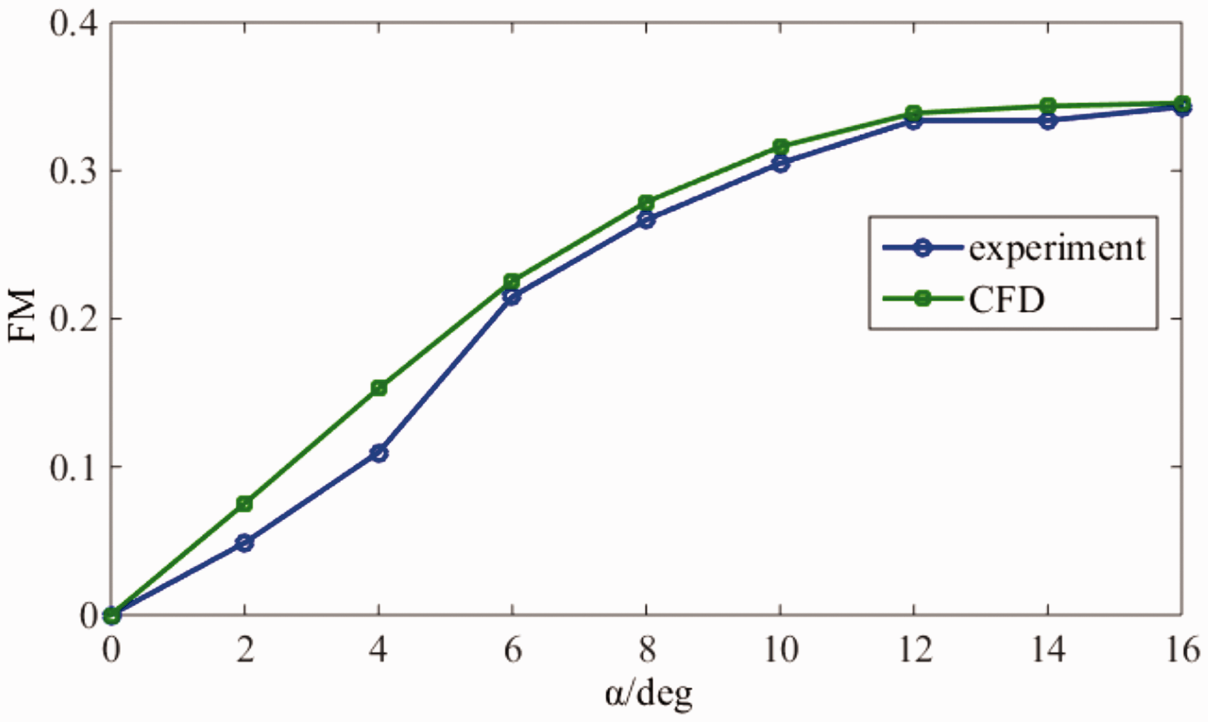
α vs. FM at 10,000 r/min for nano rotors.
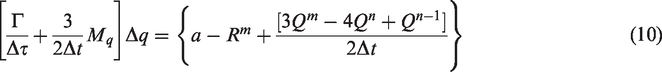
The governing equation is discretized in an implicit mode with a three-point backwards difference in time as follows.
Because of the introduction of preconditioning technique, the dual-time-stepping scheme might be written with the matrixes L, D and U.

Hereafter, the preconditioning parameter can be controlled by the pseudo time. When
Bio-inspired pitch motion
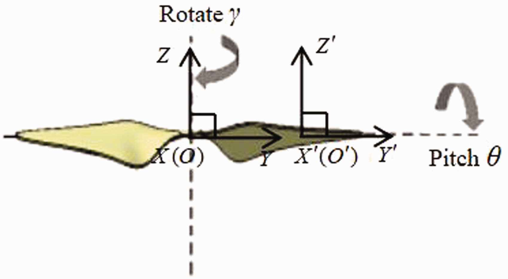
Figure 2 shows a schematic of the motion for the nano rotor. Two blades rotate around the central axis and pitch around the 1/4 chord along the blade. To describe the motion of the nano rotor, two coordinate systems are introduced. The first coordinate system O – XYZ is an inertial coordinate system which keeps motionless and the other coordinate system

Blades chord and twist distribution of nano rotor.
The rotational speed of the nano rotor is 6500 r/min. Then, the pitch motion of the blade is defined as a sine function

Modal test experimental setup
A nano rotor with diameters of 7.5 cm was designed based on low Reynolds number aerodynamics and minimum induced loss theory to minimize energy loss. The rotor has a mean chord c of 0.31 R as shown in Figure 3. Traditional contact-type modal test method cannot be adopted because extra mass and stiffness will be introduced. In this study, a non-contact modal experiment platform for nano rotor was established based on sound excitation instrument and laser vibrometer as shown in Figure 4. This test platform includes supporter of the nano rotor, sound excitation instrument, and laser vibrometer. The full frequency speaker was excited by broadband white noise signal, which was also input into the Polytec laser vibrometer system as a reference signal. The SPL of the sound generated is from 100 to 110 dB. A two-dimensional modal test was performed for the rotor. Seventy to eighty laser scanning points were set on the surface of nano rotor and their vibration displacements were measured by virtue of Doppler Effect. All the measured signals were processed to filter the useless signals and reduce the noise so as to ultimately obtain the accurate frequency spectrum and vibration modes of nano rotor.

Schematic of rotor size and shape.

Modal test bench for nano rotor.
Results and discussion
Dynamic characteristics analysis of nano rotor
The nano rotor used for the computation modal test was laminated by a six-layered unidirectional fibre composite, and the stacking sequence in Figure 5 was [0/90/0/90/0/90]. The hexahedron mesh was used for the structure dynamics and the elements were liner C3D8I. The thickness of each layer was

FE model of nano rotor.
When comparing the experimental results and computational results, it is found that the two groups of vibration modes are extremely similar in flapping, bending, and torsion according to the similar vibration modes. The corresponding natural frequencies are also compared in Table 1. It is found that the relative errors for them are lower than 4%. The first two natural frequencies are also comparable to the rotating frequency of the nano rotor, which shall be paid more attention to during the design of the NAV to avoid the resonance. Because the maximum relative error of simulation is lower than 4% and the minimum relative error is even lower than 1%, the finite element model is thought to be capable of reflecting the main structural feature of nano rotor.
Comparison of natural frequencies between experiment and computation.

Propulsive performance of bio-inspired rigid nano rotor
MRF is used to describe the rotation and the pitch motion in this study. The flow field is composed of a static block, a rotation block, and a pitch block as shown in Figure 6. An unstructured grid is used in moving block and a structured grid is used in the static region. The pitch block which contains two blades is a cylinder with a radius of

Computation zone of rotor for CFD.
The rotational speed of nano rotor is 6500 r/min and the rotation frequency of the rotor is f0. Three cases are calculated including case 1 in which there is no pitch motion, case 2 in which the pitch frequency
Figure 7 shows the thrust and the torque of the nano rotor varying with the azimuth. It is found that the curves of thrust and the torque resemble sine or cosine function. And the periods of the curves corresponds with that of the pitching motion. The frequency of the curve increases with the pitching frequency. The amplitude of the thrust and torque increases with the frequency as well. For the non-pitching case, the value of the thrust and the torque keeps as an equilibrium value.

Lift and torque curves of pitching rigid rotor in one cycle (a) thrust and (b) torque.
In order to describe the propulsion performance of the rotor more intuitively and quantitatively, FM is applied for the analysis. It is a certain ratio between the rotor thrust coefficient and the power factor (also called torque coefficient). The simple thrust coefficient and power factor are difficult to objectively describe the performance of the rotor in terms of energy utilization. Therefore, the FM is used to measure the hovering efficiency of the rotor. It is shown as follows.

The average value in a cycle for the thrust coefficient, the torque coefficient, and the FM are summarized in Table 2. It is found that the thrust coefficient increase with the pitching frequency. The non-pitching case obtains the minimum FM. And the maximum FM is achieved by the pitching case with high pitching frequency. It is indicated that the propulsive performance of the nano rotor is improved with the bio-inspired pitching motion.
Propulsive performance for different cases.

FM: figure of merit.
Figure 8 shows the pressure coefficient varying with chord at the sections of
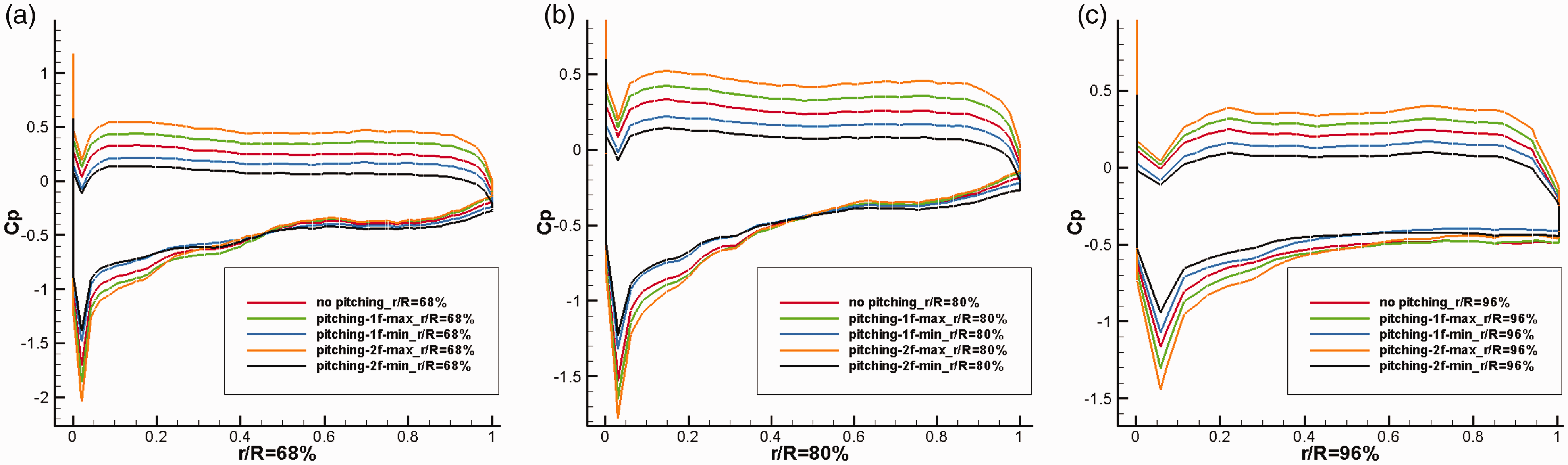
Comparison of pressure coefficient curves among different cases at blade stations: (a) r/R = 68%, (b) r/R = 80% and (c) r/R = 96%.
Figure 9 shows iso-surface and shear layer of the magnitude of vorticity when the lift is maximum. At high pitching angle, the biggest iso-surface is shown, which indicates that the vorticity is the strongest. The pitching motion influences the vorticity and propulsive performance of the nano rotor as a result.
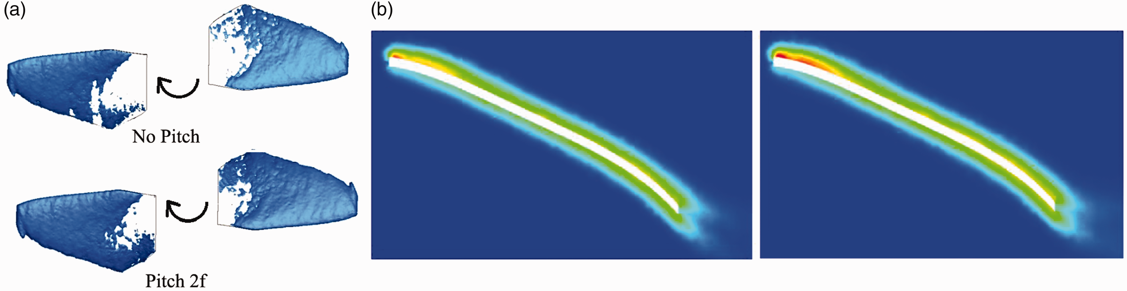
Iso-surface (a) and shear layer (b) of vorticity for the non-pitch and the pitching nano rotor.
Propulsive performance of bio-inspired flexible nano rotor
The bio-inspired flexible nano rotor with pitching frequency of

Thrust and torque varying with the azimuth for both flexible and rigid nano rotor (a) thrust and (b) torque.
Propulsive performance for flexible and rigid nano rotor.
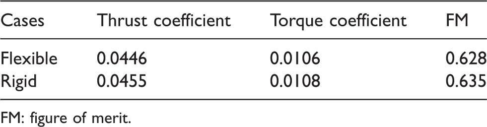
FM: figure of merit.
Figure 11 shows the pressure coefficient at different blade stations for both flexible and rigid bio-inspired nano rotor when the rotor achieves the maximum thrust coefficient. It is found that the curve of the pressure coefficient for the flexible nano rotor nearly locates inside of that for the rigid nano rotor at all the blade stations except at
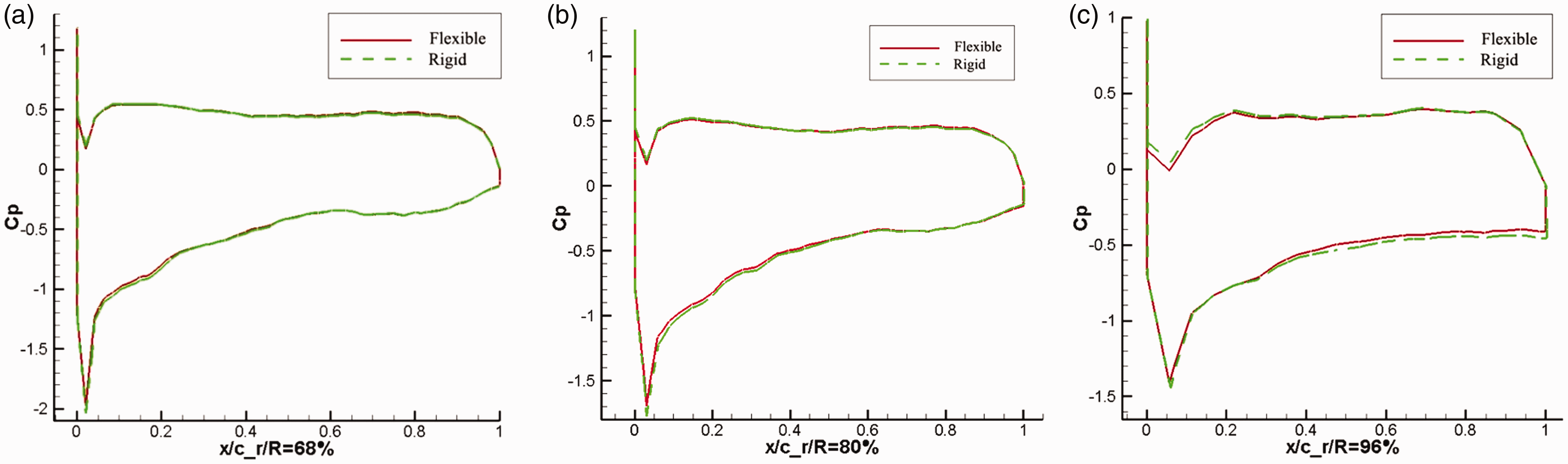
Thrust and torque varying with the azimuth for both flexible and rigid nano rotor (a) r/R = 68%, (b) r/R = 80% and(c) r/R = 96%.
Structural response of bio-inspired flexible nano rotor
Figure 12 shows displacement and stress contour of the nano rotor. At the beginning, the maximum displacement vibrates irregularly. The maximum amplitude is as high as 0.2 mm. Then, it begins to vibrate regularly. Results show that the maximum of the displacement is about 0.118 mm at the blade tip. The maximum stress is found at the blade root. The two blades tilt due to the aerodynamic force.

Displacement and stress contour of the nano rotor (a) displacement contour and (b) stress contour.
The amplitude spectrum of displacement at the blade tip is shown in Figure 13. There are two peak values at frequency of 211.9 Hz and 605.46 Hz. When comparing with the modal test results, it is found that the first frequency is close to the rotational frequency. And the second frequency is close to the fundamental frequency of the nano rotor.

Amplitude spectrum of the displacement at the blade tip.
Conclusion
In this paper, the bio-inspired composite nano rotor is studied with FSI method. Blade pitch motion is introduced to improve the propulsive performance of the nano rotor performance. A non-contact modal experimental platform is firstly established using sound excitation instrument and laser vibrometer. The structural characteristics of the composite nano rotor are measured. It is found that the natural frequencies are very close for the first two orders. The finite element model of composite rotor is created accordingly. The model is studied computationally with FEM solver. It is found that the simulation results match well with the experimental results which verified the correctness of the finite element model. The CFD model is established and the propulsive performance of the rigid bio-inspired nano rotor motion is studied at different pitch frequencies. Results show that the thrust and torque for the bio-inspired pitching rotor are higher than those for the rotor without bio-inspired motion. And the propulsive performance for the nano rotor with bio-inspired pitching frequency of two times of that rotation frequency is higher than that with only one time pitching frequency. It is evident that the improvement enhanced with the increase of the pitching frequency. The flexible bio-inspired nano rotor is then investigated with FSI method. The results show that the propulsive performance of the flexible nano rotor is lower than that of the rigid nano rotor. It is evident that it is necessary to consider the flexibility of the composite nano rotor when investigating the propulsion performance of bio-inspired nano rotor. Then, the response of blade structure is also analysed. The results show that the blade structure vibrates at small amplitudes.
In general, it is found that the bio-inspired pitching motion can improve the performance of nano rotor. In the future, the experiment will carry out to verify the computational results.
Footnotes
Declaration of conflicting interests
The author(s) declared no potential conflicts of interest with respect to the research, authorship, and/or publication of this article.
Funding
The author(s) disclosed receipt of the following financial support for the research, authorship, and/or publication of this article: The authors are grateful for the support from the National Natural Science Foundation of China through grant numbers 11772252 and 11302164. The authors also acknowledge the support of K. C. Wong Education Foundation.