
Abstract
Quad-Plane UAV(quadrotor fixed-wing hybrid vertical take-off and landing Unmanned Aerial Vehicle) is vulnerable to wind disturbance in quadrotor mode, and the performance of the electric quadrotor system directly affects its wind disturbance rejection performance. To study and optimize the wind disturbance rejection performance of the electric quadrotor system of Quad-Plane precisely and efficiently, a dynamic electric quadrotor simulation system integrating high-precision submodels of electric quadrotor system components is required. However, there are few papers on this kind of simulation system. This paper proposed a simulation system with both high computational efficiency and precision, and it can be used in optimization and flight simulation of Quad-Plane. The simulation system includes submodels of rotor, brushless direct current (BLDC) motor, electronic speed controller (ESC), and Li-ion Polymer battery. The surrogate-based rotor model is established to calculate the aerodynamic performance of the rotor in oblique flow. The BLDC motor performance calculation model considering inductance is presented and the power loss of the ESC is considered. The discharge characteristics of the battery are modeled considering the rate capacity effect. All submodels are validated and the simulation results show good agreements with test data. A flight test of Quad-Plane in quadrotor mode is conducted to validate the integrated dynamic simulation system. The results show that the simulation system has the advantages of high computational efficiency and precision. Based on the simulation system, the influence of the electric quadrotor system parameters on the performance of the electric quadrotor system, and furthermore on the wind disturbance rejection performance of the Quad-Plane are found, the conclusions are helpful to the selection and optimization of the electric quadrotor system components.
Keywords
Introduction
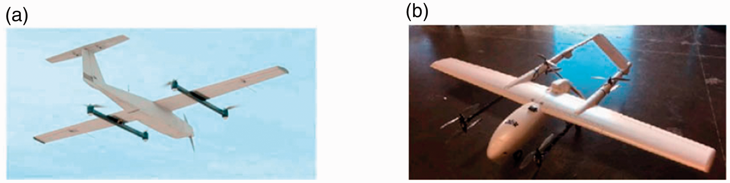
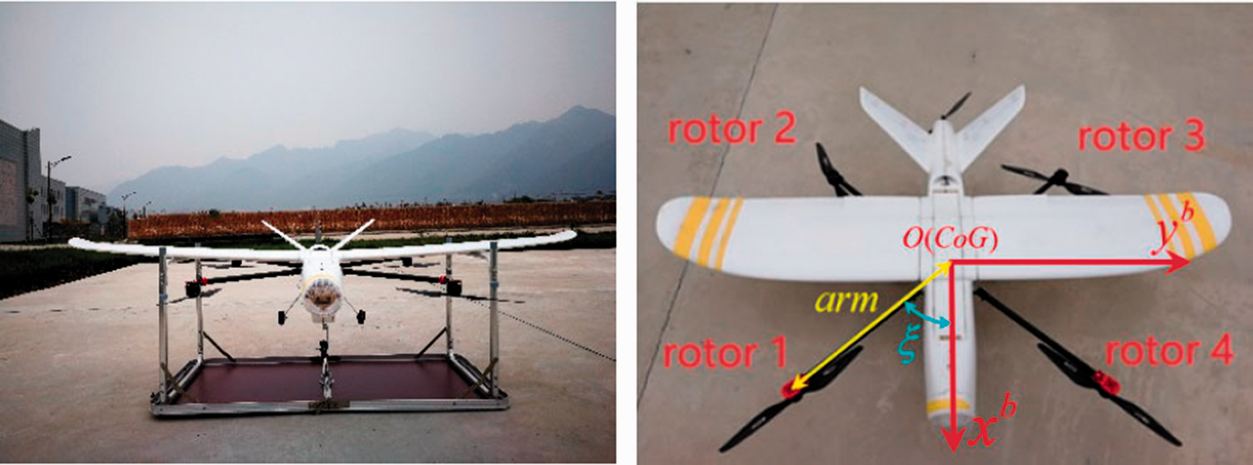
Quad-Plane (quadrotor fixed-wing hybrid vertical take-off and landing Unmanned Aerial Vehicle) is a kind of unmanned aerial vehicle combining the advantages of fixed wing UAV and multi-rotor UAV, as shown in Figure 1. The Quad-Plane takes off in quadrotor mode on the ground, after rising to a certain altitude in quadrotor mode, the propeller mounted at the rear of the fuselage is initiated as the quadrotor system is switched off then the Quad-Plane enters fixed-wing mode and acts as fixed-wing UAV. Because the aerodynamic shape of the Quad-Plane is more complex than that of the multi-rotor and fixed wing UAV, the wind can cause a complex disturbance to the Quad-Plane, thus the Quad-Plane is vulnerable to wind disturbance in quadrotor mode and it is an important factor restricting its large-scale applications.
To analyze wind disturbance rejection performance in the design of Quad-Plane, Zhang et al. 3 conducted a static equilibrium analysis of the quadrotor mode in wind disturbance, it ignored the important dynamic behavior of the Quad-Plane in wind disturbance. So, in order to obtain a more comprehensive understanding of the dynamic response of Quad-Plane in wind disturbance for the better design of such kind of UAV, it is necessary to study the wind disturbance rejection performance of the Quad-Plane through dynamic flight simulation.
The electric quadrotor system drives the Quad-Plane to take-off and land vertically, so the performance of the electric quadrotor system directly affects the wind disturbance rejection performance of Quad-Plane. In order to study and optimize the wind disturbance rejection performance of the electric quadrotor system, a dynamic simulation system of the electric quadrotor system integrating high-precision submodels of electric quadrotor system components is required. However, there are very few articles on this kind of high-precision integrated dynamic simulation system.
The electric quadrotor system is composed of the rotor, BLDC motor, ESC, and Li-ion Polymer battery.
The rotor model used in flight simulation is mainly based on blade element-momentum theory, which can calculate the thrust and torque of the rotor with acceptable accuracy when the rotor receives mainly axial flow—the flow is nearly perpendicular to the rotor rotational plane.4–6 However, when the Quad-Plane is subject to wind disturbance, the direction of wind disturbance is approximately parallel to the ground in most engineering applications, and the rotor receives the influence of the oblique flow and will also generate non-negligible forces and moments in rotational plane.5,7,8 In order to calculate the aerodynamic performance of the rotor in such an oblique flow in flight simulation, an accurate and efficient method is required.
As the main power source of current electric UAVs , BLDC motors have been widely used in Quad-Planes due to their high reliability, long life, minimal maintenance requirements, excellent controllability, and wide speed range. In the flight simulation on UAV, the influence of inductance is often ignored in the modeling of the BLDC motor, leading to the significant error of the calculated BLDC motor performance such as torque and current.9–12 Inductance is the parameter that has a significant influence on BLDC motor performance,12–14 especially for BLDC motors with a large number of poles and power. Although the BLDC motor can be simulated by finite element numerical simulation to achieve a high-precision model, 14 a lot of detailed information of the motor is required, this will greatly reduce the efficiency of flight simulation and design of Quad-Plane. So, it is necessary to obtain an efficient and high-fidelity model of the BLDC motor.
The ESC converts the direct current (DC) electricity from the battery to alternating current (AC) to drive the BLDC motor. It receives the throttle command from the flight control system and adjusts the motor speed by changing the duty cycle length, and the main types of losses of ESC are conduction losses due to the resistance and switching losses due to the commutating time. The current efficiency of ESC is generally above 90%.15–17 Lindahl et al. 18 ignore the power loss caused by ESC, and Budinger et al. 19 ignore the switching losses of ESC. Only a few models for ESC exist and the performance data available for ESC is scarce.10,16,20
According to existing articles,21–23 the battery model can be divided into categories as the electrochemical model, intelligent mathematical model, and the equivalent circuit model in terms of different mechanisms. Considering the accuracy and time consumption of the simulation, the equivalent circuit model is adopted in this paper, which has a clear physical meaning and simple expression.
At present, the electric quadrotor system components are selected from off-the-shelf products based on experience. There are a large number of manufactures for electric quadrotor system components, especially for BLDC motors, and statistical data show that due to the differences in manufactures, design concepts, or manufacturing methods, etc., there are significant differences in parameters among various components.11,24–26 For example, BLDC motors with the same power and speed constant often have different parameters, such as internal resistance and inductance. Researchers of electric UAV always care about what kind of specifications is better among candidate electric quadrotor system components with similar specifications. Therefore, it is necessary to study the influence of these parameters on the performance of the electric quadrotor system for optimal electric quadrotor system design.
The main purpose of this paper is divided into two parts. The first is trying to propose a high-precision integrated simulation system of the electric quadrotor system, another is trying to find out the influence of small changes in macro specifications such as resistance, pole pairs on electric quadrotor system, and on the wind rejection performance of Quad-Plane.
In this paper, the high-precision integrated simulation system of the electric quadrotor system is proposed for the first time, including the modeling of the rotor, BLDC motor and ESC, and battery. Based on this simulation system, the wind disturbance rejection performance of the electric quadrotor system which is equipped on the target Quad-Plane against different types of wind disturbance is studied. Moreover, to improve the wind disturbance rejection performance of the Quad-Plane in the quadrotor mode, the influence of the parameters of the electric quadrotor system on the steady-state and dynamic performance of the electric quadrotor system, and furthermore the influence of them on the wind disturbance rejection performance of the Quad-Plane are studied.
Modeling and validation of electric quadrotor system components
This section describes in detail the modeling and validation of electric quadrotor system components, including the surrogate-based rotor model in oblique flow, BLDC motor and ESC model, and dynamic battery discharging model.
Surrogate-based rotor model
Method
The flow around the rotor is simulated by solving the unsteady Reynolds-Averaged N-S equation. This method has been validated and used in aerodynamic analysis of the hover 27 and forward flight28,29 condition of tilt rotors, and the oblique flow condition of the blade.7,30
The governing equation is described as


The

Hybrid structured–unstructured mesh of computation field. (a) Static zone. (b) Rotational zone.

Grid near the wall of the rotor.
Validation
To validate the Computational Fluid Dynamics (CFD) method, this paper first calculates the steady-state thrust and torque of the 16-inch rotor used in the Quad-Plane and compares the results to the test data.
The test environment is shown in Figure 4. The test system is shown in Figure 5. A DC power source is used to supply energy, and a 40 A ESC is used to drive the BLDC motor. The MINI balance of ATI company is used for thrust and torque measurement. In order to acquire data from the test system, a measurement system using National Instruments (NI) LabVIEW virtual instrumentation has been utilized: a CDAQ-9174 device with two compact DAQ modules including NI 9205 and NI 9401. The analogue voltage output from the six degrees of freedom (Dof) balance is acquired by the 16 bit Data Acquisition card NI 9205 at a sampling rate of 1000 Hz, and the collected signals are converted into the thrust and torque data. Meanwhile, the NI 9401 module counts the rotational speed laser sensor analogue output pulses and converts them into propeller rotational speed. The electric currents and voltage of the DC power supply applied to the BLDC motor are also recorded, which can be used to calculate the power input of the BLDC motor.

Test environment of the rotor.

Test system hardware and data flow of the test system.
Figure 6 shows the steady-state thrust and torque of the rotor at different rotation speeds. The calculated results are in good agreement with the test results. The mean error of thrust is 4.45%, and the maximum error is 6.54%. The mean error of torque is 0.98% and the maximum error is 1.34%.
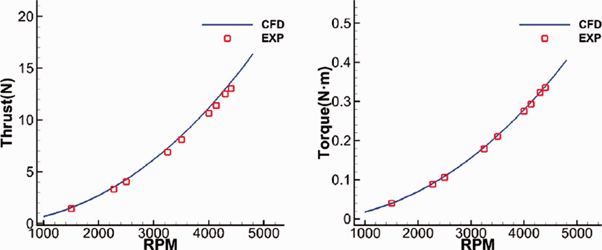
Comparison between the experimental results and the calculated results of the steady-state performance of the T-motor16 × 5.4 rotor.
Surrogate-based model of rotor
When the Quad-Plane works in quadrotor mode, the flow velocity of wind disturbance near the ground will be approximately parallel to the rotor rotation plane, so there is a relatively large oblique inflow angle

Coordinate system of the rotor, inflow
With the increase in oblique inflow angle

Forces during one rotation period at different oblique inflow angles. (a) X direction. (b) Y direction. (c) Z direction.
Figure 9 shows the moments in one rotation cycle with different oblique inflow angles

Moments during one rotation period at different oblique inflow angles. (a) X direction. (b) Y direction. (c) Z direction.
The average of the forces in the X and Y directions in a rotation cycle is much smaller than that in the Z direction, but the moments in the X, Y, and Z directions are of the same magnitude. Thus, the forces in X and Y directions are ignored in the modeling, and force in the Z direction and moments are taken into consideration when modeling the rotor in oblique flow. Moreover, although the forces and moments of the rotor are periodic with the azimuthal angle, the period is very short and only 0.01 s at 4000 r/min. As a result, the periodic forces and moments are time-averaged in rotor modeling.
As Quad-Plane suffers from wind disturbance, the aerodynamic forces and moments of the rotor are complicated affected by wind speed, oblique inflow angle, and rotor speed. Hence, in the simulation model, the forces and moments generated by the rotor are expressed as

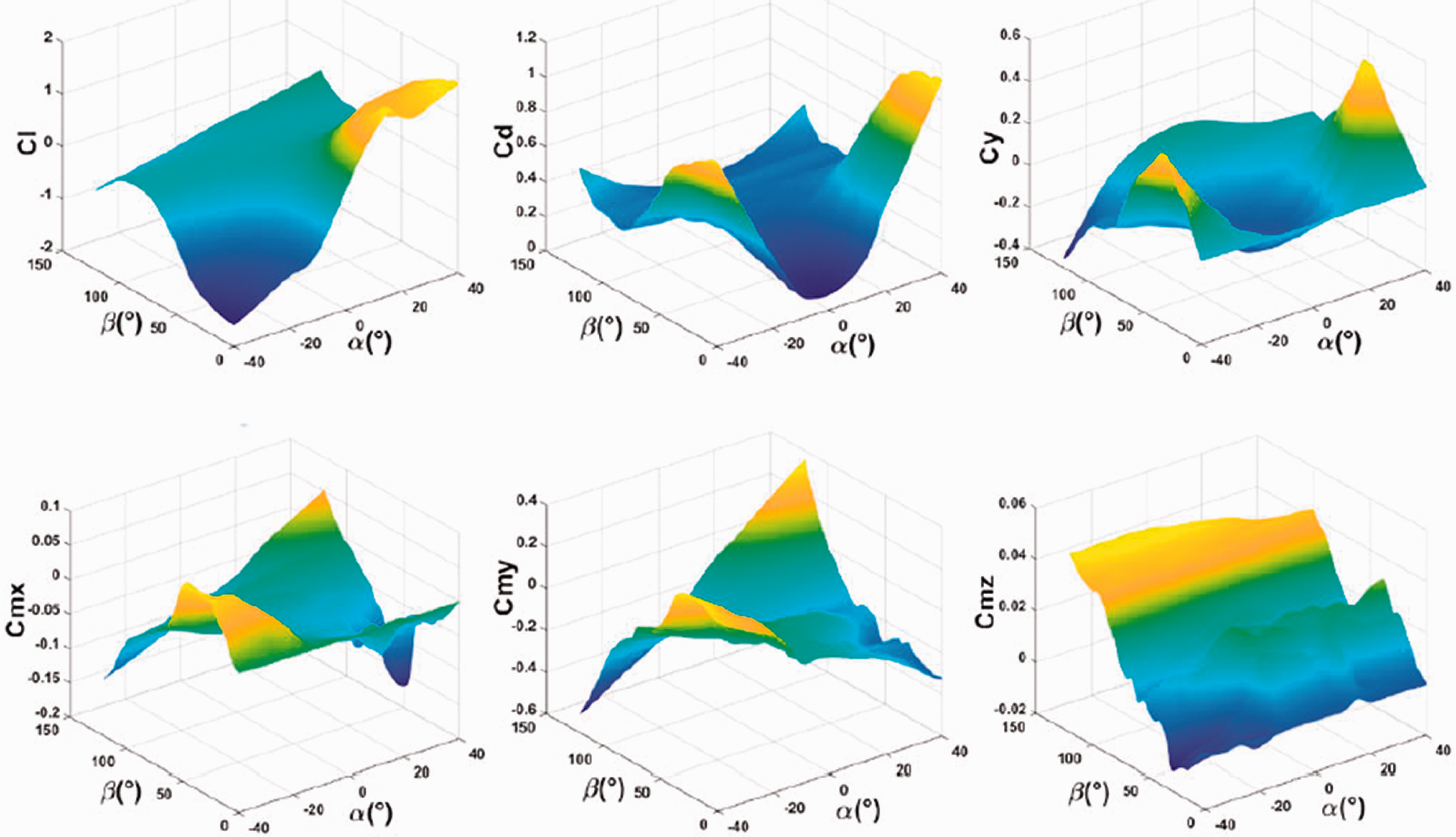
In flight simulation, the aerodynamic forces and moments of the rotor should be calculated rapidly based on these independent variables. So, the surrogate model is adopted to establish the rotor model. The surrogate model plays an important role in different areas of aerospace science and engineering, and can be used to greatly improve the modeling efficiency when high-fidelity but time-consuming numerical models such as CFD analysis33,34 are employed. In order to study the feasibility of the application of the surrogate model, the aerodynamic performance of the rotor with the change of wind speed, rotation speed, and oblique inflow angle is studied. If the aerodynamic performance shows regularity with those variables, modeling will require very few sample points while achieving high-fidelity. Therefore, the CFD analysis for the rotor performance in different working conditions is conducted, including the different magnitude of inflow speeds to the rotational plane, oblique inflow angles, and rotation speeds. The results are shown in Figure 10. The aerodynamic characteristics of the rotor in different conditions show a strong regularity with the change of rotation speed. This is ideal for modeling with the surrogate model.
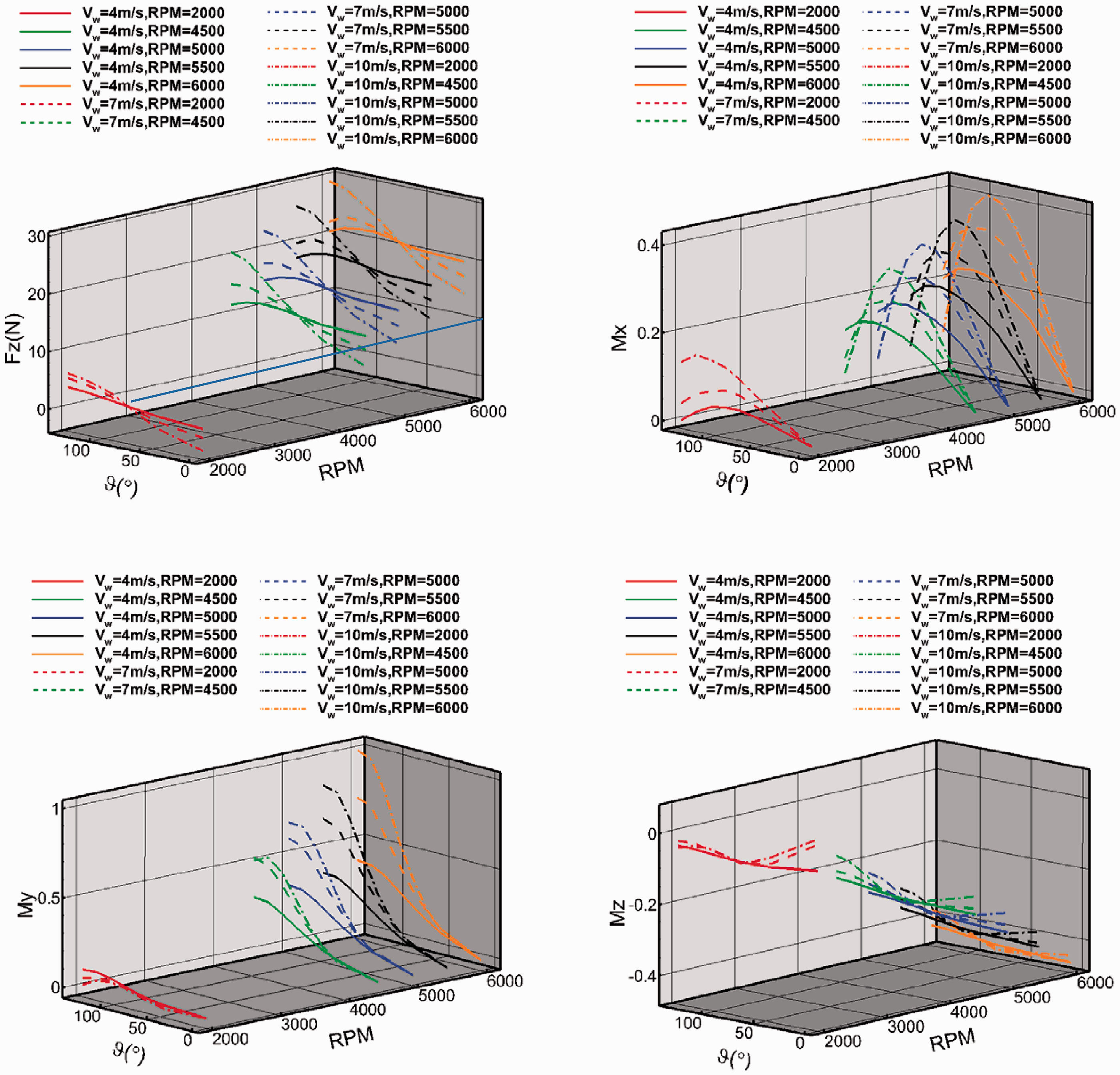
Aerodynamic characteristics of rotor at different rotation speeds, oblique inflow angles, and wind speeds.
The surrogate-based model of the aerodynamic performance of rotor including forces and moments at different wind speeds, RPMs, and oblique inflow angles is established. The kriging model in Design and Analysis of Computer Experiments (DACE)
35
is used to build the surrogate model of rotor. The kriging model is of the form

The range of each variable is

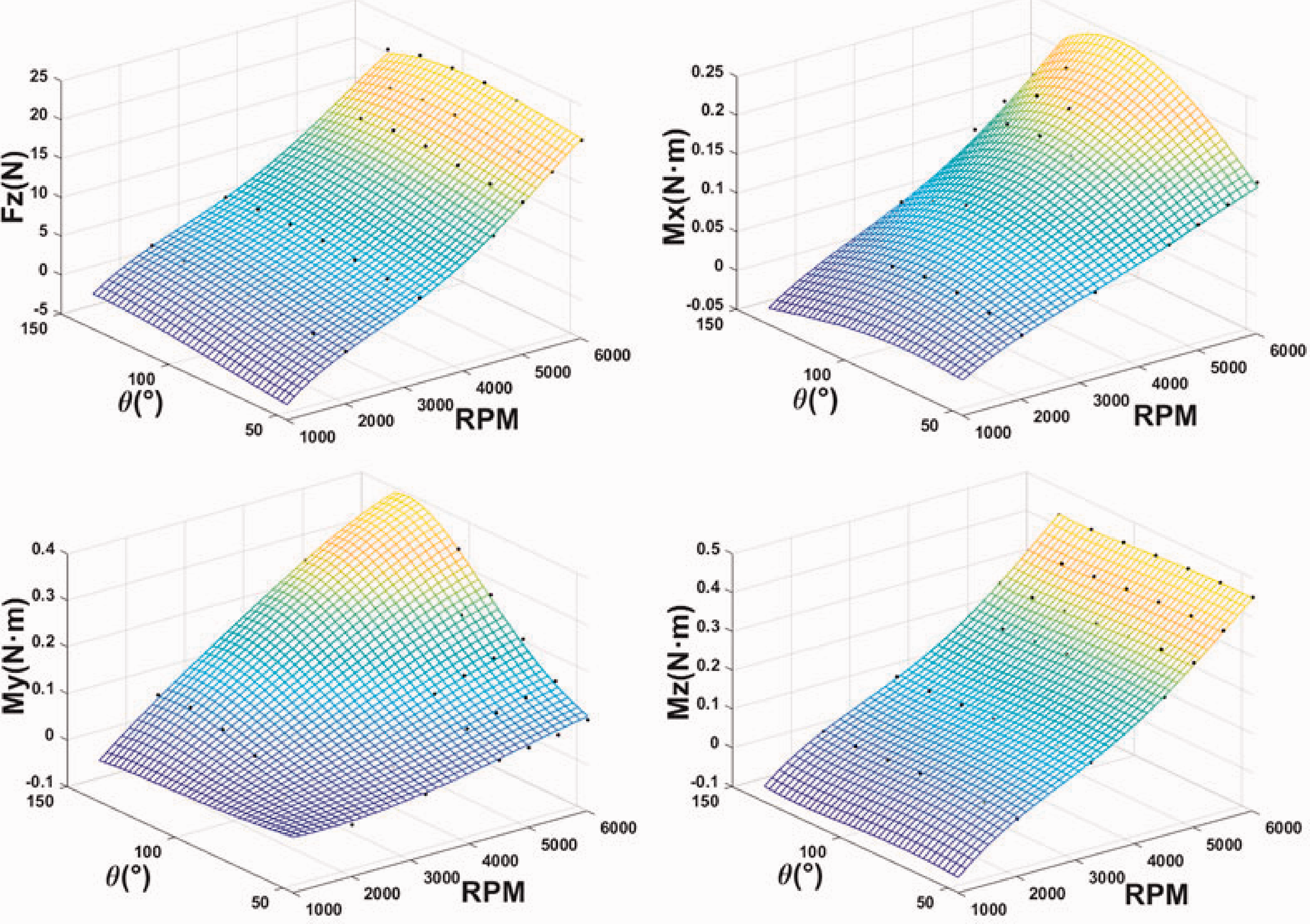
Results of motor model at wind speed of 4 m/s where black dots denote the CFD results at 4 m/s.
MSE of motor model.

Brushless direct current motor and electronic speed controller model
Method
BLDC motor is essentially a permanent magnet synchronous motor system that consists of the permanent magnet motor module, current control module, position detection module, speed control module, torque calculation module, voltage inverter module, etc. Hence, considering its physical nature, the model should include all the submodules mentioned above. But in the electric quadrotor simulation system, it is unnecessary to pay too much attention to the detailed transient information of the brushless DC motor, such as switching frequency and torque ripple. Meanwhile, too complex models have negative influences on computation efficiency. Since the behavior of the BLDC motor can be considered as a DC motor, the BLDC motor can be modeled as a DC motor36–38 model which can be expressed by mathematical polynomials. To calculate the torque and current of the BLDC motor at specific speeds and throttles more precisely, the inductance should be considered. The detailed derivation of the calculation method is in articles.39,40 Inductance has an obvious influence on the electromagnetic time constant of the motor, which is defined as

The conduction time span of a single phase of BLDC motor can be defined as

The ratio between 
The current and torque of the BLDC motor are periodic, but the measured current and torque are time-averaged. By means of the ratio x and some other variables, the time-averaged current iav and torque Tav can be calculated as


For the three-phase, Y-connected BLDC motor, 


In the light of the engineering case for Quad-Plane, the power loss of ESC can be interpreted as the efficiency
41

And the relationship between battery voltage 

Validation
To validate the model, the BLDC motor model with and without 42 considering inductance are respectively used to calculate the current and torque of two BLDC motors, T-motor U5-KV400 43 and T-motor U11-KV90. 44 Parameters of these motors are shown in Table 2.
Parameters of BLDC motors.

The torque and current of U5-KV400 and U11-KV90 at different speeds are calculated by using the model with and without inductance considered and are compared with the test results that is acquired by using the experiment setup mentioned in the Validation of the Surrogate-based rotor model section. The results are shown in Figures 12 and 13. When the inductance is not considered, the mean errors between calculation result and test result of torque of U5 and U11 are 27.3% and 14.9%. After taking the inductance into account, the mean errors decrease to 10.74% and 5.77%. The same trend occurs in the current calculation that when the inductance is considered, the mean errors between calculation results and test results of torque of U5 and U11 decrease from 40.9% and 25.2% to 22.3% and 13.3%, which demonstrates that the inductance plays an important role in BLDC modeling. Meanwhile, there are still some deviations that exist between calculation results and test results when considering inductance, the reason can be explained as follows. First, the increase in current leads to the temperature rise of the motor winding, which will increase the resistance value. In addition, the magnetic circuit saturation phenomenon occurs during the operation of the motor, resulting in inductance changes. 45 These are beyond the scope of this paper.

Comparison of U5-KV400 motor performances by different calculation models.

Comparison of U11-KV90 motor performances by different calculation models.
Dynamic battery discharging model
Method
The electrical equivalent circuit of the battery model is shown in Figure 14. It consists of an open circuit voltage

Second-order equivalent circuit model.
According to Figure 14, based on Kirchhoff laws


Based on equations (18), (20), and (21)

The output voltage of the battery can be calculated as


The battery SOC can be expressed as


Validation
A battery with its model parameters identified is used in validation.
23
The capacity of the battery is 2.5 Ah, and the simulation includes two parts. First, the constant-current discharging processes with the discharging current of 1.25 A and 2.5 A are simulated, then the dynamic discharge process with the variable discharging current is simulated. The variable current is the function of time and can be described as
23

The model coefficients of the battery are defined as
23

Both discharging simulation results are compared with test data, 23 the comparison is shown in Figure 15. The results show good agreement with test data, the mean and maximum errors of each comparison are shown in Table 3, which indicates that the model can describe the discharging process with the variable discharging current, and constant current.

Comparison between simulation results and test results of the battery voltage in (a) constant-current discharging and (b) variable-current discharging.
Mean and maximum errors of the comparison between simulation and test results of the discharging with constant and variable current.

Discharge model of 6S-10 Ah battery
In this section, the model of a 6S-10 Ah battery which is used in the electric quadrotor system is established, the model coefficients are obtained by numerical optimization based on discharging data of the example battery
23
and the data provided by the battery manufacturer TATTU of 10 A and 30 A. The feasibility of numerical optimization is based on the similar characteristics and discharging mechanisms among different Li-ion battery, and this paper is not focussed on the physical and chemical characteristics of the battery, so the parameters of the battery model can be obtained by mathematical optimization method. The model coefficients of the battery are defined as
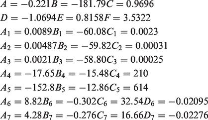
Figure 16 displays the comparison between measured data and simulation results of a TATTU 6S-10 Ah battery discharging process in 10 A and 30 A conditions. During discharging, when the battery discharges with 10 A and 30 A respectively from the initial voltage of 25.2 V to the cut-off voltage of 19.2 V, the total discharging capacity both exceeds 10 Ah. The simulation results show good agreements with the test data, the mean and maximum errors of each comparison are shown in Table 4. Meanwhile, as the discharge current increases, the amount of the battery capacity decreases. The battery model also shows exactly this phenomenon.

Comparison between simulation results and test results of TATTU 6S-10 Ah battery voltage in constant-current discharging.
Target Quad-Plane.
Mean and maximum errors of the comparison between simulation and test results of the discharging of the TATTU 6S-10 Ah battery.

Parameters of target Quad-Plane.

Simulation of dynamic response of the electric quadrotor system in wind disturbance
Target Quad-Plane
The dynamic wind disturbance rejection performance of the electric quadrotor system is simulated in this section. The electric quadrotor simulation system is embedded in the Quad-Plane flight simulation system. A Quad-Plane with take-off weight of 5 kg is taken as an example, as shown in Figure 17. The main parameters are shown in Table 5. The electric quadrotor system is composed of four U5-KV400 BLDC motors, four 16-inch rotors, four Hobby-wing 40 A ESCs, and a 6S-10 Ah battery. The quadrotor mode controller is the Pixhawk with Proportional Integral Differential (PID) technique. Each component of the electric quadrotor system is modeled in the previous section. In this section, the dynamic responses of the electric quadrotor system in 1-cos 46 wind disturbance and Von Karman 47 wind disturbance are simulated respectively. In simulation, the disturbance wind blows from the sideward of the Quad-Plane because based on engineering applications, it is assumed that when Quad-Plane works in quadrotor mode, the crosswind gives Quad-Plane the most severe asymmetric disturbance.
Quad-Plane flight simulation architecture
The entire flight simulation system is composed of several interconnected blocks, as shown in Figure 18.

Architecture of dynamic flight simulation system of Quad-Plane.
“Inputs” acquires the task commands from the remote controller or the routine programmed in advance which include data of desired position and attitude. These commands are transmitted to “Position controller”, the block includes PID 48 control algorithms for position stabilization, compares the commands with feedback position to determine the accelerations. Based on accelerations, the desired Euler angle is solved and these desired Euler angles are transmitted to “Attitude controller” which includes PID 48 control algorithms and output the angular acceleration.
The block “Electric Quadrotor System” includes the dynamic simulation system established in this paper. The inputs are three angular accelerations, the acceleration in vertical height direction, the velocity and angular velocity of the Quad-Plane, and wind disturbance at every simulation timestep. Then the forces and moments generated by electric quadrotor system are outputted to the “Flight Dynamic” block.
The block “Flight Dynamic” includes the six Dof equation of rigid body which represents the physics of Quad-Plane and outputs the flight data such as position, velocity, and acceleration in both linear and angular quantities.
The block “Wind Disturbance” includes the 1-cos gust wind disturbance model and Von Karman wind disturbance model, which receives the position of Quad-Plane as input and outputs the velocity vector of wind disturbance.
The block “Aerodynamic” models the aerodynamic performance of Quad-Plane in the simulation environment, which is composed of high-precision CFD results of Quad-Plane in quadrotor mode by solving the Reynolds-Averaged N-S equation, as shown in Figure 19.
Aerodynamic model used in flight simulation.
The detail of the block “Electric Quadrotor System” is shown in Figure 20. The accelerations are transmitted to the block and the voltage of BLDC motors are determined, and finally transformed to duty cycle through “throttle calculator”, and battery voltage are transmitted into “BLDC motor” as inputs, the duty cycle is used to calculate BLDC motor speed by means of the BLDC motor model, and the battery voltage is used to limit the performance of the BLDC motor. Then the motor speed and torque are determined, the motor torque is used to calculate the current of the motor, then it is transmitted into the “Battery model” to simulate the battery discharge process and calculate battery voltage. The motor speed, disturbance wind speed, and flight data of Quad-Plane are transmitted into “Rotor” as inputs, after adding the wind disturbance velocity to Quad-Plane ground velocity, the true airspeed of Quad-Plane is obtained. The true airspeed vector represents the relative disturbance wind speed to each rotor, through the surrogate-based rotor model, the forces and moments of the rotor can be obtained.

Architecture of “Electric Quadrotor System”.
Validation
A flight test about acquiring the wind disturbance rejection performance of Quad-Plane in quadrotor mode is conducted. The test is intended to be carried out by keeping the Quad-Plane hovering in a wind disturbance environment and observing whether the Quad-Plane is stable or not and measure the disturbance wind speed to determine the maximum disturbance wind speed Quad-Plane can reject. But since it is not easy to find the appropriate wind field to provide disturbance to Quad-Plane, and because the ground speed is easier to be recorded, therefore we control the target Quad-Plane manually to fly sideward in the quadrotor mode to generate relative motion between the windless atmosphere and the Quad-Plane, as shown in Figure 21, and the ground speed is considered identical to the turbulent wind speed because of the windless atmosphere.

Quad-Plane flies sideward in quadrotor mode manually.
The Quad-Plane flies sideward with speed varies from 0 to 5.5 m/s under manual control, the measured speed varies with time is shown in Figure 22, which is also used to input disturbance wind speed in the flight simulation to provide wind disturbance, which guarantees that the simulation environment is identical to the experiment environment.

Wind speed measured in flight test, which is used as disturbance wind speed input in simulation.
The current consumption calculated during the simulation is compared with the experiment result to evaluate the correctness of the electric quadrotor simulation system, as shown in Figure 23. The current consumption of the electric quadrotor system is maximized as speed varies to the maximum at 9.5 s and 16 s. The current consumption of the electric quadrotor system calculated by simulation is in good agreement with that measured by the flight test. This indicates that the electric quadrotor simulation system established in this paper has enough accuracy and can calculate the power consumption of the electric quadrotor system in wind disturbance. The simulation process takes computational time of 0.85 s with Intel core i7-4790k, which shows the computational efficiency.

Comparison between current consumption measured by flight test and that obtained by simulation.
Simulation of electric quadrotor system in wind disturbance environment
1-cos wind disturbance
In the flight simulation, the Quad-Plane is placed on the ground at t = 0 s, and is required to take-off vertically and rise to 20 m height and maintain the position. Simultaneously, a 5 m/s 1-cos crosswind disturbance is generated, blows from the sideward of the Quad-Plane, as shown in Figure 24. The crosswind starts at the beginning of the simulation, accelerates to the maximum speed of 5 m/s during 0.5 s, then maintains the speed, and finally fades away at 20 s.

1-cos crosswind disturbance.
The dynamic response of each rotor, the current consumed by motors, and battery voltage are shown in Figure 25(a) to (c), respectively. At the beginning of the simulation, the throttle of each BLDC motor reaches a high value to rise the Quad-Plane. Meanwhile, the 1-cos crosswind disturbance is introduced into the simulation, the Quad-Plane generates aerodynamic forces and moments and has the trend to be unstable. Then the flight simulation calculates proper duty cycle length for each BLDC motor to adjust the rotor speed to appropriate values in order to generate appropriate forces and moments to offset the influence of crosswind on Quad-Plane to maintain the position and attitude of the Quad-Plane. In this process, fluctuation of rotor speed occurs at the beginning of the simulation. As the attitude adjustment completes, the Quad-Plane maintains its position and becomes stable, the resultant forces and moments act on Quad-Plane are zero. Subsequently, the crosswind speed keeps constant, so the rotation speed of each rotor of the electric quadrotor system is unchanged. As the simulation goes to 20 s, the disturbance wind stops, the Quad-Plane subject only to the effects of gravity and rotors, the BLDC motors adjust their rotation speed to identical values. The variation in the rotation speed influences the variation of current consumption, further influences the battery voltage, as shown in Figure 25(b) and (c). In the process of large current discharge, the battery voltage drops sharply. As the motor current decreases, the recovery effect of the battery causes the voltage to rise slightly.
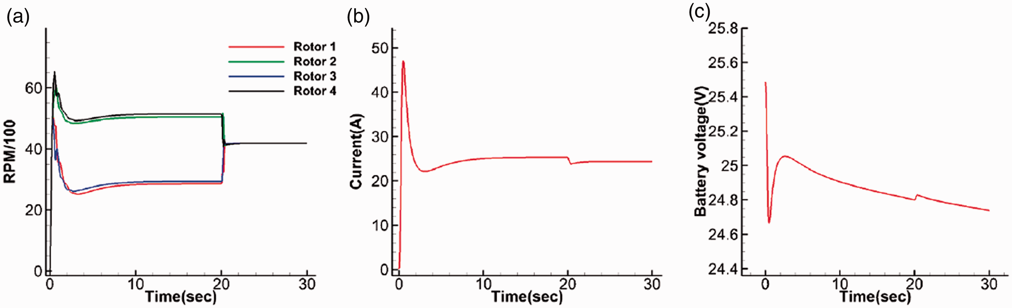
Rotor speed, current, and battery voltage in 1-cos wind disturbance. (a) Rotor speed response. (b) Current consumed by motors. (c) Battery voltage.
If the wind disturbance continues, the Quad-Plane will maintain its position until the battery voltage decreases to the cut-off voltage, which is 21 V in this case. In the simulation, the battery takes 1327 s to discharge until the voltage goes to cut-off voltage, as shown in Figure 26, which means the Quad-Plane can hover for 22.1 min in the 1-cos disturbance wind of 5 m/s.

Simulated battery voltage.
To analyze the wind disturbance rejection performance of the electric quadrotor system that contributes to Quad-Plane, a series of flight simulation cases are conducted with different 1-cos disturbance wind speeds. In each case with different wind speeds, the simulation continues until the battery voltage goes to cut-off voltage, and the hovering endurance in each case is recorded to evaluate the battery performance, the result is shown in Figure 27. The object Quad-Plane can reject 5.82 m/s 1-cos crosswind disturbance with a hovering endurance of 1288 s.
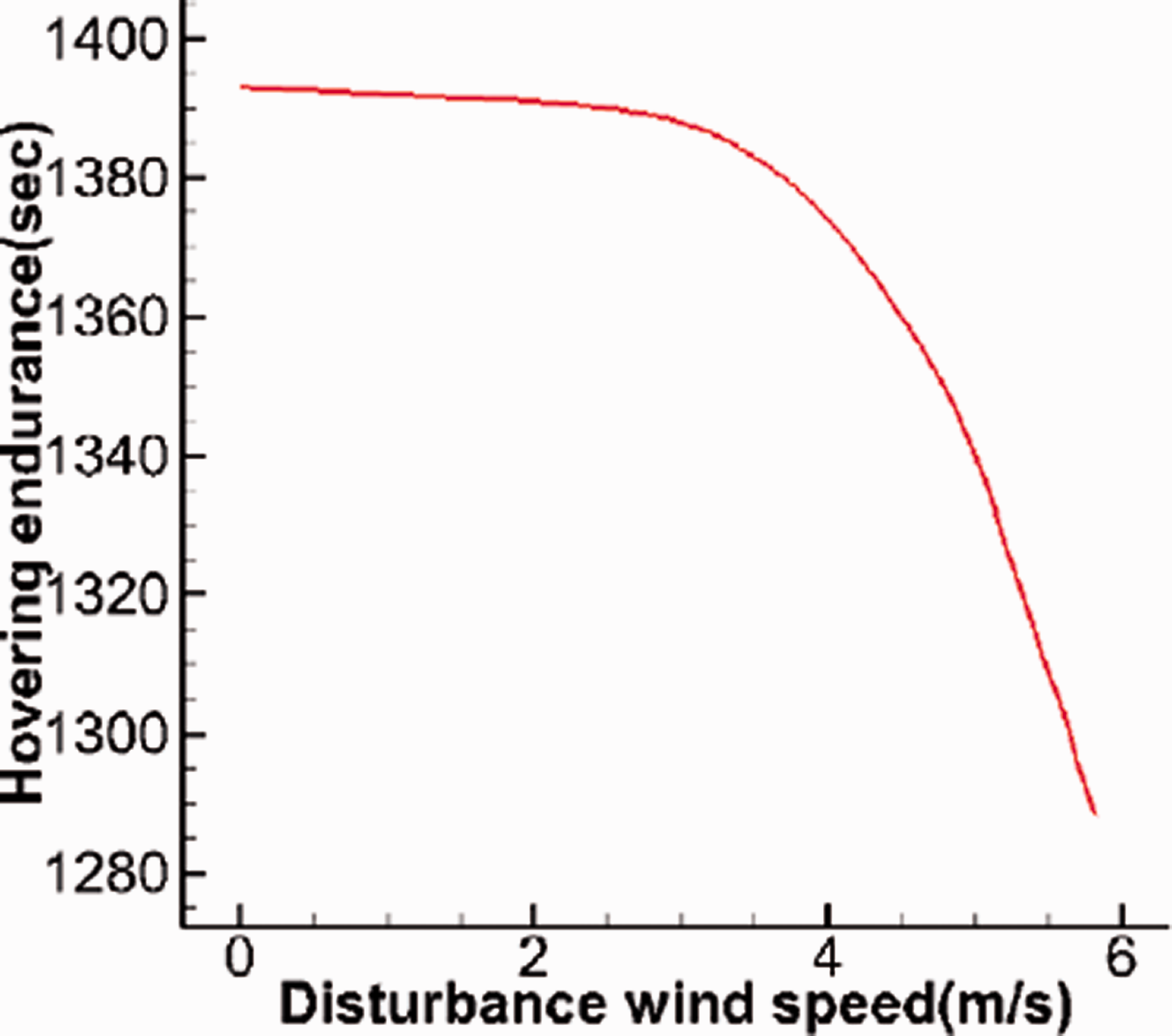
The disturbance wind speed and corresponding hovering endurance.
The variation of the rotation speed of each rotor with time at 3 m/s, 5 m/s, 5.82 m/s, and 5.85 m/s crosswind disturbance speed is shown in Figure 28. As the crosswind disturbance speed increases, the Quad-Plane becomes more unstable and easier to crash. The electric quadrotor system has to respond faster to offset the influence of crosswind, which results in more fluctuation of rotor speed. When crosswind disturbance speed rises to 5.82 m/s, the resultant acceleration exceeds the dynamic performance upper limit of the electric quadrotor system (in automatic control theory, the dynamic performance refers to the ability of the system to track input signals, the electric quadrotor system that can keep up with the command more quickly performs better. The rise time is used to measure the dynamic performance, which is defined in the Influence on the dynamic performance of the electric quadrotor system section) and the electric quadrotor system has no more ability to maintain the attitude and position of the Quad-Plane. Meanwhile, the gap between the rotation speed of each rotor becomes larger to make the electric quadrotor system to balance the aerodynamic forces and moments act on Quad-Plane. The maximum speed of the rotor is 6500 r/min, as crosswind disturbance speed rises to 5.82 m/s, the speed of the fastest rotor is 5300 r/min and the speed of the slowest rotor is 2800 r/min, which are far from exceeding the limit of steady-state performance of rotor. This suggests that the dynamic performance of the electric quadrotor system limits the wind disturbance rejection performance of the target Quad-Plane.
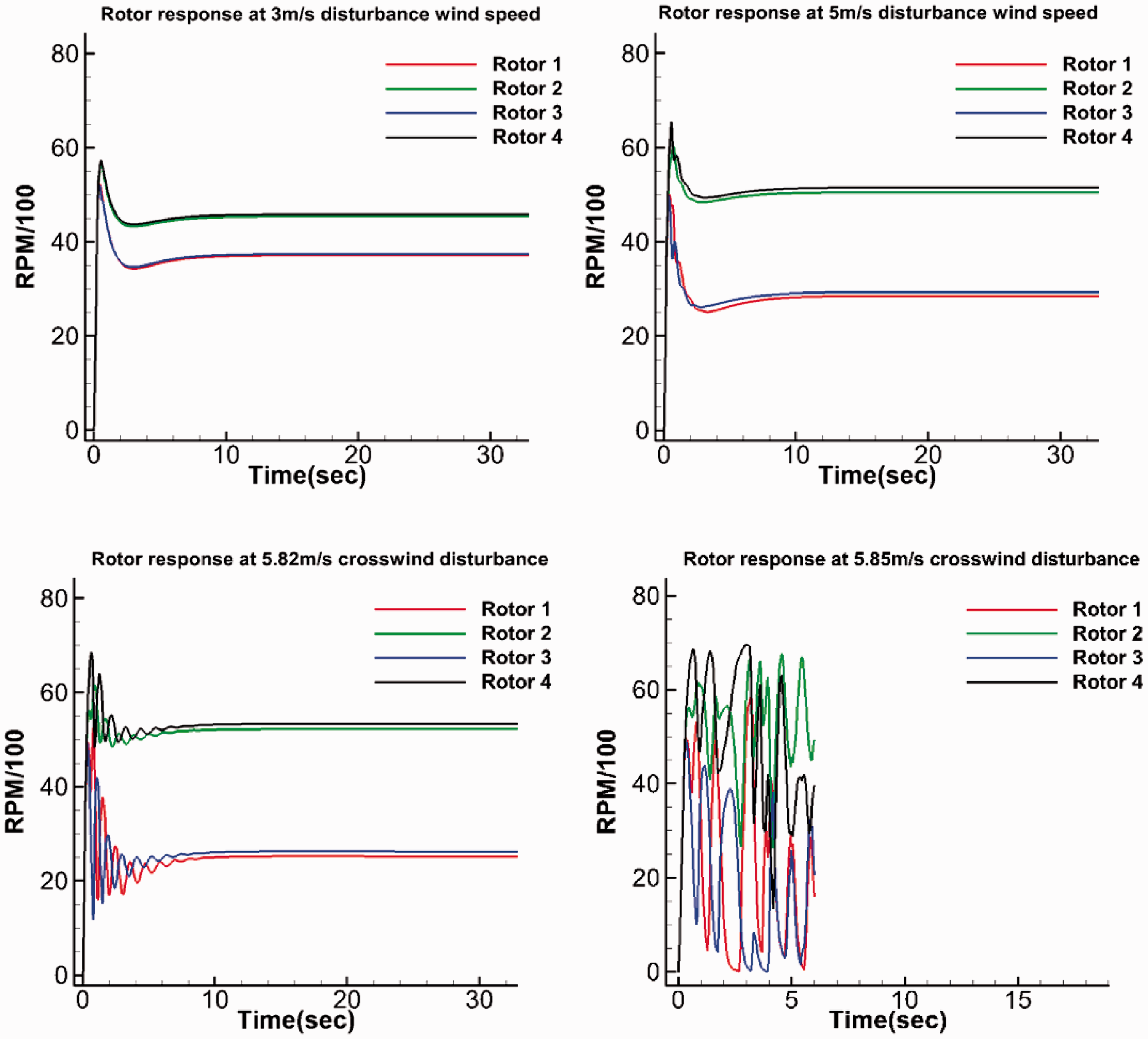
Rotation speed of each rotor at different disturbance wind speeds.
Von Karman wind disturbance
The wind disturbance is actually unsteady, varies randomly, which cannot be easily described by 1-cos wind disturbance, thus the Von Karman wind disturbance is introduced in this paper to simulate unsteady crosswind. Two variables are used to describe the Von Karman wind disturbance, the 

Disturbance wind generated by Von Karman turbulence model.

Power spectrum of the wind that subtracted the average speed.
The flight simulation of Quad-Plane against the Von Karman wind disturbance in quadrotor mode is conducted. The Quad-Plane is required to rise to 20 m height, meanwhile, the unsteady crosswind generated by the Von Karman wind disturbance model is added to the simulation system. As the crosswind is totally unsteady, the aerodynamic forces and moments act on the Quad-Plane is unsteady, which results in fluctuation of the speed of each rotor. The dynamic response of each rotor, motor current, and battery voltage during the simulation is shown in Figure 31. The voltage of the battery decreases continuously during the simulation process, which leads to the continuous decline of the performance of the motor. The simulation ends at 1238 s when the battery voltage decreases to 21.3 V and does not drop to the cut-off voltage of 21 V. At that time, the battery no longer has enough voltage to provide a sufficient dynamic response to the BLDC motor to maintain the stability of Quad-Plane.

Rotor speed, current, and battery voltage in Von Karman wind disturbance. (a) Rotor response. (b) Current consumed by motors. (c) Battery voltage.
In the light of simulation results, the dynamic electric quadrotor simulation system can be used to analyze the influence of the steady-state performance and the dynamic performance of electric quadrotor system on the wind disturbance rejection capability of Quad-Plane, which is able to help the design of the electric quadrotor system. For the target Quad-Plane, the wind disturbance rejection performance of Quad-Plane depends more on the dynamic response performance of the electric quadrotor system.
Sensitivity study
Usually, the electric quadrotor system components are selected from off-the-shelf products according to experience. And researchers of electric UAV always care about what kind of specifications is better among candidate electric quadrotor system components with similar specifications. So, what this part will do is try to find out the influence of small changes in these specifications on electric quadrotor system, and on the wind rejection performance of Quad-Plane for the better selection and design of the components of the electric quadrotor system. These parameters include the inductance
Influence of parameters on the steady-state performance of the electric quadrotor system
The influence of parameters on the steady-state performance of the electric quadrotor system is studied. Seven simulation cases are conducted by changing one parameter at a time while fixing the others, the steady-state output torque at different rotation speeds influenced by different parameters are shown in Figure 32 (where the baseline parameters come from Table 2), which show that as

Influences of parameter variation on the steady-state performance.
As
As
The motor parameters also have impacts on the matching of the BLDC motor and rotor, as shown in Figure 33. The throttle of BLDC motor corresponding to rotor working point P in Figure 33 is 80%, where the rotor speed is 5310 r/min, and the torque is 0.5

Influences of parameter variation on the matching of motor and rotor.
The current consumption of the motors with different parameters is shown in Figure 34. When
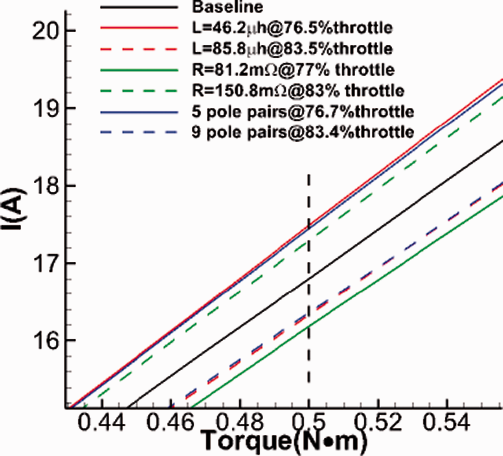
Influences of different parameters at different throttles on current consumption.
Influence of parameters on the dynamic performance of the electric quadrotor system
The parameters of the electric quadrotor system not only affect the static performance of the electric quadrotor system but also affect the dynamic performance. The evaluation of the dynamic performance of the electric quadrotor system is to observe whether the system responds fast enough to keep up with the commands given by the flight control system. If the dynamic response is faster, the Quad-Plane can reject stronger wind disturbance. To study the influence of these parameters on the dynamic performance of the electric quadrotor system, a dynamic simulation on the electric quadrotor system is conducted, in which the BLDC motor is forced to track a step signal with a rotation speed of 5000 r/min.
The influences of

Influences of electric quadrotor system parameter variation on the dynamic performance.
In order to quantitatively analyze the results, the rise time is adopted to describe the response performance of the motor, which is defined as the time that the response speed reaches 95% of the command. Table 6 shows the influence of electric quadrotor system parameter changes on rise time. The rise time of the baseline motor is 0.68 s. When the resistance increases, the rise time increases to 0.88 s, which increases by 29.4%. As the resistance decreases, the rise time decreases by 19.1%. As the pole pairs increase, the rise time increases by 11.8%, while the decrease of the pole pairs results in the decrease of the rise time by 13.2%. The decrease in inductance has minor influences on the rise time of the electric quadrotor system, which makes the rise time decreases by 7.35%.
Influences of parameter changes on rise time.

Influence of parameters on wind disturbance rejection performance of Quad-Plane
The influence of the parameters on the steady-state and dynamic performance of the electric quadrotor system is studied in previous sections, in this section the influence of these parameters on the wind disturbance rejection performance of the Quad-Plane is further studied by flight simulation. In the simulation, the Quad-Plane is commanded to rise 20 m height from the ground and hover in the crosswind disturbance environment, and the maximum crosswind speed and hovering endurance corresponding to the Quad-Plane equipped with the electric quadrotor system with different parameters are studied.
The variation in resistance, inductance, and pole pairs have influences on the wind disturbance rejection performance of the Quad-Plane. The effect of them on maximum crosswind speed that the Quad-Plane can reject, and on hovering endurance of the Quad-Plane in 4 m/s disturbance wind is shown in Table 7.
Influences of parameters on the wind disturbance rejection performance of Quad-Plane.

As the resistance increases, the dynamic response of the electric quadrotor system is slowed down, thus the maximum wind speed decreases. Meanwhile, the torque of the BLDC motor reduces at the same throttle, so the BLDC motor needs a larger throttle to generate enough torque required. Therefore, the current consumption of the BLDC motor at the same torque rises, which is manifested as a decrease in hovering endurance.
As the inductance increases, the maximum wind speed decreases. The decrease in inductance slows the dynamic response of the electric quadrotor system, thus reduces the maximum disturbance wind speed. At the same time, although the increase in inductance requires the motor to use a larger throttle to achieve the same torque, the increase in inductance reduces the current consumed by the motor at the same speed, thus the hovering endurance is extended.
Finally, the increase in pole pairs slows the dynamic response performance, thus the maximum disturbance wind speed decreases. Meanwhile, it also extends the hovering endurance.
The results are helpful to the selection and optimization of the components of the electric quadrotor system of Quad-Plane. For two electric quadrotor systems with similar macroscopic parameters such as power and speed constant, the one with lower resistance will strengthen the dynamic and steady-state performance, and the inductance should also be moderate, lower inductance will strengthen the dynamic performance but impair the hovering endurance. Meanwhile, the increase in pole pairs has an adverse impact on max crosswind speed that Quad-Plane can reject, but improve the hovering endurance.
Conclusions
In this paper, a dynamic simulation system of the electric quadrotor system integrating high-precision submodels of the electric quadrotor system components is proposed.
The surrogate-based rotor model is established to calculate the aerodynamic performance of the rotor in oblique flow. By means of CFD analysis, the thrust and torque of a 16-inch rotor in axial flow is calculated and the results are compared with the experiment results for validation. The mean error of thrust and torque between experiment results and computation results are 4.45% and 0.98%. The relationship between rotor aerodynamics, inflow speed, oblique inflow angle, and rotor speed is studied, and then the high-fidelity surrogate-based rotor model is established.
The mathematical polynomial model of BLDC motor with inductance considered is established and validated by comparing the calculation result of two BLDC motors with the test results respectively. Compared with the calculation result which inductance is not considered, when inductance is considered, the mean error of torque of the two BLDC motors between calculation result and test result decreases from 27.3% and 14.9% to 10.74% and 5.77%, and the mean error of current consumption decreases from 40.9% and 25.2% to 22.3% and 13.3%. And the power loss of the ESC is considered.
The battery discharge model is established with consideration of rate capacity effect, and is validated by means of simulating the 1.25 A and 2.5 A constant-current discharge and variable-current discharge of a 2.5 Ah battery. The simulated battery voltage of each case shows good agreement with test data and the mean error are 0.392%, 0.632%, and 0.898%, respectively. The model of the 6S-10 Ah battery which is assembled in the electric quadrotor system is established.
The integrated electric quadrotor simulation system is validated by comparing the simulation results of the dynamic current consumption of the electric quadrotor system equipped in a 5-kg Quad-Plane with flight test results. Then the dynamic response of the electric quadrotor system in 1-cos gust disturbance and Von Karman wind disturbance are simulated respectively. The Quad-Plane can reject 1-cos crosswind up to 5.82 m/s with the hovering endurance of 1288 s, while can reject Von Karman crosswind at an average speed of 5 m/s with the hovering endurance of 1238 s. The major factor that limits the wind disturbance rejection performance of the Quad-Plane is found out that comes from the dynamic performance of the electric quadrotor system.
The sensitivity study is carried out to study the influences of small changes in parameters of electric quadrotor system components on the performance of the electric quadrotor system, furthermore on the wind disturbance rejection performance of the Quad-Plane. These parameters include the inductance
Footnotes
Declaration of conflicting interests
The author(s) declared no potential conflicts of interest with respect to the research, authorship, and/or publication of this article.
Funding
The author(s) received no financial support for the research, authorship, and/or publication of this article.