
Abstract
Drones designed for racing usually feature powerful miniaturised electronics embedded in fairly light and strong geometric composite structures. The main objective of this article is to analyse the behaviour of various models of racing drones and their geometrical structures (airframes). Two approaches have been made: (i) an analysis of the information collected by a set of speed and time sensors located on an indoor race track and using a statistical technique (box and whiskers diagram) and (ii) an analysis of the know-how (flight sensations) of a group of racing pilots using a series of technical interviews on the behaviour of their drones. By contrasting these approaches, it has been possible to validate numerically the effects of varying the arm angles, as well as lengths, on a test race track and relate the geometry of these structures to racing behaviour.
Introduction
In recent years, there has been a clear increase in the use of drones for various civilian applications. This is the result of major technological and scientific advances in the control techniques of these devices. Such has been this advance that the use of drones has now become a sport with major international racing competitions taking place.
This important development in control techniques has made a considerable impact on the flight performance of these drones. However, there is little scientific literature on the design of race-quality quadrotors, and it is necessary to gather contributions on the effect of geometric structures (airframes) and their design parameters on the racing performance of these manually piloted (radio controlled) drones.
To visualise this significant lack of scientific information, the literature review starts from the first thematic milestones on vertical flight and the design of feedback control techniques applied in non-linear aircraft systems, the advantages of robust control techniques, fuzzy control logic and non-linear tracking applied to the autonomous flight of aircraft and helicopters.1–3 This review ends with innovative proposals such as navigation methods for racing drones in obstacle-dense environments based on a centre-matching method that takes information from an on-board stereo camera. 4 It can be seen how scientific development moves away from control techniques and towards other advances such as structural design, aerodynamic design and multi-objective optimisation. This has given rise to drones for high-performance sports applications.
It was found that the first and most widespread trend is the implementation of mathematically reduced and simplified dynamic models. This led to studies on the techniques and applications to control vertical take-off and landing (VTOL) using visual feedback control techniques, adaptive control, classical Proportional- Integral-Derivative (PID), and hierarchical control.5–10 The simplification of the dynamic model consists in reducing the equations of aerodynamics by a set of coefficients mostly obtained from a test bench. This bold mathematical reduction caused a dizzying rise in the development of research with drones for the monitoring, planning, and generation of autonomous trajectories,11–16 and the introduction of concepts such as agility, manoeuvrability, indoor trajectory control and drone hardware reduction. Basically, the control of the device was separated into two decoupled levels, one for the control of the drone’s movements and the other for motion planning.
The most recent studies on this trend focus on collaborative work and motion manoeuvrability.17–23 In general terms, these address the problem of controlling several drones under one general reference system (framework) tied to the body mass to be transported, with each drone having its own reference system (body frame). Consequently, interesting industrial applications and successful commercial proposals were positioned in the market.24–29 These civil applications are related to handling and transport of materials, image processing linked to precision agriculture and maintenance of electricity generating propellers among others.
Another less widespread scientific trend is the development and implementation of mathematically complex and less simplified dynamic models.12,30–40 These developments consider rotor dynamics as well as the mathematical modelling of aerodynamic forces and gyroscopic torque. Once this dynamic was understood and mastered, both in simulated and real environments, the physical effects related to aggressive manoeuvres and high-performance applications began to be considered.22,41–51 Non-linear dynamic models that take into account the thrust force and physical effects (such as the change in airflow through the rotor), control techniques, as well as measuring their effects in flight regimes other than stationary, resulted in aggressive manoeuvres and high-performance applications.
A broad perspective on the development of control techniques and their scope leads to the consideration of motor sports. In addition to the scientific publications found, a survey has been made that does not take into account the scientific method, but, extends these scopes by taking into account high performance applications.4,52–54 Although, little literature was found, the use of drones in sport and entertainment activities is increasingly the subject of systematic and rigorous studies. Moreover, it is quite remarkable that driven by the mass media55–58 and sponsored by major investors,59–62 high-performance sports applications are making inroads into social contexts and the education sector.63–65
To conclude this literature review, a specialisation in control techniques has ensured that the use of drones is safely carried out in several sectors. In addition, we are seeing the development of other traditional areas of research that are typical of aircraft geometric design and their transfer to the formal and scientific study of race drones. In other words, the overall performance, stability and manoeuvrability tasks have been guaranteed with the support of control techniques. Aerodynamic geometrical design plays a key role for achieving high dynamic performance and stability during demanding manoeuvres.66–68 In view of continuous progress in the use of drones, the potential theory of flow around arbitrary, thin and non-aerodynamic bodies is waiting to be addressed scientifically, as well as issues of flow compressibility in different flight regimes.
Finally, concepts such as speed, time, agility and geometric advantage for different trajectories and high performance should start to be approached from scientific perspectives in order to apply them to the motion of racing drones. This sports sector is truly demanding given the remarkable lack of rigorous information. This challenge will be addressed in a conservative manner by analysing experimental flight tests and practical case studies.
The present paper is organised as follows. Racing drone characteristics section provides a geometric description of drones that are designed for high-performance sports applications. The geometric restrictions of sports regulations and a table with technical data are taken into account. Since racing drone applications are always operated manually by humans, in the third section, the know-how about their flight is objectified by surveying pilots from various professional and sports leagues worldwide. To relate flight behaviour as a result of racing drone geometric characteristics, case studies in the methodology section are configured, and the procedure for carrying out the experimental flight tests is described. The racing track has been equipped with sensors to store speed and time data over flight trajectories. In general, the index data are labelled with the letter J. In analysis of results section, to identify possible relationships between the structure geometry and the behaviour of drones during flight tests, the results of the indexes are analysed using a descriptive statistical method known as the box and whisker diagram. In addition, representative cases have been chosen for each airframe model and an acceleration study has been carried out. Finally, in conclusions section, a geometric design compromise according to the most suitable racing behaviour is established.
Racing drone characteristics
Drones designed for racing are characterised by miniaturised and powerful electronics that are embedded in fairly light and strong airframes, usually made of composite materials. An airframe is the geometric structure to which the propulsion systems are attached. Specifically, the mission of the racing drone system (i.e. the combination of electronic components and geometric structure) is to travel around a racetrack or circuit at a relatively high speed while passing through different types of obstacles and trajectories. 69
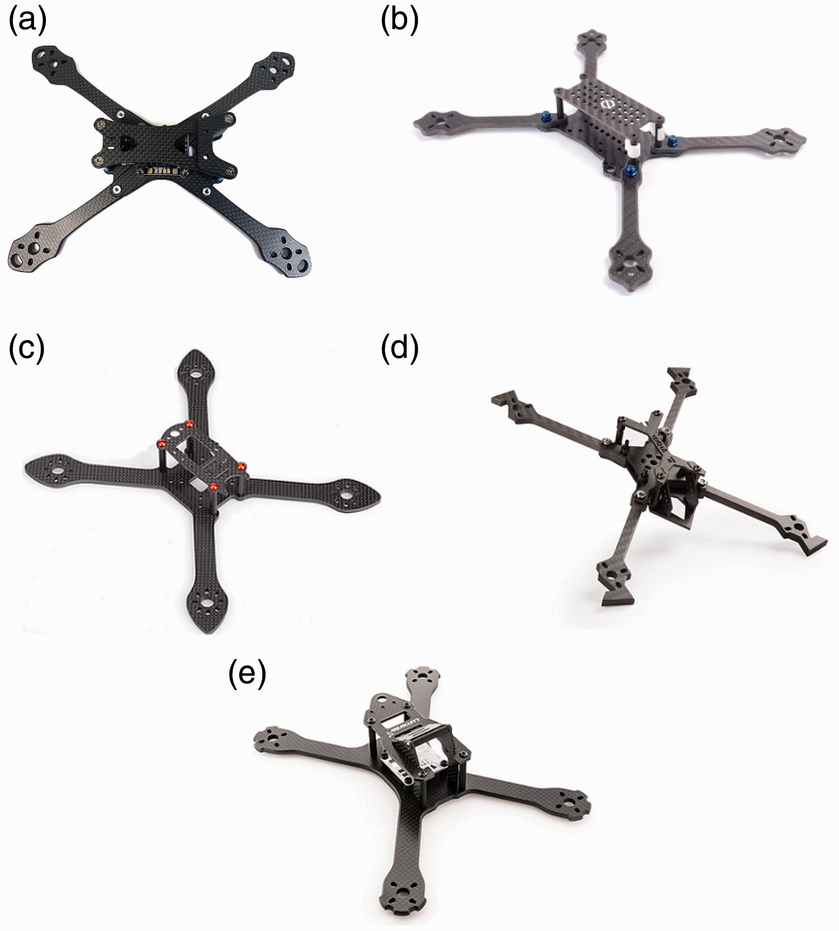
Taking into account the several aspects that define this type of drone and due to the proliferation of missions and applications70–74 in which it is possible to use a drone, interested parties have gradually made numerous contributions on how to classify drones. In those contributions, emphasis is placed on the type of wing and particularly on the number of arms needed to attach the propulsion system (motors, rotors or actuators).75–77 Weight is the main item that differentiates drone applications. A drone designed for racing applications is composed of a rotary wing with four arms and is usually designated as a micro drone. This type of drone consists of four individual rotors attached to a rigid structure (see Figure 1) and according to Mahony et al., 10 this type of structure has become a standard platform for robotics research worldwide.
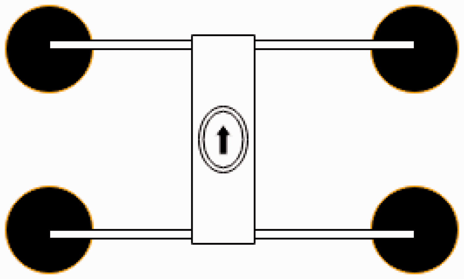
Basic airframe structure. (a) Basic geometry. (b) SY. (c) NSY. (d) HS.
However, taking into account Kumar’s premise and previous traditional and commercial classifications,78–81 a more accurate characterisation based on airframe geometry specification is needed to identify a racing drone.
Accordingly, the airframe geometric characteristics shown in Figure 2(a) are taken into account: (i) lambda
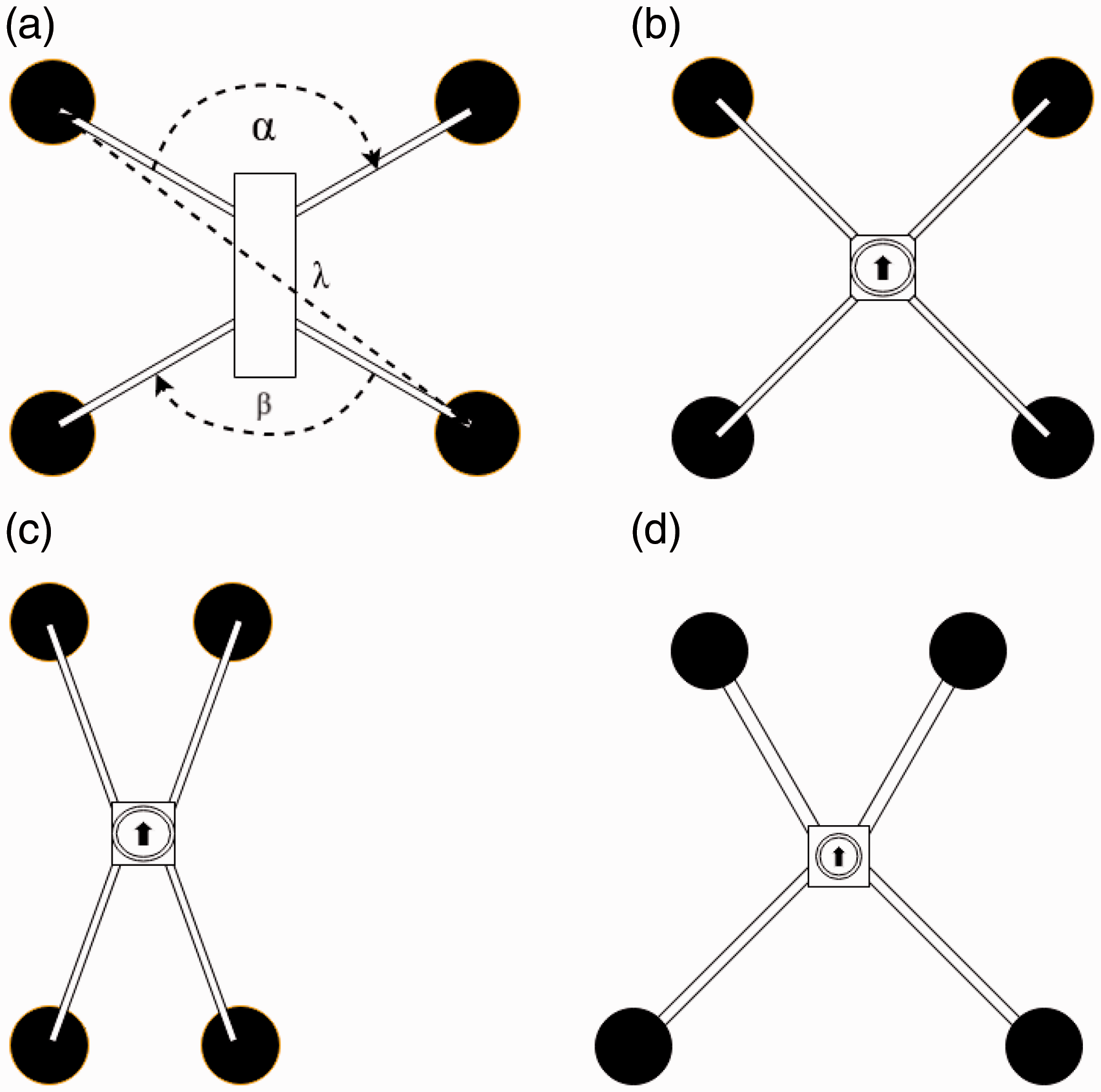
Typical racing airframe structures. (a) SY200–210. (b) SY200. (c) SY210–220 (d) SY220–230. (e) SY240.
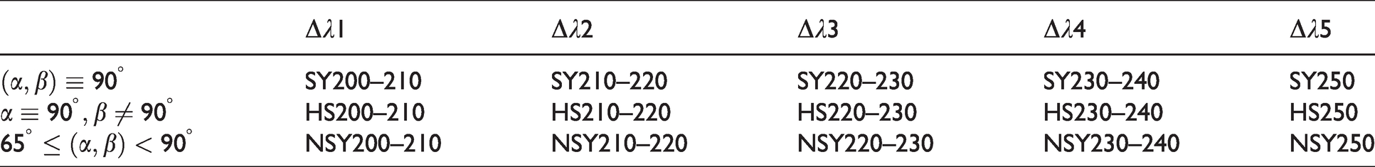
The SY structure is the set of geometrically symmetrical airframe models. As alpha (α) and beta (β) are restricted by the propeller radius, if the length of the radius varies, then SY structures give rise to NSY non-symmetrical airframe models. In consequence, hybrid shape (HS) models are a combination of angular distances of non-symmetrical and symmetrical models. Similarly, other constraints and parameters that do not affect the structural geometrical integrity of the models are shown in Table 1. A margin of error of (
Standard measure constraints.

If the above geometric definition and high-speed conditions are taken into account for short timelaps, then stability is determined by the angular distance alpha (α) and beta (β) on straight trajectories, as well as by the shape of the arms. Agility is determined by the longitudinal distance lambda (λ) for curve trajectories, by the ability to go around obstacles and by the pitch and yaw moments. Manoeuvrability is determined by the symmetry of the airframe and by the geometric relationship between the lambda distance and the angular distances
To obtain a numerical source data from alternative flight tests, some technical characteristics of the fastest racing drones have been found in Ref.82 and this information is grouped in Table 2. In addition, according to the Federation Aeronautique Internationale (FAI) and World Air Sports Federation, the speed limit in an outdoor racing circuit is
Reference technical data.

Pilot know-how
The main feature of racing drones is that they are always operated manually and are designed to be manually raced. Therefore, to measure the contribution of different airframe geometries to the overall performance of the race drone, the subjective perception of the pilot has to be considered and it must be analysed whether these perceptions are supported by objective data.
Personal interviews were conducted with a group of expert pilots from national and international professional leagues (some of the pilots are pictured in Appendix 1). The pilots were asked about the flying sensations produced by different airframes on the race track. Most of their comments related the geometry of the airframes in relation to concepts such as stability, agility, manoeuvrability, control settings and drone size.
Twenty pilots from the most representative individual competitions in the world (Drone Champion League), 83 and 31 pilots from the most representative team competition in Europe (Iberian Drone League (IDL)) 84 were included. In addition, two expert pilots from the most representative individual competitions in America (Drone Racing League) 85 and recent FAI world champions Rudi Browning (2018), Thomas Bitmatta (2019), and the female racer Arwut Milk Wannapong (2019) 86 were also interviewed. Their answers have been summarised in Table 3.
Flight sensations.

The first column refers to the total number of pilots who mentioned a particular design feature. The following columns specified how many of these pilots referred to a specific airframe model. Some of their know-how is explained below.
It was found that 63% of the pilots prefer non-symmetrical airframe structures (NSY) (see Figure 2(c)), as the angle between the front arms is smaller than the angle between the side arms. While 21% prefer a symmetrical geometric (SY) (see Figure 2(b)). A smaller percentage prefer a HS (see Figure 2(d)), meaning a structure combining symmetrical and non-symmetric geometries.
Some 36% of pilots relate stability to several geometric characteristics of the airframe. In addition, 65% of the pilots say that symmetrical structures are much more stable than the other two structures. Specifically, pilots relate stability to the airframe reaction after a control input for a straight flight trajectory or a trajectory with a turning radius. They also specify that this type of structure needs a relatively low control setting in order to navigate through any type of obstacle on the race track. Pilots such as world champion Rudi Browning (see Figure 22) say that SY structures respond equally to any input on all axes and are therefore highly stable.
Similarly, 54.4% of the pilots relate agility to the speed of response (reaction, torque) of the airframe geometry when turning or navigating around obstacles on the race track. Furthermore, 83.3% of this group perceives non-symmetric structures as the most appropriate structures for curved trajectories. Consequently, pilots such as Chang Hyeon-Kang (see Figure 19) or Mig-lon prefer NSY structures because these structures respond more quickly and achieve a more precise curve radius than the other airframes.
Some 23.6% of the pilots relate manoeuvrability and the geometric characteristics of the airframe structure to the difficulty of following curved trajectories and smoothly navigating an obstacle (accuracy) in a straight line. These pilots also see manoeuvrability as a direct consequence of the symmetry between the axes of the drone arms. In fact, 69.2% of pilots state that a symmetrical structure offers much better manoeuvrability than other types of airframes. For these reasons, pilots such as drone champion Gary Kent (see Figure 23), prefer a symmetrical airframe, that is, the pitch and roll angles are equal in magnitude and when the airframe turns on the track it responds more naturally, thereby enabling a smooth curve or a straight trajectory without much loss of height when turning.
Some 41.8% of the pilots relate the performance of the drone motion over straight trajectories to the overall size of the airframe and the space between the propeller tips. Indeed, 52.1% of pilots state that non-symmetrical structures maintain a more appropriate aspect ratio for straight trajectories. The Spanish pilot Ivan Merino (see Figure 19), and the Italian Emanuele Tomasello (see Figure 24), who participate in the IDL, agree that the space between the tips of the propellers is important. They say that small airframes should not be used when the tips of the propellers are close to each other. Instead, they prefer a non-symmetrical configuration for a typical race track and when regulations allow they try to use 6-inch airframes for the race track as larger sizes means more stable behaviour and fewer problems of turbulence.
Some 27.2% of pilots talk about the control setting and the connection with the sensitivity felt by their fingers when they move the radio control sticks. Interestingly, 46.6% say that non-symmetrical geometric structures require a greater knowledge of these settings. The young female pilot Arwut Milk Wannapong (see Figure 22) says she adjusts her speed to any type of structure, while other pilots such as YoungRok-Son (see Figure 20) say they are already accustomed to the responses of their airframe structures, and therefore changing them would be a matter of control adjustment.
Methodology
The proposed methodology consists of defining a series of mathematical indicators (cost functions) that numerically reflect the dynamic behaviour of a racing drone on the race track. This behaviour is then visually described according to the airframe model using a descriptive statistical technique known as a box and whiskers diagram. To carry out this analysis, the results of the numerical statistical descriptions are compared with the technical information provided by the pilots and which is summarised in the previous section. Based on this comparison, three airframes are highlighted as representative behavioural models for each index, and the performance of these models is then analysed. Finally, the influence of weight on the agility and acceleration behaviour of these models is considered. To conclude, a set of basic guiding rules on the dynamic behaviour of racing drones is established.
Flight test procedure
The process carried out to find similar motion dynamics that are mostly the result of the geometric configuration of each airframe is as follows. The electronic components embedded in the geometric structure are the same for each airframe (which is tested and supplied by the same airframe manufacturer to guarantee experimental homogeneity). All flight tests for the various airframe models are carried out by a single pilot. To keep the flight test configuration as clean as possible, all navigation aids provided by the flight controller BetaFlight 87 used in this study have been left at zero or deactivated. For example, aids that keep the drone flying in a straight line by avoiding altitude losses and those directly involved in the voltage signal or signal filters. In this way, the flight controller software performs the tasks related to the stabilisation of the vehicle and the pilot performs the tasks related to navigation. In other words, the proportional (P), derivative (D) and integral (I) gains that control the travel of the control lever (control sticks) or control the frequency of the motors when a voltage input for a roll, yaw or pitch turn is made, have been deactivated for the test flights (commercially known as airmode, RPM filters, dynamic filter and anti-gravity options).
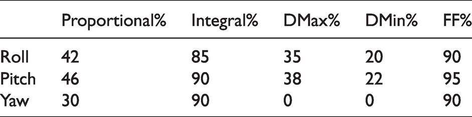
The control gains for the stability of the drone, mostly those related to the proportionality (P) or derivative (D) of the error signal, have been kept in the default values proposed by the BetaFlight software (see Table 4). This is because the developers of BetaFlight suggest that these values are acceptable for safely flying most racing drones on the market, and for all geometric structures that are in a total take-off weight range of approximately 400–500 g (a net weight of approximately 250–400 grams). In fact, the set of control gains are design in terms of robustness and not of time response performance.
PID by default.
Gains related to the integral error (I), in addition to those that control the speed of response of the control sticks, have also been kept in default values as the pilot constantly corrects such errors during the flight. If the weight of the drone is correctly placed in the centre of gravity, and the weight of the propellers is evenly distributed, these values keep the drone free of vibrations due to the rigidity of the propellers and sharp turns.
The aim is to understand the dynamic response of the drone to geometric changes by minimising the contribution of the control gains to the navigation of the vehicle. Therefore, it is possible that this dynamic response and the sensations of the test pilot are also affected by the absence of these control gains – but it should be clear that the dynamic vehicle equilibrium is not affected and a data reading that is as clean and reliable as possible is achieved.
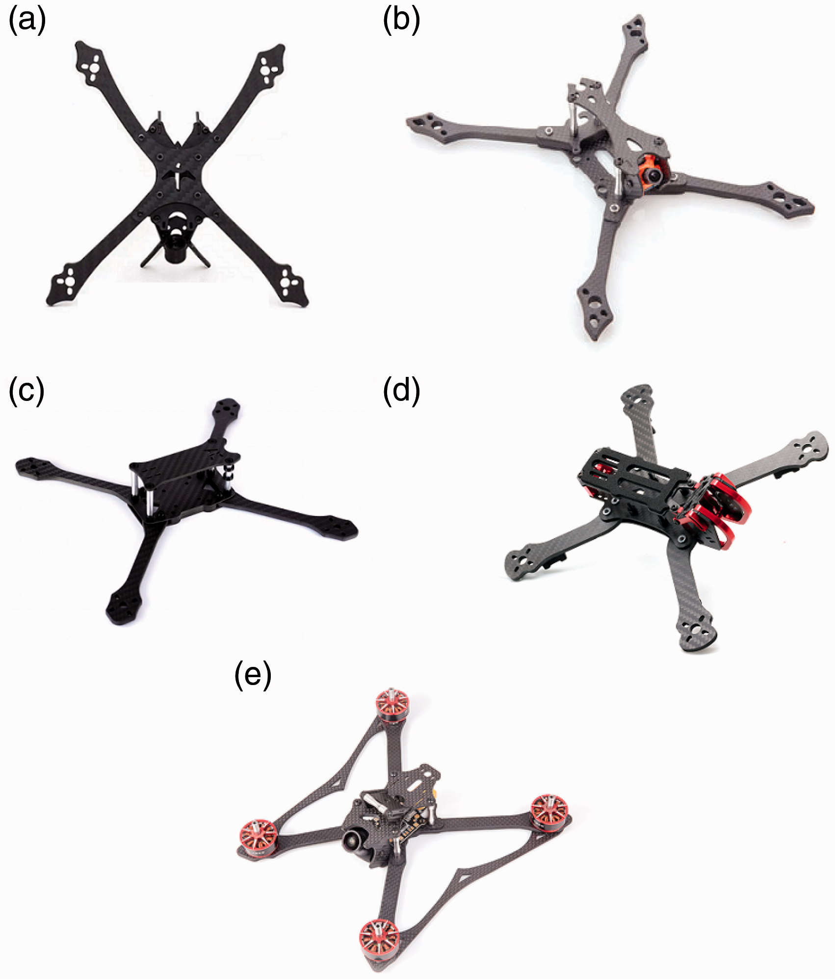
To make a robust flight test, 15 racing drones were selected in groups of five airframe models and according to the technical characteristics described in the second section. The first group of airframes corresponds to the symmetrical models (see Figure 3). The second group corresponds to the hybrid models (see Figure 4). The third group corresponds to the hybrid models (see Figure 5).

Symmetrical airframe models SY. (a) HS200. (b) HS210–220. (c) HS200–210. (d) HS240. (e) HS220–230.
Hybrid airframe models HS. (a) NSY230–250. (b) NSY200. (c) NSY200–210. (d) NSY210–220. (e) NSY220–230.
NSY.
The geometric specifications of the airframe models can be found in Table 5. In the table heading there are five lambda lengths between 200 and 250 mm (
Geometry of the airframe models/case studies.
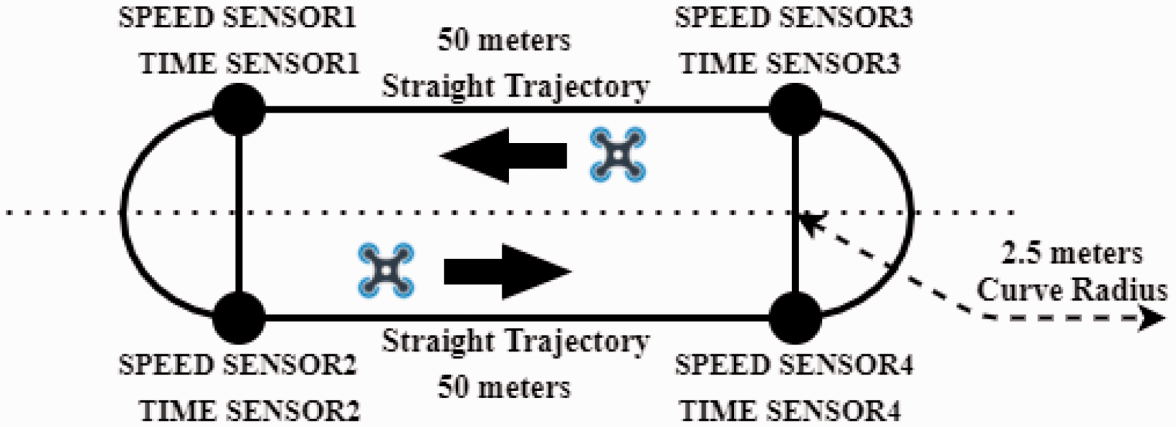
All flight tests were made in an indoor race track and so GPS signals are not available, in consequence, the 3D position vector is not calculated by the flight controller BetaFlight. Also, no optical tracking system was available due to the dimensions of the race track. For those reasons, there is no real-time data about the 3D position and trajectory for the drones. However, a system of sensors that measure time and speed was appropriately distributed around the race track to capture basic information (see Figure 6).
Race track for the flight tests.
A test flight consists of four laps of the race track with each selected model. The sensors located around the race track record the speed and lap times (see Figure 6). This procedure is performed ten times for a total of 40 laps.
The race track used for the flight test had two 50-m straight lines joined at the ends by two semicircles with a radius 2.5 m. The circles represent the time sensors and operate with universal video radio frequency sensing technology,88,89 the lines also represent the speed sensors which are Doppler effect sensors positioned along the entire trajectory. 90 To observer some of the flight tests being carried out click on the following link reference. 91
Recorded flight data has been organised in three indexes as follows. The letter J1 stores the velocity magnitude for straight trajectories. J2 stores the speed for curved trajectories. Finally, J3 stores the time for curved trajectories. Consequently, the indexes are directly related to the behaviour of each chosen airframe model and highlight the situation of the race on straight and curved trajectories.
Analysis of results
If the aim of the race is to achieve the fastest speeds and shortest lap times on straight trajectories and curves, then the best, worst and intermediate results of the numerical data obtained will be highlighted. To this end, the representativeness of the data will be the differentiating feature between each set of airframe models and this will be visible in the box and whiskers diagram.
The median lines of symmetry establish the stability or reliability of the index results, while the dispersion of the data indicates the variability of the index. Therefore, the flight data highlighted are characterised by minimal variability and slight asymmetry. To establish the basic rules of dynamic performance, the results representative of the highlighted behaviour are compared with the technical information provided by the pilots.
Table 6 summarises the characteristics of the race circuit and flight tests, while Table 7 provides the electronic components and airframe models chosen for flight tests and subsequent analysis.
Characteristics of flight tests.

Electronic components of the models.

Straight trajectories index J1
Pilots state that the symmetrical airframe models SY are highly manoeuvrable on straight flight trajectories. Despite these statements, the pilots prefer the NSY non-symmetrical airframe models. As manoeuvrability is related to reaching the fastest speeds as often as possible, the speeds recorded by the Doppler sensors were located on a straight line of 50 m and the flight test results have been grouped and plotted in Figure 7. Initially 15 airframe models were tested (see Figure 5), then the data from the representative models were analysed and compared with the information given by the pilots. In this way, the contributions of the geometric structures (SY, NSY and HS) to the racing behaviour were defined.

Behaviour index J1.
Initially, the dispersion of the speed data obtained by the hybrid airframe model HS(240) is clearly noticeable, making it an unreliable model for analysis. It is remarkable that the HS(200–210), the NSY(210–220) and NSY(220–230) models stand out for achieving the highest and lowest median speeds. However, their data distributions are also widely dispersed and asymmetric, consequently, this behaviour is unrepresentative and unreliable.
The SY(210–220) (see Figure 3(c)) and the NSY(200) (see Figure 5(b)) models develop the most consistent results and stand out with a representative high-speed median indicator. In contrast, the SY(200) model stands out with the slowest representative indication, while the HS(210–220) and HS(220–230) models achieve an intermediate representative speed performance. The HS(210–220) model (see Figure 4(b)) produces the most representative result. This means that these models reach the most reliable speed behaviour for straight trajectories and are suitable for analysis.
Preliminary, the representative models with lambda lengths (wheelbase) less than 220 mm and wet areas (overall size) between 156 and 141 mm2 are the initial geometric characteristics best suited to straight trajectories, regardless of the angular distances between their arms. The SY models have a larger wet area size (length by width) and a higher weight (81.7 g) than the other airframes, and yet the frequency of their speeds is the most constant of all those observed. The NSY models with angular distances between 65° and 90° (
In addition, the HS models in the range of 65° and 90° for both angular distances between their arms, i.e. (
Specifically, Figure 8 shows the data taken from sensors 4 and 1 (see Figure 6). It shows the time taken by the representatives models to travel the straight lines of the track. The NSY(200) (see Figure 5(b)) and HS(210–220) (see Figure 4(b)) achieve similar straight line times, and these are considerably faster than the times achieved by the SY(210–220) model (see Figure 3(c)). Their average times are between 0 and 1.33 s, while SY(210–220) average times are between 0 and 1.47 s, which means a distance or gap per time interval of 0.14 s, and so the first goal of the competition to obtain the fastest race time is achieved. Consequently, the NSY and HS models would be the most suitable for these trajectories.

Straight time performance.
Figure 9 shows the readings of sensors 4 and 1 (see Figure 6), and this reflects the top speed reached by the representatives models at the end of the straight trajectories.

Straight speed performance.
The speed performances are quite similar, achieving rates of up to 71 and 126
Figure 10 represents the average acceleration produced by the change in the magnitude (modulus) of the velocity vector (1) of the representative models. Furthermore, it is the relationship between the data from sensors 2 and 4, and sensors 1 and 3 (see Figure 6).


Straight acceleration performance.
It can be observed that the peaks of the accelerations of the NSY(200) have a remarkable tendency to fall, while the accelerations of the NSY(210–220) suffer an important fall in the early time intervals and after the time 6 interval do not reach the accelerations of the other two models in any instant of time. In other words, the speeds between the different time intervals indicate that the SY(210–220) changes speed more quickly than the other two models. Moreover, since the NSY(200) and HS(210–220) do not manage to convert the gap they obtain per time interval into a race advantage, this indicates that the SY(210–220) achieves better straight flight trajectories and this validates the contribution of the representative airframe.
It is evident that the speeds achieved by all the airframe models are quite similar, as usual in high-performance sports competitions. Furthermore, the differences between the time frequencies are a reading of the straight trajectories. The non-symmetric models achieve the quickest times, which means covering the same distance in trajectories suitable for a straight line. In fact, the high dispersion of these data also reflects a great diversity of flight trajectories, as well as the possible lateral deviations and loss of height or excessive tilt angles. Undoubtedly, the distances travelled by the symmetric models are longer, but their accelerations are quicker on the chosen trajectory, which means they achieve the fastest speeds at the end of the straight line. In other words, symmetrical models are highly manoeuvrable.
Accordingly, the numerical index J1 shows a high degree of similarity with the situation expressed by the pilots. So the configuration design of the symmetrical structures with lambda distances (wheelbases) of between 200 and 220 mm, angular distances between arms of 90°, and an average net weight of 300 grams (without battery and payload) produce a better racing behaviour for straight trajectories due to their high manoeuvrability. While a hybrid geometry with alpha distances of 65° and beta distances of 90°, and an average net weight of 280 g represent an intermediate design option. Finally, the non-symmetrical geometries demand a high level of expertise in control settings to become highly manoeuvrable models and really take advantage of their geometric design. This model needs the support that has been minimised in the control settings to achieve a higher pitching moment (due to the shorter lambda lengths on that axis and thus optimising performance on straight trajectories).
Index J2 curve trajectory
The pilots state that the NSY models are more agile during the curve trajectories than any other type of airframe, and for this reason, it is the most chosen geometric structure. If this agility is related to reaching the highest curve speeds as often as possible, then, to visualise this behaviour, the Doppler speed sensors were located on a 2.5 m radius curve and the data obtained from 15 different geometric structures (see Figure 5) was grouped and plotted in Figure 11. Initially, representative models were chosen so that flight test data and pilot statements could be compared.

Behaviour index J2.
The NSY(200) and SY(200) airframe models stand out for having the slowest average curve speed, and clearly they fail to develop a regular and reliable behaviour due to the wide distribution of their speeds. In fact, most are concentrated in the first quarter of the box. As a result the median line of the numerical data is not representative for validating the curve behaviour of such models. In addition, the HS(200–210) shows the most widely dispersed curve speed index.
The numerical data obtained are highly reliable for the NSY(200–210) (see Figure 5(c)) and quite reliable for the SY(220–230) (see Figure 3(d)). Specifically, the speed data distribution for the NSY(200–210) is highly compact between the quartiles; furthermore, this model develops consistently high speeds over the curve trajectories. However, the graphs also show that repeatability is not highly constant, but remains remarkably good. Similarly, the data flight of the NSY(210–220) and SY(240) shows the worst speed behaviour among the airframes. While the HS(200), HS(210–220), NSY(220–230), NSY(240) and SY(200–210) models achieve intermediate curve performances between the best and the worst results.
The SY(210–220) and SY(220–230) stand out, initially, for reaching the highest median speeds in the curve; however, the distribution of their data is notably dispersed towards the quartiles below the median line and towards the points of lower magnitudes. Consequently, behaviour at these speeds is quite representative, but not close to that of the NSY(200–210) described previously.
If the race goal is to achieve the lowest speeds and constant behaviour during the curve, then the numerical data described by the SY(240) and NSY(210–220) models are initially the most reliable. Therefore, the data behaviour of the HS(210–220) and HS(240) is reliable and located in an intermediate curve speed zone. However, the HS(200) (see Figure 4(a)) stands out considerably from these two previous models, and is therefore a representative model between the curve performance of the SY and NSY airframes.
In principle, lambda (wheelbase) distances of no more than 210 mm with angular distances of the NSY models offer a considerable speed advantage on curved trajectories. However, the symmetry of the SY models with lambda distances no greater than 230 mm offers a constant frequency of speeds, but without reaching the highest speeds.
To analyse in detail the previous speed behaviour look at Figure 12. The numerical difference (subtraction) between the magnitudes of the speeds recorded by sensors (3–4) and sensors (1–2) shows that the NSY models are considerably slower on the curves than the other two models. However, a constant speed rate is achieved in the first intervals of time. The HS models achieve the fastest speeds and manage to sustain a more constant frequency of speeds than the SY models, contributing on average a difference of 25

Speed curve performance.
The geometric configuration with angular distances of 65° for alpha and 90° for beta, together with lambda distances of 200 mm, and an average weight of 270 g, seem to better fit these trajectories. In addition, the aspect ratio resulting from the geometric relation of angular distances in the range of 65° and 90° (
It is not possible to attribute to the aspect ratio of the NSY models the competitive advantage that the pilots express about curved trajectories (a higher roll moment over the curved trajectories due to a longer lambda), because the SY models have a higher aspect ratio and sometimes reach speeds highly similar to those of the NSY. Similarly, although the SY models show a consistent behaviour at lower speeds, this behaviour does not guarantee adequate performance over the curved trajectories and cannot be considered a reliable and real-life racing situation.
To validate the above perspectives, it is necessary to relate the speed with the lap times achieved in order to better understand the characteristics of this curve behaviour as a function of the airframe geometry. Moreover, by combining these two numerical data it is possible to justify the preference for a certain type of airframe. In this way, the index J3 is analysed below.
Curve time index J3
Agility is related to reaching the fastest curve speeds for a curve radius of 2.5 m as often as possible. Taking into consideration the speed results of the J2 index, the time index data obtained from the video radio frequency sensor during the flight tests for curved trajectories for the airframe models has been pooled and graphed (see Figure 13).

Behaviour Index J3.
Initially, the NSY(200) and SY(200–210) reveal the worst results of all the airframes, and clearly achieve the slowest curve time index (J3). The NSY(200) now achieves the fastest curve speed index (J2), while the SY(200–210) reaches intermediate speed zones. The index distribution is quite disperse for the NSY(200), meaning that its time curve behaviour is not constant, while it is highly symmetrical for the SY(200–210). Consequently, the SY(200–210) could be a representative solution for a good behaviour for curve trajectories speeds, unlike the NSY(200).
Four of the five NSY models have their median lines above 0.55 s, and the NSY(200–210), NSY(210–220), and NSY(240) models are placed in the upper zones of the time index (J3). Furthermore, they are placed in the fast, slow, and intermediate curve speed zones (J2) respectively. Similar times during curved trajectories at different speeds mean that the range of angular distances offers good manoeuvrability. However, the distribution of their speed data is highly dispersed, revealing an unstable and inconstant behaviour, and so their flight trajectories are not suitable. But also it should be clear that the most important characteristic of their curve performance is that regardless of the speeds achieved, the curve times are highly significant when compared to the times produced by other airframes. This means that the contributions made to the performance of these models in the curves by the control gains that have been minimised are being compensated by the geometric characteristics of the airframe.
Four of the five SY models have their median lines under 0.55 s, and the models SY(200), SY(210–220) and SY(240) are placed in the upper and medium zone of the time index results respectively. Furthermore, the SY(200) and SY(210–220) models are placed in the high performance speed zones, while SY(240) is placed in the slow speed zone. Notice that speed index (J2) and curve index (J3) show that their data are less dispersed than the data of NSY models (meaning that the data shows a more stable, constant, and similar curve behaviour than the other models). The most important point to note is that the SY models, given their geometric characteristics of symmetry, are easily able to repeat their behaviour and this makes them more effective than the NSY models as the duration of the flight test is extended.
Finally, the HS(200), HS(200–210), HS(220–230), and HS(240) airframe group is placed in the slow zones of the time index. In fact, the median lines of the curve time are above the 0.5 s line. The HS(200–210) shows a compact distribution and also a highly dispersed index for the curve speed. Hence, its trajectories are similar at different speeds, but do not reach the highest speeds, and consequently, it is not a constant racing behaviour. The HS(240) shows fairly similar midzone time and speeds (i.e. similar curve trajectories) due to the highly compact data. It is important to note that, the time index of the curve for the HS(200) is very dispersed and it is in the middle zone of all the sets and speeds are similar. Therefore, the speed performance is faster than that of the NSY models, but slower than that of the SY.
The difference (numerical subtraction) between the magnitudes of the times recorded by sensors (3–4) and sensors (2–1) (see Figure 6) of the representative models SY(240) (see Figure 3(e)), HS(200), (see Figure 4(a)) and NSY(200–210) models (see Figure 5(c)), shows that the NSY model has longer curve times than the SY model (see Figure 14), meaning that during 7 out of 10 trajectories, the SY achieves a considerably faster time than the NSY, taking into account that the NSY reaches the fastest curve speeds. In other words, the NSY fails to take advantage of its geometric design and does not manage to convert its maximum curve speeds into a race advantage. Manual control becomes more complex at high speeds.

Curve performance.
The SY airframe models mostly show the best overall behaviour during curved trajectories. Different lambda lengths in the range of 200 and 250 mm
Significantly, the SY models do not reach speeds produced by the NSY for curved trajectories, but in contrast, they perform quicker times at slower speeds, which is interesting because this means they hold better trajectories. Certainly, it is possible to find a particularly favourable performance for a non-symmetrical configuration case-by-case according to the lambda length. However, this favourable performance should be accompanied by additional control aids, such as, for example, shortening the travel of the control sticks to achieve a greater turning moment with respect to the roll axis to improve the performance provided by the original geometric structure.
The airframe models preferred by the pilots are chosen assuming the race goal of making curved trajectories more agile, as well as navigating the obstacles of the race circuit quickly and precisely. Therefore, the non-symmetrical airframes with angular distances in the range of 65° and 90° (
Consequently, the preference for choosing NSY airframes is not due to the contributions made by the specific geometry of the airframe, but rather to the contributions made by the control settings. This explains why many pilots choose this structure.
Airframe weight and agility
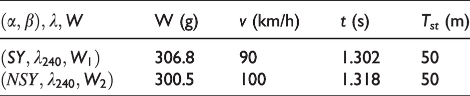
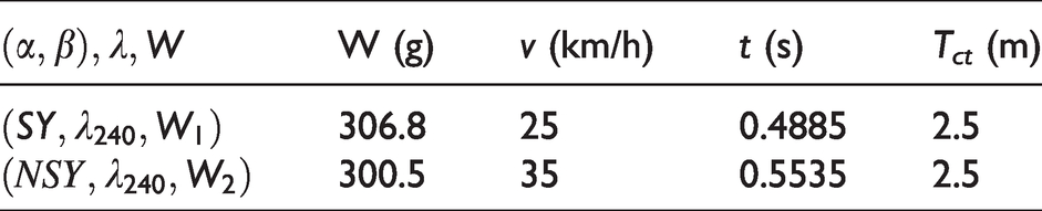
The pilots also explain that agility is highly compromised by the structural weight of the airframe models and the different configurations for angular alpha and beta distances (α, β). Hence, the NSY and HS models must have their basic geometric configuration and weight altered to find a better performance in any of the trajectories. Accordingly, two models with the same lambda distance (λ), but different angular distances, were chosen (see Tables 8 and 9) to validate this point.
Straight trajectory performance.
Curve trajectory performance.
Straight trajectory performance.
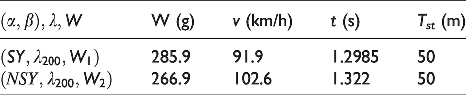
Firstly, note that weight difference (2) affects speed performances (3) and lap time (4) on straight trajectories (Tst). It is important to realise that the SY model achieves a better lap time 


Notably, the NSY model reaches the fastest speeds due to its light weight; however, the penalty is quite evident on curved trajectories. These trajectories are wider with respect to the axis of rotation, uneven, and not smooth. Therefore, top speed gain does not convert into a time gain.


The apparent advantage for curved trajectories offered by the geometric modification of the NSY models is insufficient to counteract the characteristics of the curve, and so an advanced knowledge of control adjustment and drone turning moments (roll, pitch, and yaw) is necessary. Racing drones move forward with an angle of inclination (pitch angle) that is usually greater than 45 degrees to achieve high forward speeds. Consequently, if this is not understood, then the speed gain is unavoidable and the design advantage offered by the NSY geometric condition is lost.
The pilots emphasised the influence of airflow with respect to the separation between the tips of the propellers for straight trajectories as this directly affects size and the wet air area. For this reason, two airframe models with different angular distances alpha and beta (α, β) and a minimum lambda distance (λ) were numerically analysed (see Table
The SY models, despite being the heaviest airframe structures (see Table 11), clearly take advantage of the speed and lap time in comparison with other types of airframe models on straight and curved trajectories. Firstly, speed change for the SY model is quicker than for the NSY and HS models, and consequently, they achieve the fastest lap times. However, reaching faster speeds is no guarantee of achieving better lap times on straight trajectories, hence, lap time behaviour depends on the trajectories chosen.
Secondly, adequate separation between the tips of the propellers avoids an area of over-energised airflow. In fact, this separation is mainly a function of the angular distances alpha (α) and beta (β). Furthermore, angular distance (β) for the NSY models on the longitudinal axis is shorter than the distance on the lateral axis, and so the propeller tips are further apart from each other. The proximity between the tip of the propellers for the SY models is symmetrically similar for all axes. Indeed, airflow will remain in the same proportion regardless of the alpha and beta angles
It is important to realise that trajectories without motion and speed behaviour correction are not directly affected by the reduction of lambda distances (λ), but they are affected by gap separation, and possibly by the aerodynamic effects on straight trajectories. Stability and manoeuvrability are mainly functions of the alpha (α) and beta (β) angular distances on straight trajectories. Consequently, a suitable wet area and overall size characteristics of the airframe models of about 156 and 170 mm are needed, i.e. a range of lambda distances (λ) between 220 and 240 mm with angular distances of exactly 90° (
Acceleration performance of the NSY(200–210 model)
The acceleration performance of the NSY(200–210) representative model (see Figure 5(c)) is shown in Figure 15. The data are taken from the accelerometers in the flight controller embedded in the airframe, and so it represents the change in speed of the drone in coordinated space with respect to the race track. The vertical axis of the three graphs shows the magnitudes of the acceleration on the pitch, roll, and yaw axes; while the axial axis shows the time per four laps on the race track (see Figure 6).

Acceleration on pitch, roll and yaw axis.
The axial length between the vertical dotted lines that cross the whole graph represents the accelerations during the straight and curved trajectories, ST and CT respectively. In general, note that the pitch axis acceleration tends to increase towards negative values during straight trajectories. These negative values are because the drone is flying horizontally with a tilt angle (pitch angle) that is usually between 45° and 80° and is continuously supported by this acceleration.
The graph of roll acceleration more clearly shows the airframe behaviour during curved trajectories. Since a racing drone advances horizontally at a fixed pitch angle, it faces the trajectories of the curve with rotations on its roll axis, while a conventional drone changes direction by rotating on its yaw axis. Negative and positive values indicate changes in direction of 180°.
The graph of yaw accelerations is a relative measure of the power of the four motors and their thrust force. That is, their magnitudes are in the positive zones because the drone is constantly moving. During a straight trajectory, this acceleration tends to be equalised, seeking balance with the other two accelerations to constantly maintain maximum speed and flight altitude (height). During curved trajectories, this acceleration tends to increase and this is mainly due to the change of direction of the speed vector and not its magnitude.
Not losing height during turns means increasing yaw acceleration until reaching the roll acceleration magnitude produced by the change of direction, while pitch acceleration magnitude remains constant. This means that if pitch acceleration decreases, or yaw acceleration does not reach the roll acceleration values during the curve trajectories, there is an increase or loss in altitude, respectively.
An ideal trajectory is given by keeping the speed change constant during the pitch moment (zero acceleration) so that the racing drone remains fixed at its pitch angle without falling to the ground or gaining altitude. To achieve a change of speed on the straight trajectories it is possible to increase the pitch angle of the airframe (no more than 90°) by increasing the yaw and roll moments to maintain current height. However, this would imply reducing the field of vision and in the most extreme cases looking at the ground while the airframe advances horizontally. Flying forward in this way, it would be sufficient to increase the roll moment while keeping the yaw and pitch accelerations constant to achieve an effective change of direction during curved trajectories.
If the racing drone is flying forward with the maximum possible pitch angle, then the drag force increases since a larger portion of the upper airframe area (upper plate) impacts with the air, i.e. the wet air zone and the skin friction increases. In addition, the effects of the lift force are minimised until the weight of the vehicle is balanced.
For the case of the representative model, note that the accelerations on the pitch angle range from negative magnitudes to peaks of approximately minus 39
For curved trajectories, this model decreases the acceleration by reducing the pitch angle. At the same time, the acceleration on the yaw axis increases slightly and the acceleration on the roll angle increases much more so – up to about
On straight trajectories and after the turns of a curve, the accelerations over the yaw and pitch angles increase again considerably (a second peak of
Finally, the representative airframe models have equivalent geometrical characteristics, and flying them requires a precise acceleration regime for each geometry. Consequently, not achieving these flight regimes creates an advantage for symmetric models because balancing their accelerations is mostly equitable and intuitive.
Conclusions
An exhaustive review of the literature has been carried out and a lack of scientific literature on the design of race-quality quadrotors has been found. To address this gap, the contribution of geometric characteristics to the dynamic behaviour of racing drones is analysed by comparing data from experimental test flights with the know-how of racing pilots. Results show that the SY symmetrical airframe provides a constant time frequency and speed rate during trajectories because its flight behaviour is reliable and this means high levels of manoeuvrability and agility. The behaviour of non-symmetrical NSY airframe models is also highly suitable for racing, but performance is strongly linked to a good understanding of the dynamics of acceleration and moments of pitch and roll angles (especially during straight trajectories), and therefore, the non-symmetrical NSY airframe does not succeed in transforming its geometric characteristics into a performance advantage. Finally, the dynamic behaviour of SY models is very similar to the sensations expressed by the pilots. However, most pilots prefer non-symmetrical models because of the dynamic advantage of a higher roll moment (due to the model’s elongated arms during curved trajectories). However, this preference is not justified by this geometrical characteristic, but by a correct understanding and a fairly precise adjustment of the control aids.
Footnotes
Declaration of conflicting interests
The author(s) declared no potential conflicts of interest with respect to the research, authorship, and/or publication of this article.
Funding
The author(s) disclosed receipt of the following financial support for the research, authorship, and/or publication of this article: This work was partially supported by project RTI2018-096904-B-I00 from the Spanish Ministry of Economy, and by project AICO/2019/055 from Generalitat Valenciana.
Appendix 1
Airframe model (SY) – Data indices I.
Tests
Airframe structure (mm)
(SY)(200)
(SY)(200–210)
Empty weight (g)
73
81.7
Gross weight (g)
285.94
295.68
J1 (km/h)
91.9
94.9
J2 (km/h)
35.1
40.5
J3 (S)
0.5302
0.4847