
Abstract
In this work, we present a novel design for vertical surface contact using a two degree of freedom robotic arm attached to a Micro Air Vehicle. To achieve this, we propose a controller based on a Gain-Scheduled Proportional–Integral–Derivative approach. In previous works, the Gain-Scheduled Proportional–Integral–Derivative method was used to control the attitude of the Micro Air Vehicle, thus mitigating the perturbations induced by the movement of the arm. The novel approach of this work focuses on the achievement of an automatized full-contact with a rigid vertical surface using a Micro Air Vehicle with a robotic arm. We have improved the capabilities of the Gain-Scheduled Proportional–Integral–Derivative control to consider the inherent issues of approximating to a flat structure in order to carry out an aerial interaction task successfully. For the Micro Air Vehicle’s position feedback, a motion capture system is used in this work. A paintbrush attached to the end effector of the arm is used to draw over a whiteboard surface to show the full contact of the aerial manipulator. A distance sensor is added to the on-board sensors to measure the distance between the vertical surface and the system to ensure a correct distance and achieve a safe contact. Experimental testing results show that the controller can maintain a stable flight with sufficient accuracy to complete the aerial interaction tasks.
Keywords
Introduction
Research on aerial manipulation using unmanned Aerial Vehicles (UAVs) or drones has grown in recent years due to potential applications of this useful system in different fields.1,2 Aerial manipulation is achieved by means of having a drone with a robotic arm attached to it. In contrast to drones with a suspended load, in aerial manipulation, the robotic arm can be controlled either manually or autonomously. A gripper could also be part of the arm, placed at the end of the arm, enabling tasks such as grasping.3–5
If a drone can grasp objects and carry them from one place to the other, then their capabilities extend beyond video recording, the typical application to date. However, the arm movements may introduce perturbations that have to be compensated for the flight to remain stable.6,7 Even when only contact between the aerial vehicle and a structure in the environment occurs, the dynamics of the system may dramatically change, compromising the stability of the flight.
Some relevant implementations for the active interaction with environment use of UAVs are presented in Delamare et al., 8 Eren et al., 9 Jimenez-Cano et al.,10,11 Liang et al., 12 and Nguyen et al. 13 The dynamic properties of UAVs with attached-lower-side manipulators are similar to a pendulum, which causes disturbance on each task developed. For instance, in Delamare et al., 8 an UAV system is designed to hook itself to some anchor points on the ceiling. The presented study is promising, but the reported result is restricted only in a simulation environment; also, the problem of bringing near a drone to a ceiling is different from a vertical wall. In another interaction task, a bridge inspection operated by an UAV with a robotic arm is proposed in Jimenez-Cano et al. 11 In the latter, the authors use a Proportional–Integral–Derivative (PID) controller in real-time for an UAV with an attached tool. However, the PID controller can handle neither the variations in the model nor the change in the operating conditions. 14 The research in Jimenez-Cano et al. 10 presents a similar case for the application of UAVs in bridge inspection. In the paper, a comparative study is carried out for a designed backstepping algorithm with integral action and a PID for a quadrotor equipped with a robotic manipulator. The results show the superiority of the backstepping algorithm based on a decoupled approach, but interaction disturbances are not studied in detail.
The flight of aerial vehicles in indoor scenarios is a challenging effort especially in tight spaces, most research on UAV control has concentrated on handling dynamics when operating in free spaces, where aerodynamic interactions with nearby surfaces can be neglected.15–17 Although aerodynamic effects are mentioned in some works, most of them treat these interactions as small disturbances, in which the stability control must compensate using feedback.8,14,18 One of the most mentioned aerodynamic actions is the wall effect, which is a disturbance caused by the air of the rotors bounced in the wall. For full contact with a surface, wall contact must be considered in the stability control.
The expectation of the capabilities of UAVs has increased to another level, wherein the flying system interacts with its environment in a set of uninterrupted contact tasks, in a general perspective, researchers are interested in the use of UAVs in an active physical interaction mission. To achieve the interaction task, it is necessary to take into account new issues which can be divided into three main disturbance-problems that compromise the flight of the system: The arm movement, The wall effect, and The full contact. We consider that each one of these three stability issues must be taken into account in the control design to reduce the disturbance and ensure the stability in flight mode. We describe these three types of disturbances below.
Arm movement
A significant problem arising in aerial manipulation is related to the dynamic behavior of the vehicle changing due to modifications of aerial mass distribution and dynamics by grasping and manipulating objects. The main effects appearing and making a different dynamic behavior of the UAV with an attached-manipulator are the following:
Displacement of the center of mass from the vertical axis of the vehicle. (A typical aerial vehicle considers a fixed center of mass in the main control.) Variation of mass distribution: the moments of inertia change significantly in the arm moving. The dynamic reaction forces and torques generated by the movement of the arm. (All these forces are seen as disturbance for UAV.)
These effects are not considered in a typical aerial control, so the attached arm seriously compromises the flight stability.
The wall effect
When the UAV in flight mode is close to a wall (vertical rigid structure), a disturbance force induced by the propellers of the rotors affects the stability of the system (see Figure 1). Such disturbance increases when the distance between the UAV and the surface is smaller. The length of the arm is limited to avoid an exaggerated displacement of the center of the mass; this coerces the system to approach to the wall more than the required distance to reduce the called wall effect, producing a disturbance that must be considered in the control design.

Wall effect. Disturbance induced by an aerial system near to a vertical rigid structure.
Full contact
The contact with the surface generates a rejection force affecting flight stability (see Figure 2). The value of this rejection force depends on the contact force exerted by the arm. In a typical fixed arm design, the links transmit the rejection force from the end effector to the base of the arm. In the aerial manipulator design, the arm base is attached to the vehicle, applying the rejection force as a disturbance to the UAV directly. The goal is to simplify the interaction control keeping the contact force of the arm at a minimum value. We conducted experimental tests to obtain both the wall-effect and the contact rejection force.

Here is shown a full contact of the end effector of the robotic arm with the rigid vertical surface. The force of the arm produces a contact force on the surface.
Thus, it is clear that aerial manipulation has a potential of applications but also it involves several challenges to be addressed. In particular, these challenges have not been totally addressed for Micro Air Vehicles (MAVs). In this sense, we take into account the MAV changing behavior due to the movement of the arm proposing an experimental study to determine the variation in the plant dynamics. We use the outcome of this study to establish a set of controllers that enables the MAV to follow a desired trajectory.
In this work, we employ a new manipulator arm of two degrees of freedom (DoF) especially developed for a commercial MAV, a quadcopter of the company Parrot, model bebop 2.0. We also propose to incorporate a Gain-Scheduled (GS) approach to the conventional PID controller to ensure the stability of the proposed aerial manipulator. We determined the gain values of a set of PID controllers experimentally; this represents a novel technique dealing with the drawbacks of perturbations in the aerial manipulation systems.
We should highlight that this work has been built upon our previous work. In Luna et al., 19 we presented for the first time the design of our proposed aerial manipulator, a robotic arm with two DoF, attached to the bebop 2.0. We also introduced a controller to compensate for the perturbations generated when deploying the arm during hovering flight; the controller added constant term, which was learned experimentally by observing the position of the arm and the direction in which the drone moves (due to the perturbation) with a motion capture system. In Luna et al., 20 we proposed to use a PID controller with gains defined according to the GS scheme, we compared this strategy against the previous learning-based controller and found that the GS reduces the reference error in our aerial system during hovering flight. In Luna et al., 21 we presented, for the first time, experiments where the MAV autonomously approaches a vertical surface and makes contact with the robotic arm, which is deployed once the MAV is close to the surface within a certain distance. To demonstrate the effectiveness of the control strategy, based on GS PID, the MAV attempts to draw a horizontal line on the surface (white board). This is an automatized routine where a reference point is given for the MAV to approach the board, make contact and fly to the side, following a line. At the end of the robotic arm, a pen was placed to draw the line.
Therefore, the work presented in this paper is the consolidation of the works mentioned before. In particular, we have enhanced the GS-PID controller to increase the stability of the system during the contact stage. We also added a distance sensor to the on-board hardware for the MAV to measure its distance w.r.t to the vertical surface to control the forward motion toward the surface, thus avoiding excessive contact pressure. This enabled the MAV to draw a square shape on the surface.
In order to present our work, this paper has been organized as follows: section “Related work” discusses the state of the art related to the topic of aerial manipulation; section “Hardware design and configuration” describes the hardware of our proposed aerial manipulation systems; section “Control strategy” describes our proposed control strategy to achieve control of the vehicle during the aerial interaction; section “Experimental framework and results” presents our experimental framework; and finally section “Conclusions” discusses our conclusions and future work.
Related work
The number of projects which consider an UAV system with a manipulator has considerably and suddenly increased in recent years.22–26 However, these initial works on aerial manipulation focused on the stability of the system in controlled scenarios where the main issue is the weight, and the disturbance induced by the manipulator.
By providing one of the first works in physical aerial manipulation, the use of UAVs in Baizid et al., 27 Bazylev et al., 1 and Bellicoso et al. 2 with a manipulator incorporated in the system was implemented to study the stability behavior in flight mode. In Jimenez-Cano et al., 10 an aerial manipulator for a contact mission is presented. The system consists of an arm of three DoF attached to the upper structure of the UAV to inspect the base of high structures like a bridge. An aerial manipulator for transportation missions is presented in Liang et al., 12 the control architecture of this work consider the estimation of the mass of the transported object to stabilize the system during pick up phase. The mentioned works report promising results in aerial manipulation. Unfortunately, these studies focus on the problem of coupling the manipulator on the flying system, and the mass distribution, but the wall effect, and the full contact disturbance are not discussed in these implementations. In Delamare et al., 8 the discussion of the interaction forces of an aerial manipulator and the disturbances induced by the surrounding objects is presented with simulation results. One of the initial implementations in which the arm disturbance and the contact are considered are presented in Kocer et al.14,28 In Kocer et al., 14 the performance degraded by the contact phase and external forces are considered for interaction with the ceiling. In these implementations, the discussion of the wall effect is not presented.
In Lin et al., 29 the research for an aerial interaction mission in an outdoor scenario is presented. The commercial UAV matrice 100 was considered for the implementation in this work to grasp an object from the ground successfully. The Hexa rotor UAV was considered in Zhang et al. 30 to design an aerial manipulator capable of grasping and object with strong wind disturbance. A robust Hexa rotor was also incorporated in the aerial manipulation system to bear the hardware components added to detect and grasping objects. Although previous works obtained considerable results experimentally, they do not consider forces like wall effect due to the size of the vehicles. The size of the systems is a fundamental value to consider in the control model for aerial interaction. Full constant contact is not reported with big-size drones.9,12 Big-size UAV presents flight robustness that can be helpful in the stability control. Nevertheless, this type of drones represents potential costly damage for the vehicle and the work environment in case of a system failure.31,32
In this work, we propose the use of a small-size drone to prevent this situation and the consideration of the wall effect in the control design. However, the robustness of MAV’s and actual controls are not sufficient to ensure stability in interaction tasks. In Jimenez-Cano et al. 10 and Khatoon et al., 33 the pure PID and/or Linear-Quadratic-Regulator (LQR) approaches are implemented to control the stability of aerial manipulators. Unfortunately, the conventional PID approach is not sufficient to achieve stability in interaction task and the system might end up with a crash as a result of an inappropriate reaction during the mission. For this reason, we propose a Gain Scheduling PID (GS-PID) control technique to maintain stability in interaction tasks, improving the manipulation significantly. Being different from conventional PID, GS-PID can adjust the gains depending on the phase of interaction; this property of GS-PID approach is useful in this challenging application.
The following issues are noted in the current studies: (i) most of the works consider just one or two of the critical disturbances in the interaction task; (ii) most of the applications consider big-size vehicles due to the robustness; and (iii) the wall effect is not considered in most of the proposed controls.
Hardware design and configuration
The aerial manipulation system designed for this work consists of a MAV, which is the commercial drone bebop-2 with a two DoF arm attached in the lower part of the structure. The vehicle is capable of loading an extra weight of 400 g, adequate to bear a low-weight robotic arm. The design and the incorporation of the entire system are described below.
The MAV arm design
For manipulation and interaction tasks, robotic arms can provide the necessary DoF to achieve the objective.22,23 In contact with surrounding objects, for example, an n-DoF arm could supply the stiffness and versatility to the vehicle accomplishing the goal involving contact with the environment. The n-DoF arm could also provide a safe distance between the aerial system and the object for interaction.
The design of the robotic arm proposed for the aerial manipulator shown in Figure 3 was developed thinking in two main aspects: first, the interaction mission. The task consists of exerting a force on a rigid surface, drawing a figure without losing contact to the surface. For this objective, the robotic arm must be adapted to the necessary movements to contact the surface successfully and also providing adequate distance between the vehicle and the surface. This action reduces the disturbances induced by the proximity of the rigid structure from the rotors of the aerial vehicle. Second, the proposed design must maintain a relationship with the dimension and the physical capabilities of the system to guarantee the ideal performance in flight mode. Even with these considerations, robotic arm behavior can alter the flight efficiency of the vehicle reducing the accuracy of the interaction. For this reason, a control strategy considering the robotic arm perturbations must be implemented to achieve the proposed task.

Design of a two-DoF arm. The weight, dimensions, and shape were estimated considering for the commercial MAV bebop-2.
The length L1 and L2 of the extended arm (see Figure 4) designed for this work provides an adequate distance between the surface and the aerial system to maintain a safe flight preventing a collision of propellers with the surface. Nevertheless, the distance is not wide enough to reduce the wall effect considerably, for that reason, the wall effect disturbance must be considered in the control algorithm. Two actuators were also attached on each link to provide the movements θ1 and θ2 of the arm. The arm structure is light enough to allow the aerial system to take off suitably and keep a stable flight; however, the inadequate stiffness of the arm must be considered in the control design, preventing the exceed force supported by the arm.

The angles θ1 and θ2 represents the movements of links 1 and 2.
A set of pieces was designed to prove the satisfactory performance of the interaction control, allowing the arm to hold a pencil and mitigate the friction and contact forces. Figure 5 shows the proposed end-effector for the experimental task—the design of the end-effector permit reducing the interaction area to three simple points. Thus reduces at the same time the friction in the contact phase. The end effector also rotates, adjusting the angle to the slope of the no total vertical surfaces. In addition to the structure, some components were incorporated, providing movement, communication, and power to the arm. Figure 6 shows the actuators, sensors, and control board completing the MAV robotic arm designed for the task proposed in this work.

Free movement of the end effector to adjust to a semi-vertical wall.

Components of the robotic arm. An Arduino Nano board to control to servo motors attached to links 1 and 2 of the arm. The Bluetooth module provides wireless communication with ground station. The Ultrasonic sensor measures the distance between the system and the wall. A lipo battery energizes all components.
Complete system
The structure of commercial drone bebop-2 is not designed to carry a robotic arm below. We developed a set of extension legs to allow the vehicle to take-off and landing safety. Since the bebop-2 uses a sensor at the base to measure the ground distance, the robotic arm was attached in the structure carefully to avoid any obstruction for the sensor. Figure 7 shows the complete system developed for this work. The robotic arm (see Figure 8) does not interfere with the sensor of the drone even when it is deployed due to its design. The distance sensor (ultrasonic sensor) is located at the robotic arm base, just below the front of the structure preventing the obstruction with any part of the arm, the legs, or the vehicle.

Full system. The two-DoF arm attached in the lower part of the MAV bebop-2. Four extension legs were incorporated to the vehicle to allow take-off and landing.

Deployed arm. The length of the arm provides safety distance between the vehicle and the wall.
When the arm is deployed (as in Figure 8), the distribution of the center of mass is overcharge to the front of the vehicle, causing a physical displacement in the system from its original position; nonetheless, the stable flight is not compromised. The displacement is studied in experimental tests to include it in the control strategy.
The sensor location also provides a distance measure between the vehicle and the surface. When the arm is extended, the distance of the vehicle to the end effector is 15 cm. This value is called the “safe distance” (SD), and it is the minimum distance permitted for the vehicle to close the surface, preventing an accident (see Figure 9). In the control algorithm, SD indicates that the system is in the contact rank, and the system must maintain the position in the x-axis achieving the interaction task. In the following section, the control algorithm is detailed.

Here is shown the safe distance between the vehicle and the structure.

Vehicle Interaction scheme.
Control strategy
In this section, we describe the GS-PID control technique for the attitude of the aerial manipulator developed to tackle the disturbance problem and to achieve the proposed interaction task. The goal is to output an action command for the MAV to rectify the position of the system altered by the disturbance forces described before. Thus, the control algorithm is presented in the next sections.
PID control
Taking into account that the dynamical model of the MAV is an under-actuated, highly coupled, and nonlinear system, a number of control techniques have been developed for such class of similar systems.34,35 Among them, sliding mode control, which has drawn much attention for researchers, has been a useful and efficient control strategy for handling systems with significant non-linearities, uncertainties, time-varying properties, and bounded external disturbances. Most of the control strategies have been proposed to preserve an appropriate behavior in the stability of the MAV on finite-time.
A PID algorithm used in autonomous systems continuously calculates an error value e(t) as the difference between the reference position and the actual measured position and applies a correction based on proportional, integral, and derivative terms (denoted as P, I, and D, respectively). The PID algorithm is described as follows

In equation (1), let kp, kI, kD be the gains of the PID control. The control signal is denoted by u(t) and e(t) is the control error. The proportional, integral, and derivative sections can be interpreted as control actions based on the past, the present, and the future of the system. The gains of the PID controller can be designed based on the features of the system, providing they can be achieved or estimated precisely. We mentioned some related works regarding PID strategies for aerial manipulation. In 2010, Pual E. I. Pounds 36 presented a dynamic model of an aerial manipulation system for object capture by combining a simple planar model of a helicopter UAV in hover under PID control with a suspended bogie linkage representation of a compliant gripper. Matko Orsarg et al. 37 developed a P controller for the speed loop and a PI controller for the position loop, taking into account the dynamics of the system composed by a MAV with a two DoF robotic arm. A PID controller is designed for the (x,y) position and yaw orientation of the MAV.
Gain scheduling method
To compensate for the disturbances of the robotic arm, we have incorporated the Gain-Scheduling technique within the PID control to enhance the flight performance when a robotic arm is attached to the vehicle. The gain-scheduling method uses measurable variables correlated with changes in a process dynamic to define controller parameters. The gain schedule technique is an approach to the control of nonlinear systems that uses a set of linear controllers to provide adequate control at various points of system operation. To tune the controller, one or more variables (called variables to be programmed or adjustment variables) are used.
Once the variables have been selected, the regulator parameters are calculated for several operation points based on a given control strategy. In this work, for GS-PID controller, a set of pre-tuned gains are applied to the controllers. No rule specifies the number of zones or points of operation in which the range of operation of the plant should be divided. In this sense, it is the choice of the designer.18,38,39 The following steps were established to implement the GS-PID controller: first, auxiliary variables were chosen. If these variables can be monitored, then it is possible to change the parameters of the controller if the dynamic of the system/process changes. For this work, the variables chosen were the angles of the links of the robotic arm (θ1, θ2). Second, after the auxiliary variables were chosen, the operation points Pn are determined. These operation points are the position Pe in (X, Y, Z) of the end effector of the arm, which depends on the values of θ1 and θ2. Finally, the parameters of the controller are calculated for a certain number of working conditions, depending on the adjustment variables. Thus the controller is adjusted for each operating condition. The calculated parameters are the gains Kp, KI, and KD of the PID control, which now depends on the values of θ1 and θ2. The equation (1) with the gain-scheduling method can be rewritten as follows:

Distance measurement
The measurement of the distance between the vehicle and the surface is essential for the control to achieve full contact and to guarantee a safe flight. For this reason, a distance sensor (see Figure 6) was incorporated into the system to obtain this crucial parameter. The sensor uses sound to measure the distance of an object in front of the sensor. The following equation is used to obtain the distance

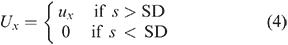
The distance value is incorporated into the controller to improve the performance while also preventing the vehicle from crashing on the wall. The signal control ux is limited when the distance s is inferior to the safe distance SD. The following equation represents the new signal Ux. In the following section, the complete control system is described
Proposed control scheme
The GS-PID control developed for this research uses the actual position of the system to ensure the stability in a desired point or trajectory. Obtaining reliable information on the position is imperative to guarantee the satisfactory performance of the control. The VICON camera system (see Figure 11) is used to obtain a precise value of the attitude parameters of the aerial manipulator. The sampling frequency of the cameras is 100 Hz. The VICON system data shown in Figure 11 represents the position of the measured object in the workspace; this information is used to feedback the GS-PID control.

Virtual environment of VICON system. The VICON cameras supply translation and rotation information of an object in the workspace. The translation a rotation values of X, Y and Z in the purple box represents the position of the blue point in the VICON space.
To obtain the gain values for the different operating points, we studied the behavior of the system when the arm was deployed during hovering. First, we chose 10 positions for the arm, then, in flight mode, we sent the arm to each position, and we captured the displacement of the vehicle due to the disturbance as in Figure 12. The displacement is the difference between the final position and the initial position. According to this displacement, we estimate the command value necessary to return the vehicle to the initial position. Finally, we tune the gains to increase the response of the system in each operating point. The command value is a data composed of four dimensionless values called

Measurement of the displacement of the system due to the movement of the arm.
The VICON system is used to capture the displacement of the vehicle, as shown in Figure 13. The VICON system uses an origin point to determine the position of an object in the workspace. We use this information to calculate the displacement. As is shown in Figure 13, the must significant displacement is in the x-axis.

Displacement of the vehicle due to the movement of the arm captured by the VICON system.
Once the stability of the system with the arm movement is achieved, the next step is to study the wall effect in the vehicle in order to mitigate it. The perturbations on the MAV derived from the wall effect increase when the distance between the vehicle and the wall decrease. We considered three different distances as operating points, as shown in Figure 14. When the vehicle is in a distance of 25 cm or more from the wall, the system is in distance A. When the vehicle is in a distance <25 cm, the system is in the distance B. When the system is at 15 cm from the wall, the arm is in distance C and is touching the structure, at this point, the arm has been deployed at its maximum length, which defines the minimum distance the MAV can approach the wall.

Wall effect disturbance calculated for different distances.
Similar to our approach to compensate for the disturbances induced when deploying the arm, we define gains for the operating points by analyzing the performance of the system in the three cases defined by the distance between the MAV and the vertical surface (A, B, C). This enables us to tune the gains aiming to achieve a stable contact of the wall.
The depiction of the interaction control in the block diagram of this work is shown in Figure 15. The different positions of the robotic arm and the wall effect produce different disturbances, which can be calculated using the error as a reference to the displacement of the system; this instability is represented as noise in the block diagram affecting the position of the vehicle directly. The error is the difference between desired position (DP) and real position (RP) of the system,
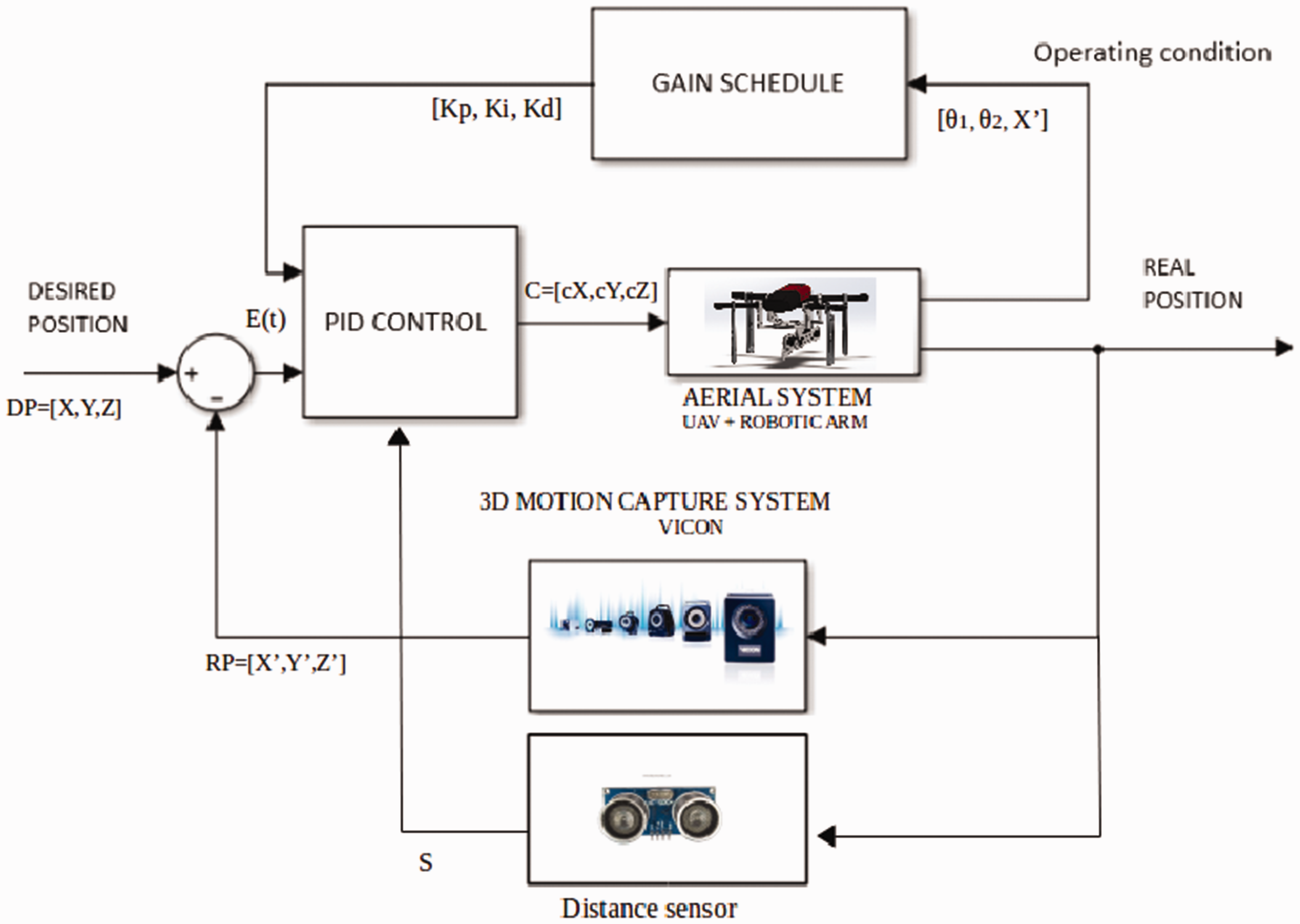
Block diagram of the system. The adjustment for position of the aerial manipulator is provided by the gain scheduling and PID control blocks. VICON and distance sensor blocks provide the feedback to the system.
The PID control box in the block diagrams contain the four controllers (see Figure 16) designed to control the attitude of the system. To control orientation, we use a standard PID controller as in a previous work. 20 The most important controller is the PID X control due to the disturbance is higher in comparison to the Y and Z axis. The gains of the orientation PID control are fixed; meanwhile, the gains of the PID x, PID Y, and PID controller depends on the operating point.

GS-PID controllers for the attitude of the system. A standard PID controller is used to control the orientation.
Experimental framework and results
The proposed control strategy was evaluated via experimental tests in an indoor environment. The manipulator incorporated to bebop-2 is composed of two links with a dimension of 10 cm (L), 0.3 cm (W), and 4 cm (H), each one with 0.12 kg (m). A Bluetooth module provided communication with the control to manipulate the links of the arm. The Robot Operating system (ROS) is a collection of software frameworks for robot software development, which allows a full connection between all connected devices with the central control. Figure 17 shows the different types of communications for the drone, the arm, and the VICON system with a central computer, in this computer, the calculations of the GS-PID control are made and sent to the aerial vehicle. ROS can be programmed by Python language, and the system allows multiple codes to run simultaneously. ROS also provides a communication package for VICON and bebop-2. The different communication codes for every sub-system can subscribe and publish information in the main code. The control in the main code receives information from the VICON and distance sensor and sends commands to the bebop-2 and the arm.

Communication scheme. ROS provides a full interaction between different systems. The commands of the interaction control are sent to the vehicle by wifi, the information of position are sent by ethernet connection, and finally, the robotic arm is controlled by Bluetooth.
The aerial manipulator in stationary mode maintains the robotic arm contracted to allow the system to take off. Once the system is in flight, the arm can be deployed to the maximum extension. In Figure 18, the deployment of the arm is presented. The movement described in the figure produces disturbance, which affects the attitudes of the vehicle. In the previous work, 20 the stability problem was considered using the GS-PID strategy. Figure 18(f) shows the final pose of the arm; this provides 15 cm of the distance between the surface and the propellers of the drone assuring a safe performance of the system.

Extended arm. The movement of the arm was designed to produce a low disturbance. (a) Initial pose and (f) final pose. A video with the experiments and results is available in the following link: https://youtu.be/ZDL6DdMxsj0
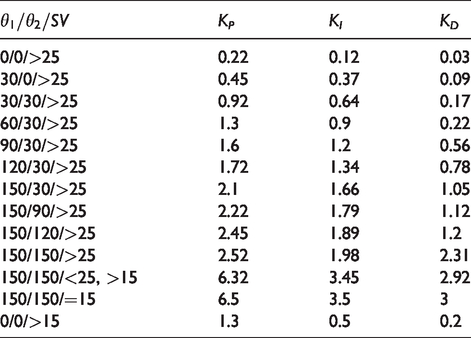
According to the movements described on the last figure, a set of operating points were selected for the GS-PID control. The gains Kp, KI, and KD of each operating point were obtained in a series of experimental tests, the complete explanation of the operating point method can be consulted in Luna et al. 20 Table 1 shows the value of the gains of the selected operating points.
Set of gains for the operating points.
Automated aerial interaction
Before trying to draw a figure (full contact) with the aerial manipulator over a whiteboard, it is necessary to demonstrate the stability flight even with disturbance of the arm and the wall effect. Each disturbance impedes the end effector to contact the surface adequately. Once the stability of the aerial vehicle with a two DoF arm is insured, the interaction task can be tackled. Figure 19 shows the results with a set of gains obtained experimentally in the first tests (red line). A Kp gain was defined for every control ui, and then

The system maintains a stable flight during arm movement in proximity to a wall (purple line). The system maintains a better stable flight during arm movement in proximity to a wall (green line).
The first developed GS-PID control accomplished the goal of stability near to the wall; however, it was not stable enough to guarantee full contact. The stability of the system was improved experimentally until the error between the position of the vehicle and the DP was close to zero. GS-PID control with final gains allows a stable flight better than the first tests. When the stability of the system close to the surface was proved, next step was to study the behavior of the system in full contact with the surface. The GS-PID control was modified to move the end effector over the whiteboard, drawing a line. If we considered the initial pose of the system as

Sequence of movements to draw a line over the white board.
The line drawn by the system is shown in Figure 21, even when the line is not perfectly straight, it was drawn continuously proving a full constant contact which is a significant result for the aerial interaction problem.
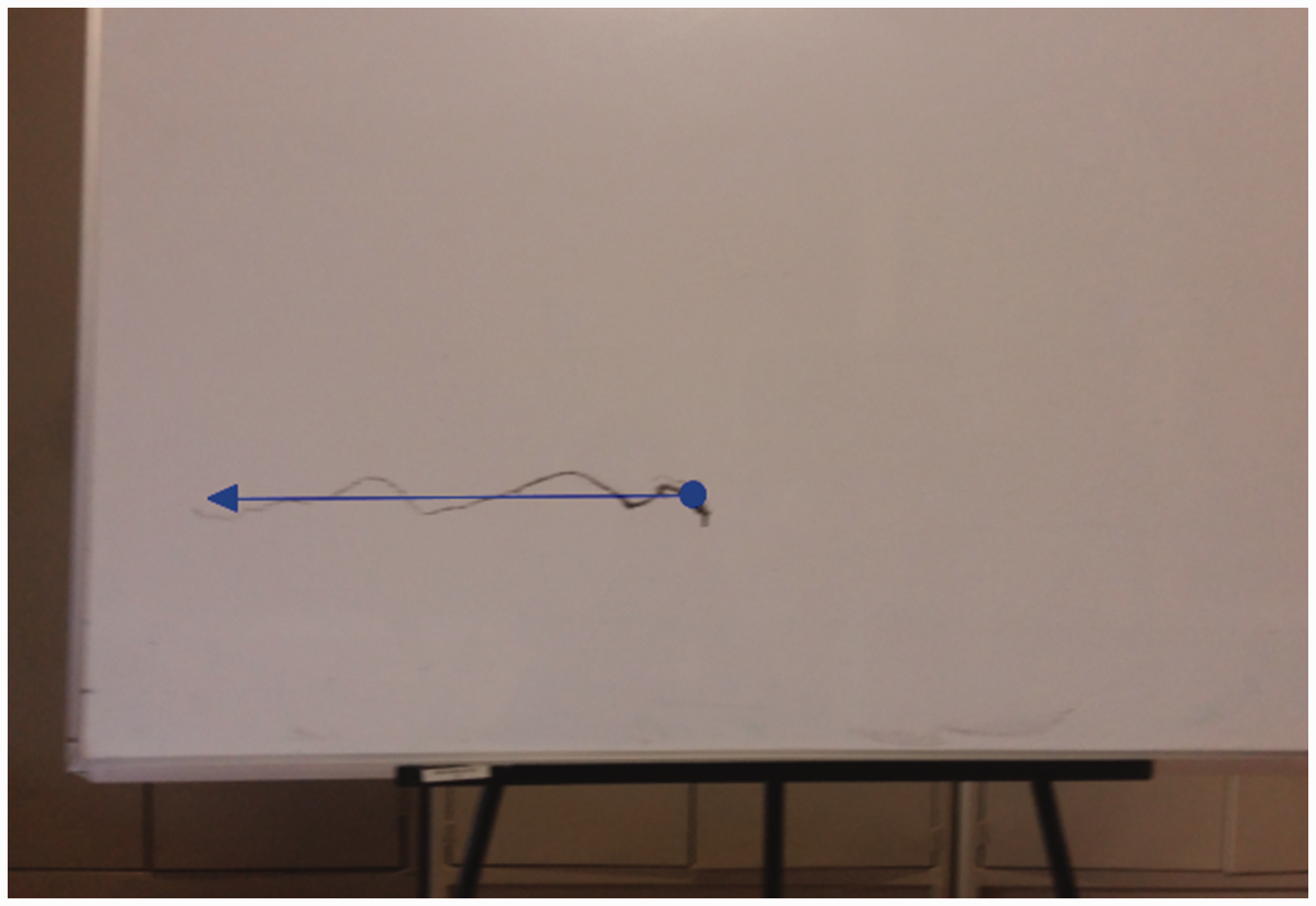
First result of interaction control. The black line was drawn by the aerial manipulator, and the blue arrow shows the direction of the movement.
Figure 22 shows first results in the experimental phase (purple line). In comparison with results using gains of Table 1 (green line), an improvement of behavior of system is appreciated, and graphics show the constant contact of the system which maintains the position in the x-axis (same distance to the surface) and z-axis (altitude), while the vehicle moves in the y-axis (displacement to the left).
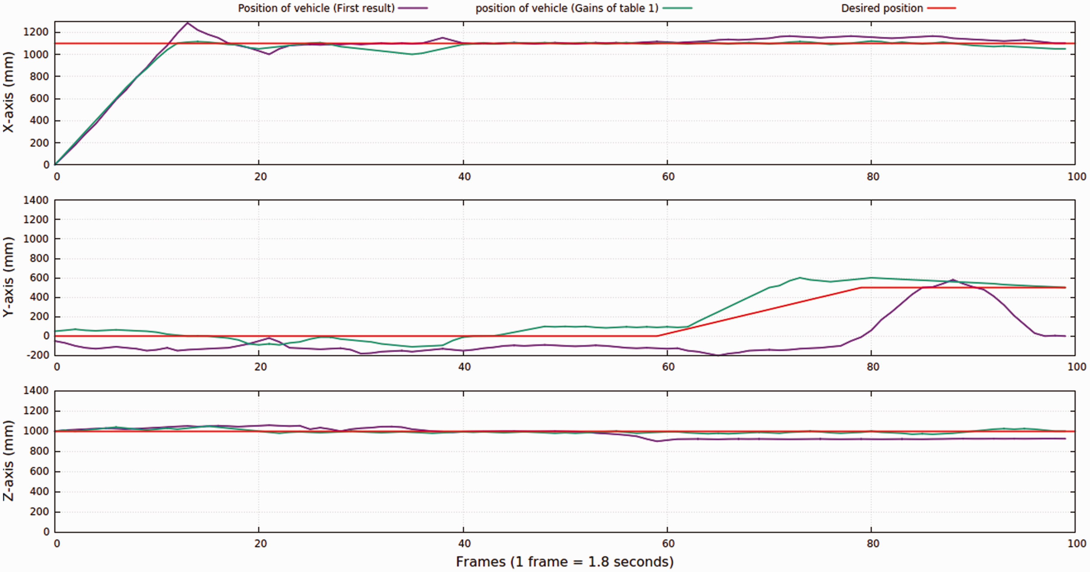
Interaction control results. The system maintains a stable flight during arm movement in proximity to a wall (purple line). The aerial manipulator maintains a stable flight and attempts to follow the reference (green line).
In the final step, we prove the effectiveness of the control designed by drawing a figure (in this case, a square) in the whiteboard, increasing the performance of the previous result (see Figure 21). As in the last experiment, the control first ensures contact of the end effector with the surface (Figure 23(a)) then begins the displacements left-up-right-down to finish the square (Figure 23(d)). Once again, the initial pose is (0, 0, 1), the vehicle moves to the second pose (0, 0.13, 1), then pass to the third pose (0, 0.13, 1.3), the fourth pose is (0, 0, 1.3), and finally the systems returns to the initial pose (0, 0, 1).
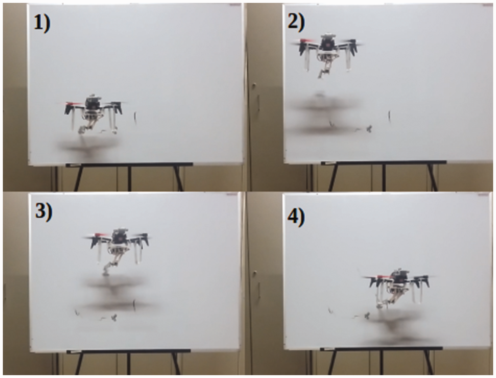
Sequence of movements to draw a square over the white board.
Figure 24 presents the sequence carried out by the system to achieve the task of drawing a picture, as in the last result, the line is constant, proving a full contact in all the sequence. Due to added weight, the system presents oscillation in the z-axis.

Second result of interaction control. The black line was drawn by the aerial manipulator. The blue arrows show the direction of the movements.
Figure 25 shows the results of the interaction task but with sensor off (purple line). The control tries to maintain the contact distance, but it fails most of the time. Also in Figure 25, the results of interaction task but with sensor on is shown (green line). The tracing of the reference in the x-axis, y-axis, and z-axis is obtained by the sensor and the GS-PID control developed in this research and represents a new result in the Aerial Interaction Area using this type of drones.

Interaction control results. The aerial manipulator maintains a stable flight and attempt to follow the reference to draw a square. Distance sensor off (purple line). Distance sensor on (green line).
The control signals generated by the PID controllers can be seen in Figure 26. The command value to move the aircraft in 3D space is in a range of (0, 1) where 1 is the highest power available to translate the system, and 0.0001 is the lowest value. The PID controllers for

PID signals. Signals in X and Y are bounded to (–0.012, 0.012) meanwhile PID Z is bounded to (–0.06, 0.06) to guarantee a stable flight.
For the purpose of quantitatively compare the control performance, we defined the following function

Equation (5) describes the mean squared error where pd is the DP and pr is the RP of the system in the time i. The quantitative results for the controls with and without the distance sensor are given in Table 2.
Mean squared error.
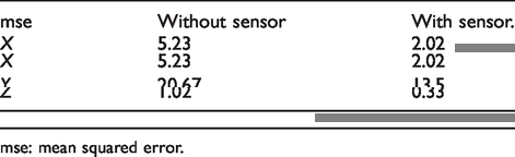
mse: mean squared error.
Conclusions
This paper has presented an aerial system for vertical surface contact with a MAV. For the contact, a two DoF robotic arm is attached to the MAV. To achieve the contact, we have developed a GS-PID controller. The gains chosen for the GS scheme have been obtained by studying a set of perturbation cases in two stages: (i) during arm deployment, whose movements induce perturbations on the MAV; and (ii) when the MAV approaches the vertical surface, whose perturbations derived from the air that hits the surface and returns to the MAV, this is known as the wall effect. For each case, we observe how the perturbations affect the MAV in a given position during flight, either during hovering or when flying toward the wall. We observe the MAV’s and ARM’s position by using the motion capture system VICON. The distance between the surface and the wall is measured with a sonar-based distance sensor.
Therefore, in contrast to initial approaches on aerial manipulation that have focused only on the stability of the vehicle when the arm is moving,2,13,23,40–51 in this work, we have also addressed the case when the arm makes contact with a vertical surface, interacting with it (drawing on the surface).
The primary goal of our approach has been to design a control strategy capable of mitigating the perturbation induced by both, the arm deployment and when flying close to the surface, thus enabling stable flight of the MAV.
A video of this work can be watched at https://youtu.be/ZDL6DdMxsj0
In sum, a GS-PID control algorithm has been developed considering the MAV and its manipulator as separate systems. The friction of the end effector with the surface and the oscillation of the system in the z-axis due to the added weight will be addressed in the future work.
Another aspect to be looked into is the removal of the motion capture system to perform the aerial interaction. We have reported preliminary results in this avenue, 52 aiming at performing aerial interaction in GPS-denied scenarios.
Supplemental Material
sj-pdf-1-mav-10.1177_1756829320938745 - Supplemental material for Vertical surface contact with a Micro Air Vehicle
Supplemental material, sj-pdf-1-mav-10.1177_1756829320938745 for Vertical surface contact with a Micro Air Vehicle by Aaron Lopez Luna, Israel Cruz Vega and Jose Martinez-Carranza in International Journal of Micro Air Vehicles
Footnotes
Declaration of conflicting interests
The author(s) declared no potential conflicts of interest with respect to the research, authorship, and/or publication of this article.
Funding
The author(s) disclosed receipt of the following financial support for the research, authorship, and/or publication of this article: The first author is thankful to Consejo Nacional de Ciencia y Tecnología (CONACYT) for the scholarship (No. CVU553682).
Supplemental material
Supplemental material for this article is available online.
References
Supplementary Material
Please find the following supplemental material available below.
For Open Access articles published under a Creative Commons License, all supplemental material carries the same license as the article it is associated with.
For non-Open Access articles published, all supplemental material carries a non-exclusive license, and permission requests for re-use of supplemental material or any part of supplemental material shall be sent directly to the copyright owner as specified in the copyright notice associated with the article.