
Abstract
This work addresses the problem of semi-automatic inspection and navigation in confined environments. A system that overcomes many challenges at the state of the art is presented. It comprises a multirotor able to inspect an industrial combustion chamber thus working in a GPS-denied environment with poor lighting conditions, in the presence of magnetic and communication disturbances, iron dust and repetitive patterns on the structure walls. The presented system is able to pass through narrow entrances but still capable of acquiring high resolution images and to allow operators to perform inspection of the structures. Starting from the captured data, the system is able to provide a 3D reconstruction of the inspected environment for offline analysis.
Keywords
Introduction
Maintenance is an important aspect that requires periodic control of equipment, systems, machineries and infrastructures. It is defined by the European standard (prEN 13306, 1998) as “Combination of all technical, administrative and managerial actions during the life cycle of an item intended to retain it in, or restore it to, a state in which it can perform a required function”. Depending on the objective of the maintenance activities, such a process can be distinguished into five main categories: preventive maintenance; predictive maintenance; corrective maintenance; zero-hours maintenance and periodic maintenance. Common goal of all these procedures is to avoid unexpected failure/inefficiency. Indeed, an effective maintenance program is fundamental to improve equipment life and possibly avoid unplanned maintenance activities. Unfortunately, any maintenance program is in general time consuming and costly. In the industrial field for example, maintenance process could require plant downtime and service interruptions.
Periodic visual inspection is in general the first step performed in any industrial maintenance program to detect typical defective in the materials status such as, among others, corrosion in iron and steel components, cracks in building walls and chimneys, etc. These inspections are typically done by experienced surveyors employing eyesight or special contactless measurement devices like for instance thermal/multispectral camera if required.
Although simple in principle, such operations are complex and time consuming since surveyors need some facilities (e.g. scaffolding) that allow him/her to be at a close distance from the inspected structure. Furthermore, such inspections are carried out numerous times in hazardous environments or in confined spaces, where the access is usually difficult and the working condition turns out to be extreme for a human being.
Taking into account the former considerations, it is evident that the introduction of any automation into the inspection process can improve a lot the safety of the operator and hopefully it can speed up the failure reaction chain. According to the International Federation of Robotics (IFR) “A service robot is a robot which operates semi-or fully autonomously to perform services useful to the well-being of humans and equipment, excluding manufacturing operations”. Service robots in general, assist human being performing repetitive jobs in dirty, distant or dangerous environment.
Typical examples here are climbing robots used to inspect walls 1 or metallic structure. 2 However, in the last decade, the interest of the European Community on the Aerial service robots research field has grown a lot.3–5 The aim here is to use Aerial Vehicles in real applicative scenario to support or replace human operators in all those activities that are either repetitive or dangerous for the human beings. More recently, the research community moves towards applications where the aerial vehicles are used as systems to interact with the environment and collaborate with other units to accomplish robotic tasks such as assembling or manipulating an object.6,7
Satler et al. 8 presented a system for remote visual inspection of indoor environment employing a micro aerial vehicle (MAV) endowed with embedded computing power. Initial tests were performed on an indoor office environment. The device has been proposed as operator replacement for a first and safe inspection process in order to detect surface damages and/or decide if additional intervention is required.
In a later work, 9 we extended the indoor inspection task with the ability to explore multiple floors buildings introducing a floor recognition and level merging algorithm.
In this work, we extend the previous systems introducing solutions to allow a complete industrial inspection task in a confined yet dangerous space. The scenario taken as reference is a non-structured industrial boiler, which is basically composed by a big combustion chamber covered by pipes that has to be verified by the maintenance process. The system here presented is able to locate itself and navigate efficiently in the environment in order to complete an industrial maintenance task in such kind of scenarios. A collision avoidance procedure allows the system to correct desired trajectory while avoiding collision with the external structures or objects moving in the environment.
The rest of the paper is organized as follows. The next section presents related works at the state of the art in the fields of industrial inspection and robot localization. Then the following section introduces a reference scenario that has been used to define project requirements and to demonstrate the capabilities of the developed system. In the subsequent section, the hardware and software components of the overall system are presented. This is followed by a section which discusses about developed control system algorithms for the localization and mapping of the robot in the environment. Then, the user teleoperation interface and the automatic MAV navigation module are discussed. Then, we present some post processing technique to obtain inspection information that can be analyzed offline. The preliminary evaluation flight test performed inside an industrial combustion chamber is presented. In the last section, the main conclusions are drawn.
Related work
MAVs have become increasingly popular for autonomous navigation in unstructured environment thanks to their agility and fast dynamics compared with ground robots. There are several works focused on inspection tasks developed in the recent years; early works appeared in the literature were based on visual inspection without any contact with the environment, while recently works founded by EU projects proposed contact-based approaches.6,10
In Luque-Vega et al., 11 a quadrotor is used for high voltage power line inspection. The system payload is composed of a thermal infrared and a color camera for the inspection purpose and a GPS, IMU and altimeter for navigation capability. The vision algorithms, however, run on a remote ground control station in order to detect real-time anomaly/defect alarms.
In Bonnin-Pascual et al., 12 an MAV is used to visually inspect vessels in order to detect cracks and corrosion in the metallic structures. The solution is based on supervisory autonomy, i.e. the surveyor controls the inspection process teleoperating the vehicle which in turn is provided with on-board algorithms to ease the navigation and control from unexperienced people.
In Gohl et al., 13 a first attempt driving an MAV in underground mine field is presented. The system is based on a hexacopter endowed with Skybotix visual-inertial sensor and 2D laser scanner used to collect data during a manual flight. A 3D environment reconstruction is then performed off-line evaluating the quality of the acquired data as well as of the localization process.
In Nikolic et al., 14 an MAV endowed with an integrated visual-inertial SLAM sensor is employed for industrial boiler inspection. This work uses a front looking stereo camera and an IMU to estimate the vehicle pose and navigate inside the industrial boiler following a reference trajectory.
In addition to the aforementioned applications, such devices have proven their flexibility in many other fields including but not limited to agriculture,. 15 search and rescue, 16 exploration and mapping, 9 dam inspection, early fire detection and forest protection, traffic monitoring, aerial photography, surveillance and reconnaissance, chemical spraying and entertainment industry and filming. A detailed analysis for civil application has been provided in Sarris and Atlas. 17
Each system mainly differs for the platform autonomy level, i.e. how much computation is empowered to the ground control station supporting the vehicle, the sensor payload and the assumptions about the environment knowledge, i.e. structured/unstructured or known/unknown. Typical navigation sensor suites are based on GPS, laser scanner, infrared or ultrasound sensors and more recently on camera. This latter solution represents the richest data supplier combined with low weight and low prices (compared to lasers) at the cost of increased computational cost required to run vision algorithms.
Simultaneous localization and mapping (SLAM) 18 algorithm is a fundamental component constantly present on each platform used in real application domain. Graph-based methods 19 or probabilistic methods 20 have been proposed by the research community in the last three decades. Recent works on SLAM on the other hand, referred as visual-SLAM or vision-based navigation in the literature, are based alternatively on features tracking using either a mono or stereo frontal camera,21,22 or a ground-looking camera 23 and on direct methods. 24
Although promising and accurate, the outcome and the robustness of all vision-based methods strongly depend on two assumptions: (i) enough lighting conditions and (ii) environment texture richness. While the former assumption can be met using custom designed lighting systems, the latter is likely to fail in real scenarios that are generally characterized by repetitive elements or that are poor in texture features.
Power plant boiler inspection
The proposed solution has been designed considering as reference task the inspection of the interior part of a thermal power plant boiler.
The boiler is classified as confined space and it basically consists in a big combustion chamber completely covered by pipes transporting water for the steam production. Later on, the “wet steam” passes through the superheater, the reheater and the economizer to improve the energy exchange efficiency.
Maintenance task is typically divided into daily, weekly, monthly, semi-annual and annual tasks. Portholes along the whole structure are used during frequent and elementary inspections, e.g. daily, weekly, to access corresponding points of interest. Semi-annual and annual maintenance routine on the other hand, is performed entering into the boiler from the bottom part.
In the latter case, it is required to stop the steam production process in advance, wait the required time to decrease the temperature and then wash the combustion chamber. When the environmental condition is feasible for a human being, the bottom part of the boiler (64 × 64 cm entrance) is used to access the interior and hence start setting up scaffolding structure to get close to the structure to inspect. Obviously, this is a long process and demanding for the worker first and the surveyor later.
The employment of an MAV allows to localize loses which in turn will speed up the intervention time. Such devices provide easy and fast ways to detect surface damages allowing to study the most convenient intervention strategy, to prepare all the materials and to schedule the maintenance intervention in advance. Finally, yet importantly, the employment of such a technology will improve the surveyor working conditions.
The target of the inspection is the combustion chamber, which is composed by a parallelepiped of 7.6 × 11×21 m, see Figure 1. The other parts of the boiler have too many obstacle and few free-spaces for an MAV safe flight.

Section of the boiler chamber and details of the pipe structures. (a) Entrance of the chamber (funnel-shaped portion). (b) Pipes wall.
Requirements
The system requirements have been drawn taking into account both the operators experience and preliminary real field tests.
Considering the goal of the proposed system, i.e. provide a mean for tele-visual inspection, the preferred vehicle flight characteristics are: the vertical take-off and landing (VTOL) capability; the possibility to perform stationary flights and low-speed movements without compromising the flight stability; allow indoor flight as well as provide robustness to accidental contact with the structure being considered within the inspection process. These requirements rapidly discard fixed-wing platforms since they do not allow VTOL capability and require a minimum velocity to guarantee vehicle lift. The indoor flight requirements discard vehicles powered by combustion engines which, moreover, are not suitable to flight in most of the confined spaces characterized by fire and explosion risks. All these aspects focus the search on electrically powered MAVs in the form factor of quadrotor or hexarotor that can be designed with ducted fan in order to guarantee robustness for unwanted environmental collision. Moreover, the ducted fan vehicles reduce hovering power consumption. 25
Regarding the sensor payload, it is worth noting that most inspection tasks are usually performed in GPS-denied environment which on the other hand cannot be structured since this activity is in general practically not feasible or it will vanish the benefit introduced by the aerial service robots usage. For this reason, the aerial platform has to estimate its own state relying only on embedded sensors and on-board computation resources.
From the end-user point of view, the proposed system has to be as user friendly as possible and in theory it should allow unexperienced pilots to fly the system in complex and cluttered environment. To this end, the system has to provide the pilot with assistive control features able to implement shared control capability, e.g. follow a line or move towards a point of interest. However, one of the main requests from the operators is to let the human in control of the inspection avoiding to completely automate the task. The main rationale under this request is the possibility to exploit the cognitive capability of the human being and in particular, the experience gained over the years by the surveyor that will guide the inspection process focusing on critical points.
Challenges
Given the partial or total enclosure of confined spaces, GPS technology cannot be reliably used, and this requires solving the localization problem employing other sensing technologies. GPS-denied environment has been addressed in the past relying on vision-based localization. 26
Many times, industrial settings are surrounded by metallic structure or elements and these could interfere with electromagnetic signals and sensors. In particular, within the boiler scenario, the presence of pipes, tubes and similar elements greatly reduce the quality and the bandwidth of wireless communication and the reliability of compass in IMU sensor used to stabilize the vehicle. The former constraint does not allow to close the control loop externally exploiting high-power computing unit. Hence, on-board computation requires automatic behaviors to overcome rapidly collisions and flight stability issues. Thus, the need of efficient algorithms runs with good performances on embedded hardware without consuming much battery power.
In addition, the boiler scenario presents (i) variable air pressures that limits the use of barometric sensors to estimate for instance the altitude of the robot, (ii) the presence of dust (iron dust in the case of combustion chambers) could generates visual occlusions, visual feature outliers and also interfere with the electronic equipment, (iii) lack of light which reduces vision algorithms performance requiring a custom designed illumination system.
Finally, yet importantly, typical industrial settings present repetitive textures and elements that affect correct data association of visual features in algorithms at the state of the art.
This work presents a system that overcomes all the challenges and limitations discussed above employing specific solutions to each problem. We have chosen a foldable MAV as hardware platform but with good payload capabilities, that make use of laser sensors for localization and navigation that are not affected by visual artifacts as could be the case for classical camera systems. The MAV is equipped with an illumination source, high-resolution cameras for inspection analysis and all the control algorithms runs on an embedded ARM-based control board. To obtain real-time performances on an embedded computing platform, a custom performant SLAM algorithm has been developed. 27 To estimate altitude inside confined chambers, two sets of sensors have been used, ultrasonic for proximity sensing and camera based for long range sensing. The communication between the MAV and the ground station is reduced to small footprint high-level control packets for inspection guidance. Moreover, the system here presented was designed to work in unstructured environments. This means that the proposed system does not require a specific environment nor external sensing unit (like markers for instance) to accomplish inspection tasks.
System description
The proposed system is composed of two elements. The first element is constituted by a portable computer used as operator control unit (OCU) in order to give high level teleoperation commands to guide the inspection task (see ‘Teleoperation interface’ section). The second element is an MAV equipped with an embedded processing board and a suite of navigation and inspection sensors. According to the previously discussed requirements, the selected vehicle is a ducted fan quadrotor designed by Cyber Technology (CyberQuad MAXI). It is a quadrotor equipped with four brushless motors suitable to be used in critical environments (presence of flammable gases) since they do not produce sparks. The device has highly optimized ducted fans, allowing the platforms to be less than half the size of a helicopter rotor, with the same lifting efficiency. The protection allows easily flight through doorways, down hallways and through tight spaces without risking a rotor strike. The MAV dimension is 69 × 56×20 cm.
The CyberQuad MAXI is provided with the Navy control and Flight control from MikroKopter which embeds a fast motor controller and an IMU composed by three single axis gyro on all three axes (ADXRS610), three-axis accelerometer (LIS344ALH), barometric pressure sensor (MPX4115A) and a compass (HMC5843). The installed custom payload is composed by the following elements. A front mounted Sony camera (HDV-CX350VE) allows visibility over large elevation ranges and it is used by the remote operator for inspection purpose. In fact, the camera output is streamed throughout the Wifi link by means of a USB grabber (EasyCap DC60). The camera is mounted on a pan-tilt base which automatically stabilizes the pan with respect to the horizontal direction and allows the user to adjust the tilt towards the desired direction. Moreover, the optical camera zoom (12×) is remotely controlled by the operator as well. Near the camera, a custom illumination system has been designed by means of several LEDs which assure the adequate amount of light for the inspection task. Two sonars (XLMaxSonarEZ4), one on the top and one on the bottom of the device, are used to detect upper and lower obstacles as well as to measure distances from the ceiling and the ground during the automatic ascending inspection flight and the takeoff and landing procedure, respectively.
In the case of high elevation industrial environments, the sonars are replaced by long-range distance measuring camera sensors (Leddar M16) without the need of modifying the algorithmic structure of the system. For the localization purpose, the environmental mapping and the fusion algorithms, able to improve the attitude estimation, a Hokuyo laser (UTM-30LX) has been mounted on the top of the device. All these components have been powered and interfaced with a Pandaboard by means of a custom electronic board which provides the required voltage regulation as well as the levels transition. The Pandaboard is the computing unit of the system and it is also responsible for the external communication with the OCU ground station. Table 1 summarizes major design information.
Characteristics of the proposed MAV system.

The PandaBoard is a low-power, low-cost single-board development platform based on the Texas Instruments OMAP4430 which features a dual-core 1 GHz ARM CortexA9 MPCore CPU, a 304 MHz PowerVR SGX540 GPU, IVA3 multimedia hardware accelerator with a programmable DSP, and 1 GB of DDR2 SDRAM. The connectivity is provided by wired 10/100 Ethernet as well as wireless Ethernet and Bluetooth. It also has two USB host ports and one USB OnThe-Go port, supporting USB 2.0. In our system, the device runs Ubuntu Linux distribution.
Framework architecture
The system can be operated with high level commands by an operator for inspection purposes or alternatively, by an automatic navigation component that uses a harmonic potential field (HPF). To maintain a stable flight during the inspection task, the system acquires information from the environment by means of a laser range finder (LRF) and two distance measuring sensors. This information is processed by an SLAM component that feeds the current position and the asset of the MAV to the navigation and the low-level control components. In parallel, a collision avoidance element, independent from the SLAM algorithm, is responsible for avoiding collisions with external objects. The underlying components of the software system are depicted in Figure 2.

Software components relationship diagram.
The sensor acquisition and the algorithm computation are performed by the embedded computing system, i.e. the PandaBoard. The next sections will introduce and discuss each module component in detail.
Control algorithms
This section introduces the MAV dynamic model employed to design the low-level control algorithms, the global and relative reference frames for the equations of motion, the algorithm responsible for the localization, mapping and feature extraction procedures and finally the velocity estimation and collision avoidance algorithms.
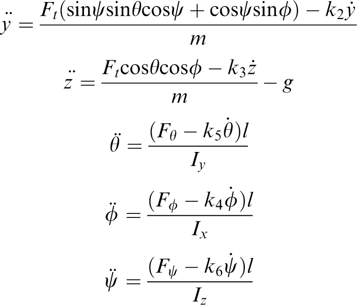
Dynamic model and low-level control
The dynamic model used for the analysis and development of the control algorithms is a simplified model based on the work by Martinez.
28
Considering the world and the robot reference frames as in Figure 3, if we define with 

MAV reference frame (body frame) on the left and World reference frame (absolute frame) on the right. The reference frames follow the right hand convention. MAV: micro aerial vehicle.
Transfer functions for the roll, pitch and yaw responses, taking into account also the embedded flight control board response, have been modeled with a Box–Jenkins model 29 resulting in first-order systems.
The low-level control has been implemented decoupling the x and y axes motion. For the pitch and roll angles, the control systems are composed by two feedback loops. The outer loop is responsible for the regulation of the maximum velocity of the vehicle as a function of the distance from the reference input, while the inner loop regulates the asset angle (pitch or roll) taking as reference the velocity computed from the outer loop. For the yaw rate, the control system is composed by a single loop that regulates the angular velocity of the vehicle to follow a reference angle. Each control loop has been implemented with PID regulators. In particular, the low-level control of the pitch angle takes into account also the presence of a bias that is present in the real system and changes at each switching on/off of the vehicle. Without a manual compensation of the bias, the low-level control provides a compensation strategy in the first few seconds after takeoff.
SLAM
The proposed system localizes itself in the environment by means of two independent SLAM algorithms which will be discussed within the following sections. The first SLAM algorithm is used to estimate the pose of the MAV on a plane, while the second SLAM algorithm is used to estimate the altitude of the MAV. Fusing both the information, the complete 3D pose of the multirotor can be obtained.
Rao–Backwellized particle filter
The Rao–Backwellized particle filter (RBPF)
30
is a Bayesian filter method, which approximates the posterior probability by a set of sample particles drawn from the posterior. In such a framework, each particle represents a robot path and a map. The key idea of RBPF is to decompose the joint posterior probability into a posterior probability of the map 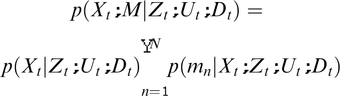
Hence, the posterior probability of the trajectory is computed by a particle filter and then the map is updated according to the current measurements and the trajectory posterior contribution.
Map representation
As mentioned before, the map
Using the Hessian representation (Figure 4), the wall coordinates are given by the triplet
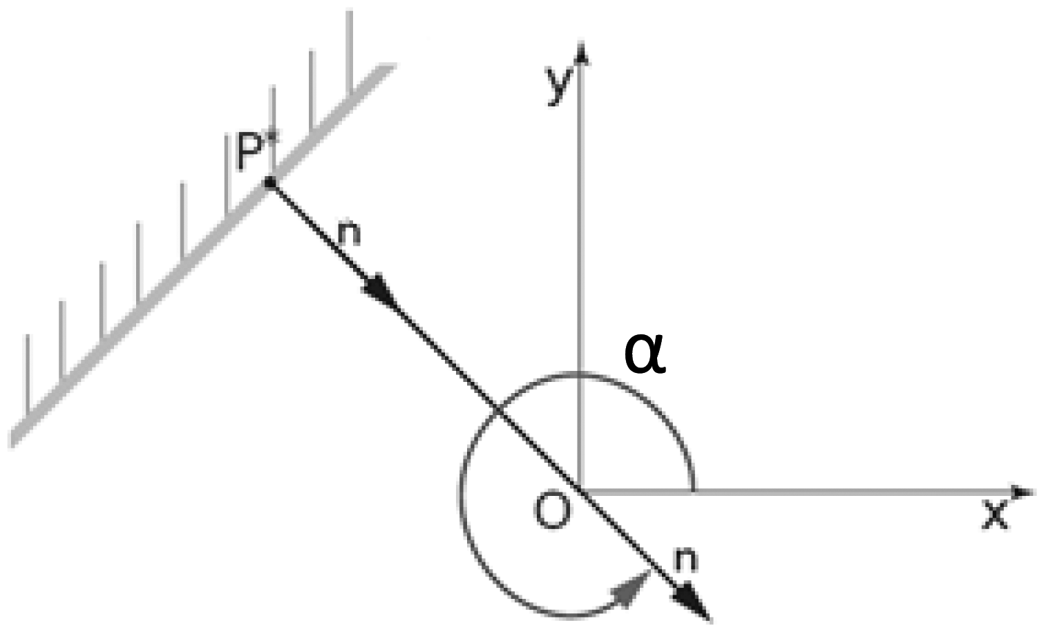
Hessian representation of wall coordinates with respect to the frame O

Embedded SLAM algorithm
The SLAM algorithm here presented is used to determine the robot pose on a plane

Schematic view of MAV inspection operation with laser and altitude sensors for SLAM purposes. Here the wall made of tubes resembles the interior of an industrial combustion chamber. MAV: micro aerial vehicle; SLAM: simultaneous localization and mapping.
Fusing the particle filter robot pose estimation on a 2D map with an estimation filter of the altitude (‘Altitude estimation’ section), the complete pose estimation can be obtained.
Overview of the Embedded SLAM algorithm


Each algorithm cycle starts from the state obtained from the previous step and incorporates the input
In the following sections, the algorithm key points are discussed.
Pose prediction
To predict the MAV pose, data available from the embedded IMU are integrated in an odometry model. Without considering thermal drift terms, we can write the relationship between raw IMU readings and true signals as

It is possible to write the accelerations in the world frame following the matrix transformation
32

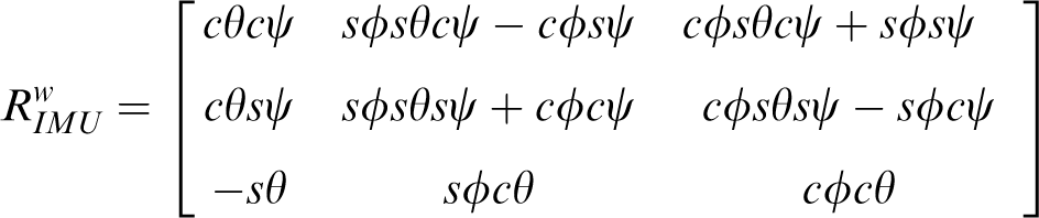
In the previous equation, c and s state for the cosine and the sine function, respectively, and
We can thus write the prediction for the kth particle as

The covariance of the robot pose is set equal to the covariance of the Gaussian white noise that models the measurement error of the IMU sensor.
Feature extraction
Having at disposal an embedded computing unit, and considering the need to process a large amount of laser range data, an abstraction layer has been developed. This layer represents a virtual sensor that produces high level data starting from raw laser range readings. This high-level data are usually called features or landmarks in mapping literature. As discussed above, the Hessian representation of walls has been selected as appropriate feature for confined space inspection purpose. To be able to detect features, our implementation starts from the Split and Merge algorithm
33
that is a fast and performant solution to the problem. With respect to the original implementation, we introduce filtering kernels to obtain a more reliable and precise measurement. In particular, five filters have been designed and are applied at the output of the Split and Merge algorithm:
The correspondences between the detected features and the already known landmarks are found using maximum likelihood (line 4 of SLAM algorithm overview). If the obtained likelihood is under a certain threshold
Figure 6 shows the outcome of the proposed algorithm compared with the standard Split and Merge algorithm. The result of the standard approach is depicted in blue, whereas the refined outcome after passing the filtering stage is depicted in red. The algorithm reconstructs four segments whose details are shown in the right part of the figure.

Output of the split and merge algorithm with custom filtering.
It is worth to point out that the detected features are compute with respect to the MAV reference frame. If global mapping is required, a transformation into the global map reference frame is required.
Finally, note that the threshold
Measurement model
Prediction target response for planes
34
is used to predict the LRF measurement. We consider the feature
The measurement prediction 

On the other hand, the Jacobian 
Resampling phase
The importance resampling step is performed with a classic low variance sampler.
20
Before such a step, the unreliable particles features are removed by means of a visibility counter and a threshold. If a measurement is not associated with any feature in the particle map, it is considered as a new landmark and its visibility counter is initialized such as
On the other hand, when a feature is associated to a detected landmark, its counter is incremented keeping it alive (
In order to remove unreliable features, at each cycle, every visible particle has its counter decremented. When the particle visibility counter goes under a certain threshold, the feature is considered unreliable and removed.
Velocity estimation
To reduce the computational time of the implemented SLAM algorithm, the vehicle velocity estimation is performed by an EKF. In this way, the estimation is performed once using the output of the SLAM algorithm and not inside each particle, thus reducing the particles dimensions and the computational time. The dynamic equations involved in the prediction step are the following

While the position is expressed with respect to the global reference frame, the velocity is computed with respect to the vehicle body frame
The correction step uses as sensor the output of the SLAMCGS algorithm and adds a Gaussian noise
Collision avoidance
For safety purposes, the system has been equipped with an algorithm estimating the distance of the MAV from the obstacles. This module is independent from the localization module and it computes both the objects distance and approaching speed exploiting the laser sensor. In particular, the sensor span (270 degrees) has been divided in six regions (45° each) in which the minimum distance measure
The approaching speed (
The sensor used in the correction step is the obstacle sensor that provides the minimum distance from each obstacle (
Considering the state vector of the EKF filter, for each sector 
Based on this value, it is possible to decide if the MAV is in safety or if there is a possible danger and the system should intervene to prevent collisions with the environment.
Considering Figure 7, if

Time to collision graph and thrust vectors.
Altitude estimation
As pointed out in the challenges description, the barometric sensor readings are affected by the temperature gradient of the environment. This, in turn, results in a low-precision accuracy estimation of the altitude. Moreover, estimating the altitude by means of a Kalman Filter and a downward looking sensor is not robust since the drone can fly over obstacles or even a non-flat ground.
For this reason, in the proposed system, the drone height is computed from upwards and downwards looking sensors data using an SLAM algorithm consisting of Kalman filters. The altitude estimation method firstly designed for an indoor multi-floor building exploration, 9 adds upwards looking sensor data to the formulation by Gronska et al. 35 As anticipated in the hardware description (‘System description’ section), the system can be equipped alternatively with sonars sensors or with long range camera sensors. The camera sensors option allows greater range of distance measurement and is composed by an embedded module containing both a camera and an LED emitter. The Leddar M16 sensor does not provide punctual information but measures distances of objects within 16 sectors of 2.8° aperture from the camera viewpoint. We can consider both sensors equivalent from an algorithmic point of view.
The first step of the algorithm is to compute the drone height and vertical velocity according to the model prediction, as detailed below

Then, the ground and ceiling elevation beneath and above the drone are predicted according to the measurement prediction

The next step is to find the matches with the already known levels close to the robot current pose (the set of corresponding levels C). Once obtained the matches, those are merged into a single level elevation. Each level is represented in the levels map L by its own pose
To merge N levels from C, one can prove that it can be achieved using the next equation

After merging the levels elevations, the drone altitude and the current levels elevations beneath and above the drone are updated as follows.


Updating the drone altitude and levels from the ceiling measurement, implies to modify the above equation such as

Once updating the drone altitude, the elevation levels are updated using for each one a Kalman filter. Then, the new levels are inserted into the levels map L.
Eventually, the final step of the algorithm aims to merge closest levels. It only considers the levels close to the current drone pose. Afterward, within this subset, the algorithm compares the difference between the levels elevation, if it is under a certain threshold
Navigation
Once the localization problem has been solved, the environment navigation and thus the inspection procedure can be addressed. Two navigation modalities have been proposed: (i) teleoperation modality – the operator drives the system with high-level commands using the custom designed OCU; (ii) autonomous modality – the MAV navigates autonomously the surroundings using a HPF in order to have a full coverage of the environment to be inspected.
Both the approaches are introduced in the following paragraphs.
Teleoperation interface
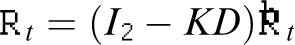
To provide high-level teleoperation functionalities for personnel without expertise in drone flight, the system is equipped with an OCU that allows the user to guide the inspection task via a simple interface. In particular, the operator can use a joystick to command the direction of motion of the MAV and a display shows both the captured video stream, the reconstruction of the local map and, if selected, internal algorithm parameters (see Figure 8).
Operator control unit displaying frontal camera views with current laser scan and MAV asset parameters of the internal SLAM control as well as estimated features and collision distances. MAV: micro aerial vehicle; SLAM: simultaneous localization and mapping.
The OCU has been designed in order to allow the operator to perform the inspection from a remote and safe location. The OCU is composed by a Notebook which runs the developed graphical user interface (GUI) and a joystick which is used by the operator to move the camera point of view as well as to set the desired device pose and to control the remote functionalities (like for instance starting/stopping video recording, modify the camera zoom, or select inspection points of interest). By means of the joystick, the operator can also move a virtual point which is then followed by the vehicle control system satisfying additional safety constraints (obstacles avoidance and device autonomy). The GUI has been realized by a C++ based Qt (Digia) application and it is composed by two main windows that can be arranged on the screen in a custom way. On the right side of the windows, all the information related to the vehicle, like for instance the estimated position and velocity, are shown. The current map and the measured features with respect to the device position are also presented in a polar view. The two windows have been specifically designed for the two operators that in general perform the inspection. One is in charge for the visual inspection, whereas the other controls or supervises the MAV navigation aspects.
Virtual potential function for autonomous exploration
To allow some degrees of autonomy during the environment exploration and to leverage the operator effort during the inspection task, the system implements a potential field based path planning algorithm, firstly introduced in Khatib. 36
Among the possible approaches in literature, in frontier-based exploration 37 methods, the frontiers represent the borders between the known free space and the unknown environment. These are computed using algorithms that are similar to edge detectors. Eventually, the robot moves towards the nearest frontier following the shortest path that avoids obstacles computed with a best-first search algorithm. 38 In Kim and Eustice 39 the robots perform a default policy exploration based on the Boustrophedon motion40,41 and revisits the interesting areas based on their visual saliency following a path defined again by a best-first search algorithm. In Shen et al., 42 virtual gas molecules are used to detect unknown areas, these particles move toward free and unknown space with a Brownian motion, colliding with already known obstacles. Once detected, the robot moves towards the navigation goals. Finally, in Silva et al., 43 a potential field is incrementally computed using harmonic functions where unknown areas have an attractive potential, whereas obstacles have a repulsive potential. Therefore, the robot is attracted towards the nearest unexplored space.
The approach presented in Silva et al. 43 has been selected as exploration policy for its efficiency, easy implementation and above all because it avoids the use of best-first algorithm which can be time-consuming if the goal is far from the robot. The algorithm employs harmonic functions 44 to solve the local minima issue. 45
Harmonic Potential Field Based Exploration

Starting from the estimated environment map, the potential field is updated within a sliding window, centered on the MAV. This means that cells which belong to the circle of a certain radius R centered on the robot pose have their potential updated. The ones with a high occupancy probability (above a certain threshold) are considered as obstacles and therefore their potential is set equal to 1. The free cells are updated according to the Gauss–Seidel method while taking into account cells at the borders. This procedure is repeated until a certain accuracy is obtained.
At the beginning of the exploration, all cells have their potential set equal to 0, and therefore unknown areas are cells which have never been updated inside the sliding window, they represent navigation goals and the robot is attracted to them. As suggested in Shade and Newman, 47 the potential value of the cell containing the robot is set equal to 1 (line 4).
Once reaching the desired accuracy, the negative gradient is numerically computed. Eventually, in order to follow an optimal path towards the goal position (unknown space), a gradient descent method as described in Gupta et al. 48 has been adopted.
Post processing and structure reconstruction
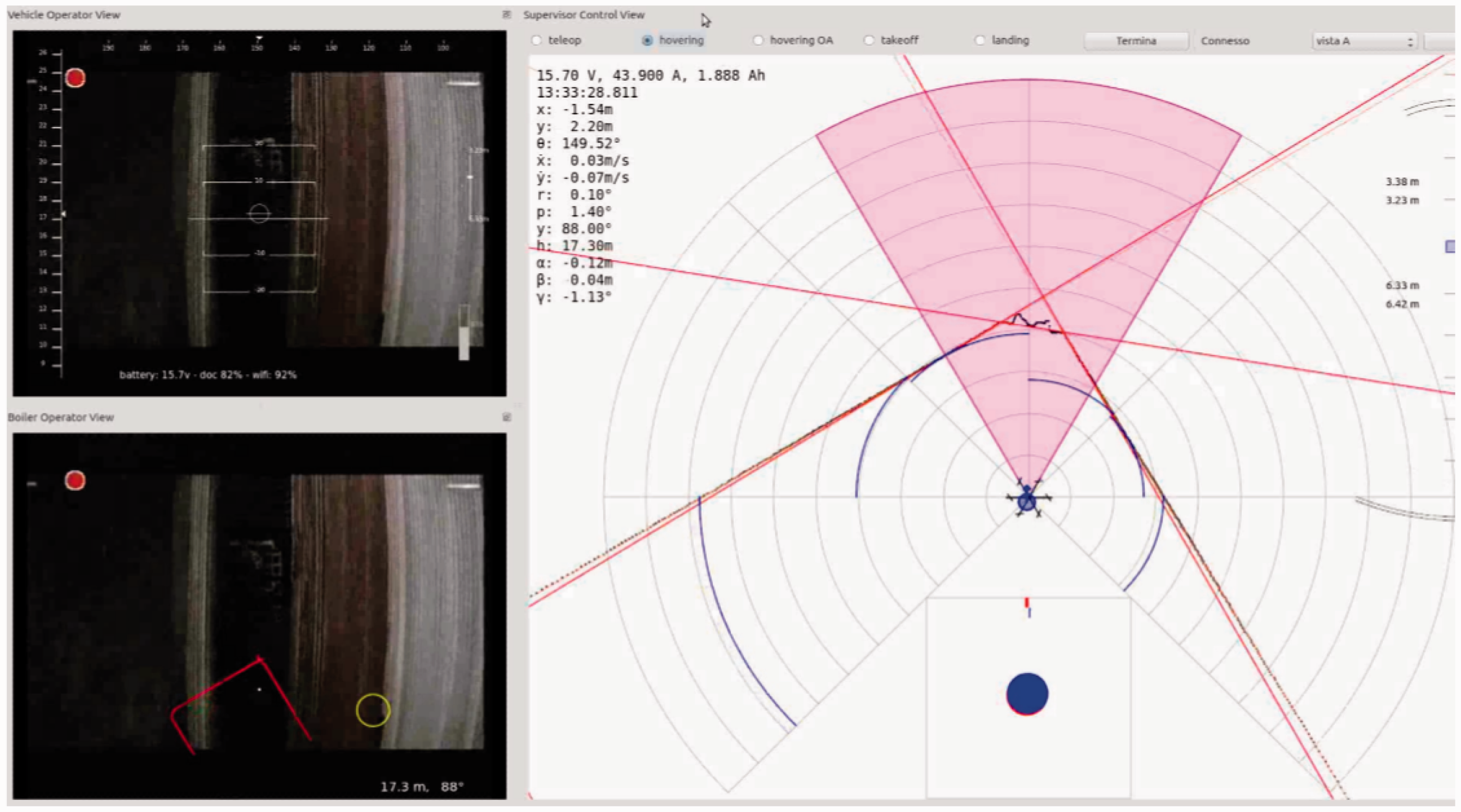
The elements and features to inspect can be various depending on the environment itself. For this reason, we did not focus on the inspection features that can be assessed by qualified personnel through visual inspection. Having at disposal all the information of the mapping and localization algorithm is however possible to generate offline a 3D model of the explored environment for detailed analysis. It is in fact possible to associate frames captured by the frontal camera with the reconstructed positions of the MAV, and thus generate a 3D Mosaic of images, or better to employ an offline optimization technique known in literature as structure from motion (SfM) 49 and create a complete 3D reconstruction of the environment. An example of reconstruction of a sector of pipe wall captured inside an industrial boiler is shown in Figure 9.
Estimated trajectory during an inspection and SfM reconstruction example of a sector of the environment from 50 frames. SfM: structure from motion.
Test flight in an industrial combustion chamber
Several test flights have been carried out inside industrial combustion chambers to verify the robustness of the system. In this section, a preliminary test flight is presented and discussed. The goal of the preliminary demonstration flight was to prove the effectiveness of the semi-autonomous aerial vehicle in the execution of an inspection task concerning a combustion chamber's conditions. The main sensor used to conduct the inspection was a camera in the visible light spectrum.
In details, the task consisted in a visual analysis of a boiler's internal wall and of the burners’ rows that are located on the internal edges of the chamber.
The chamber was already prepared by means of an internal scaffolding to provide a takeoff platform for the vehicle. This platform should have been placed immediately above the funnel-shaped portion of the chamber; instead, the scaffolding was installed around 5 m below the hopper.
Before the actual flight, proper communication between the vehicle and the OCU has been verified. A brief test flight has been conducted to verify overall system correct functioning. Unfortunately, random interruption in the WiFi communication channel, likely due to the metallic structure of the combustion chamber has been noticed.
For the demonstration, a task sequence following the takeoff of the vehicle has been planned:
(1) An ascent phase to reach the hopper limit followed by an approach phase to the left edge of the chamber. (2) A following turn of the vehicle's camera (front of the vehicle) toward the burners and subsequent ascent of the vehicle up to 30 m (altitude reported by the vehicle's altimeter). (3) A second turn of the vehicle in order to have the vehicle's camera orthogonal with respect to the chamber's wall, to get best viewing condition and a descent to the hopper limit. (4) Horizontal movement on the right for some meters to scan another section of the chamber's wall. (5) These steps are repeated in order to cover all the wall surface. (6) If possible (enough remaining battery charge), scan of another burners row. (7) Coming back of the vehicle to the takeoff position and landing.
The takeoff maneuver has been carried out very carefully because of the unexpected dangerous presence of a banister. Anyway, the takeoff proceeded smoothly, thanks to the robustness of the localization algorithm.
After some seconds from the takeoff, necessary for the vehicle self-stabilization and dynamic parameters identification, the task advanced according to the task plan, so the vehicle has been controlled by the vehicle operator, using the OCU's keyboard, and brought near to the selected chamber's burners row. Once reached the planned position, the vehicle operator started to make the vehicle move as shown in Figure 10 following the scheduled sequence. It should be noticed that, during the flight, many random interruptions of the WiFi link have been encountered. However, these temporary lacks of communication did not compromise the overall good result of the task, but they diminished the total amount of time available for the actual inspection.

Test flight in an industrial combustion chamber. The intended sequence phases are shown. After take-off, phase (1) is an approach to the left edge of the chamber. (2) MAV turn and ascension up to 30 m. (3) MAV turn and descent. (4) Lateral movement. (5) The sequence of action repeats until the entire wall is inspected. MAV: micro aerial vehicle
Conclusion
The manuscript introduces the problem of semi-automatic inspection and navigation in confined environments with a special focus on demanding environments like industrial combustion chambers. A system that overcomes many challenges imposed by such a problematic environment is presented. The presented system is composed of a multirotor flying robot and a control ground station and allows a human expert to easily inspect an industrial facility. The main problems for such inspection task have been introduced in detail at the beginning of the manuscript. The proposed solution system is described both for what concerns the hardware selection and the algorithmic and control strategies. Some of the presented software components have been previously introduced by the authors and tested in indoor office environments. The same algorithms displayed equivalent efficiency in the industrial environment presented here. Thanks to the choice of a laser sensor for the navigation and localization part and of a small computational footprint SLAM algorithm, the system resulted robust to communication losses, air flow disturbances and presence of undesired obstacles inside the combustion chambers. The presented system allows non-expert MAV pilots to navigate an aerial vehicle inside an unstructured confined space and visually inspect the structural condition of the environment. While this is not the intended usage, starting from the captured data, the system is also able to provide a 3D reconstruction of the inspected environment for offline analysis. To increase the flight time and lower the overall inspection time, strategies should be investigated in the future in order to reduce energy consumption by means of reducing the MAV payload or introducing techniques to recover energy from the environment.
Footnotes
Declaration of conflicting interests
The author(s) declared no potential conflicts of interest with respect to the research, authorship, and/or publication of this article.
Funding
The author(s) received no financial support for the research, authorship, and/or publication of this article.