
Abstract
Multi-rotor unmanned aerial vehicles are unstable in headwind because of nose-up pitching moment generation and thrust degradation. Reducing the pitching moment generation could enhance the tolerance of the unmanned aerial vehicles to wind and improve cruise flight speed. In this study, a canted rotor configuration was proposed to reduce the moment in uniform flow and examined. The objective of the study is to evaluate the effect of moment reduction by canted rotors. First, flow interactions between rotors of the quad-rotor were visualized using a smoke wire method. Second, the moment reduction by canted rotors was estimated based on isolated rotor performance. Third, the moment of the quad-rotor varying the body pitching angle was examined using a wind tunnel. At an 8 m/s wind, when the body pitching angle is horizontal, slanting the rotor by 20° to outside the body degraded the moment by 26% compared with the parallel rotor configuration.
Keywords
Introduction
Multi-rotor unmanned aerial vehicles (UAVs) are the vertical take-off and landing aircrafts (VTOLs) with multiple rotors. Owing to advancements in electronic devices, rapid motor speed control and large capacity batteries have been realized in the last two decades. Small multi-rotor UAVs could be produced at low cost and used for applications ranging from hobby flyers to military drones.
The first multi-rotor configuration was developed in the 1920s. 1 In the 1980s, electric-powered multi-rotor UAVs were developed. Niwa and Sugiura developed a quad-rotor UAV using four ducted fans. 2 Studies on UAV control were applied in the field of studies on control and robotics in the 1990s. 3 The size of the multi-rotor UAV decreased in the 2000s. 4
Recently, UAVs are also being used for surveillance, inspection, and transportation. For example, UAVs could inspect wind turbines, 5 survey disaster sites to ensure the safety of rescue activities, survey a volcano after an eruption, 6 and inspect cracks in old highway bridges. 7 The most significant feature of UAVs is their ability to hover as VTOL. Compared with general small UAVs with fixed wings, the hovering and vertical take-off abilities of multi-rotor UAVs have made possible their use in an increased number of civilian operations.
Although multi-rotor UAVs could hover and are affordable for civilian operations, UAVs are unstable in wind, which is often discussed with respect to open air operations. 8 When flying in headwinds, the rotors of the UAVs generate a head-up pitching moment because of the flapping movement of the rotor blades and the differences in their local angles of attack (AOAs) and in flow speed to rotation blade. The moment affects the control of the pitching motion of UAVs. Thus, the posture of UAVs in wind is unstable compared with hovering in windless conditions.
Furthermore, the thrust of the rotors changes at different AOAs. The flow speed of passing rotors changes in relation to the main stream direction, which changes the inflow ratio of the rotor. Thus, the rotor thrust changes as the AOA of the UAV changes in the forward flight.
During forward flight, the rotors are tilted forward to generate forward force, and the thrust degrades because of increasing relative wind speed to the rotor. Multi-rotor UAVs control their posture and lift force by changing each rotor thrust. Therefore, a change in the thrust due to headwind affects posture stability. For these reasons, multi-rotor UAVs are unstable in headwinds. Thus, the ability to endure headwind is required for outdoor flight.
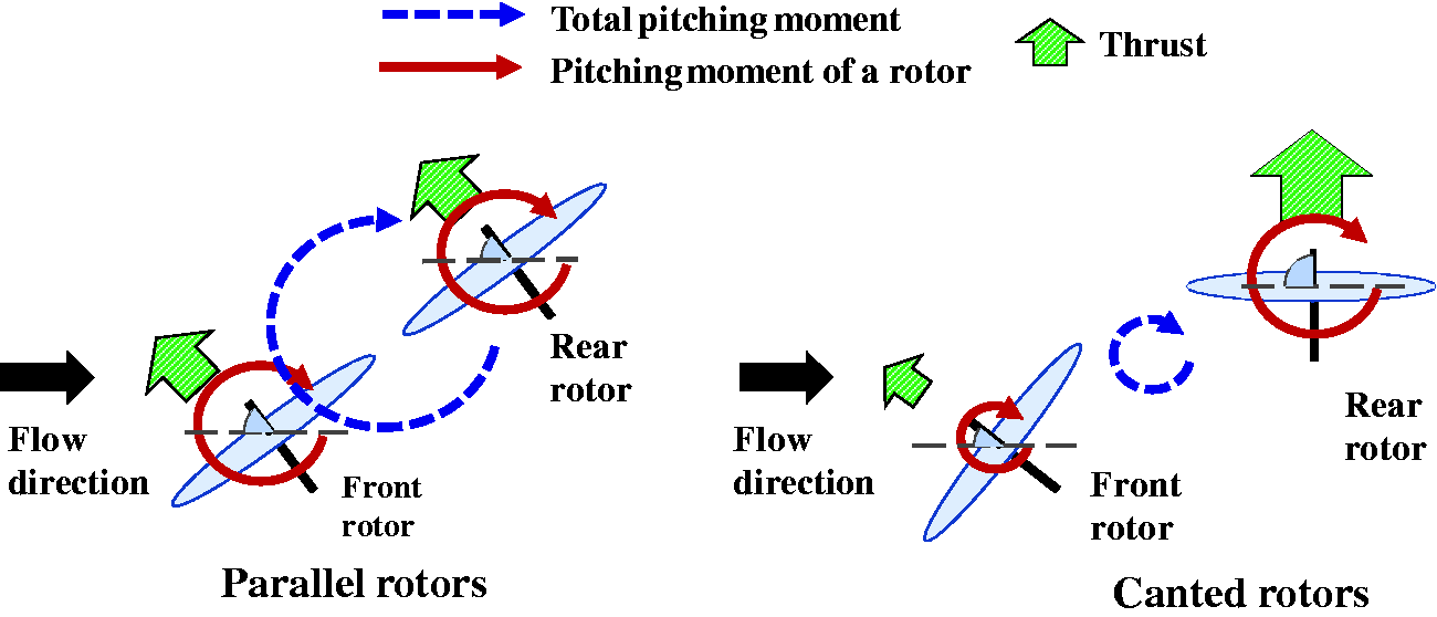
In headwind flight, multi-rotor UAVs cancel nose-up pitching moment generation using the thrust difference between the front and rear rotors. Figure 1 shows a diagram of the rotor thrust in headwind flight. To cancel the pitching moment, the rear rotors accelerate compared with the windless condition. This implies that a higher rotor speed is required in fast forward flight, and the rear rotor speed is close to the limiting maximum rotor speed. Russel et al. conducted wind tunnel tests and measured the pitching moment of multi-rotor UAVs in uniform flow at varying rotor speeds of the front and rear rotors. 9 The study examined the thrust, drag, and pitching moment of multi-rotor UAVs in uniform flow at varying AOA of the body or rotor speed. In the experiment, the pitching moment, at varying rotor speeds between the front and rear rotors, was measured. For study on wind response of a quad-rotor, Kubo developed an experimental set-up to investigate quad-rotor response motion in a wind tunnel. 10 In addition, configurations of the quad-rotor have been proposed to enable flights in strong wind gusts or fast forward flights.11,12 These developments were intended to overcome the poor wind tolerance of multi-rotor UAVs used as VTOL aircrafts.

Canceling nose-up pitching moment by rotation trim of quad-rotor UAV model in uniform flow.
To improve wind tolerance, a fixed angle outward slanted rotor in multi-rotor UAVs is proposed in this study, as shown in Figure 2. In uniform flow, the pitching moment and thrust of the rotors increase with the AOA increase. Using this rotor performance dependence on the AOA, we are capable of changing the generation of the pitching moment of multi-rotor UAVs in winds using tilted rotors. In short, the total generated pitching moment, and the moment from thrust balance between the front and rear rotors changes with slanted rotors. Details of this principle are presented in section on theory.

Proposal design of a quad-rotor UAV with tilted rotors. (a) Canted rotor of a quadrotor UAV model and (b) Side view of the body according to diagonal axis.
With respect to the canted rotor configuration, some related previous studies have been conducted on tilting rotors. The Kaman K-max has two tilted rotors—the intermeshing rotor. 13 The rotor configuration was intended to cancel the yawing torque without a tail rotor, but not to stabilize posture during flight. In developments of tilting rotor aircrafts, the performance of manned-scale helicopter rotors in uniform flow was measured in a wind tunnel.14–16 NASA developed the GL10 tilt rotor UAV. 17 The concept of tilted rotors to circle-wise for hex-rotor UAVs was proposed by Jiang and Voyles. 18 The aim of the configuration was to implement six degrees of freedom actuation for multi-rotor control. However, these previous studies are not sufficient for the description and evaluation of the moment reduction effects of the canted rotor configuration.
To clarify the effect of the configuration on pitching moment reduction, investigation on the mechanism of moment reduction, and evaluation on the effect are required. Pitching moment generation is related to rotor performance in uniform flow at varying rotor AOA. In addition, rotor flow interference appears to change the thrust balance of the rotors, which results in pitching moment in plural rotor VTOLs. In windless conditions, the relationship between the performance of the rotors and their placement was studied.19–21 For a tandem rotor helicopter development, many wind tunnel tests and CFD analysis were conducted for a manned-scale rotor in uniform flow.22–26 Johnson summarized a theory of rotors interference in forward flight. 27 Most of the studies have concentrated on large rotors for manned-scale helicopters; not for small VTOLs. For rotor performance in oblique flow, Sissingh reported the experimental evaluation of a high advance ratio rotor in a wind tunnel. 28 Theys examined the rotor performance of a small rotor at varying AOA in a wind tunnel to estimate the energy consumption in flight. 29
Although, there are studies on rotor interferences, studies on a small rotor for small UAVs in uniform flow are limited. To verify the mechanism of the moment generation in uniform flow, further investigation on the performance of plural rotors in oblique flow is required.
The objective of this study is to evaluate the pitching moment reduction of a quad-rotor UAV with slant rotors in uniform flow. In this study, canted rotor configuration of the quad-rotor UAV is proposed. The pitching moment generation mechanism and pitching moment reduction, owing to the canted rotors, were examined in the wind tunnel using a small quad-rotor UAV model.
This paper is described as follows. First, the mechanism of the pitching moment generation of the rotor in uniform flow is explained. The details of the proposed canted rotor and the mechanism of pitching moment reduction will be presented. Second, the flow visualization test to evaluate rotor wake interference is described. Third, the isolated rotor performance test and estimation of the pitching moment reduction effect are presented. Fourth, the evaluation of the pitching moment generation of a quad-rotor with canted rotors in wind is described. The last section gives a conclusion of the paper.
Theory
The theoretical background of the pitching moment of multi-rotor UAVs in uniform flow and the proposed canted rotor configuration are presented in this section. First, the pitching moment generation on a quad-rotor UAV in wind is explained. Second, the proposed configuration to reduce the pitching moment is presented. Third, thrust coefficient is introduced for evaluation on rotor thrust in subsequent sections.
Pitching moment generation of multi-rotor UAVs in wind
In cruise flight, the pitching moment is generated from three factors: the drag of the body, the gyro precession and change in the lift of the blades in the rotation phase, and rotor thrust difference between the front and rear rotors. Figure 3 shows the factors of the pitching moment generation around the center of gravity (COG).

Factors responsible for pitching moment generation in uniform flow. (a) Moment from drag force, (b) Moment from thrust difference and (c) Moment from rotor moment.
Drag of the body
Quad-rotor UAVs consist of devices and structures, such as body frame, electronic speed controllers (ESCs), motors, rotors, and batteries. Most of the devices are attached to the body frame. Thus, the drag force of the devices on the frame generates a head-up pitching moment around the COG for the case of devices located above the COG. If we place the devices at a height below that of the COG, a nose-up pitching moment is generated in the headwind. In terms of posture controllability, device locations should be near the COG.
Thrust difference
Rotors on quad-rotor UAVs are not isolated as a single rotor helicopter. It has been suggested that flow interactions between the rotors affect each rotor performance. The front rotor bends flow downwards and generates vertical freestream components on the rear rotor in headwind. The downstream decreases the rear rotor thrust. In a wind tunnel experiment described in a later section, we determined that the rear rotor thrust was lower than that of the front rotor at the same rotational speed in wind. The thrust difference between the front and rear rotors generates head-up pitching moment in uniform flow.
Pitching moment of each rotor
Rotors in wind generate head-up pitching moment around the center of rotation. This moment is due to dissymmetry in the lift of the rotors in the rotational phase and the gyro precession effect. Figure 4 shows the mechanism of the head-up pitching moment generation in wind. In uniform flow, the relative air speed to rotor blade is different in rotational phase. In Figure 4(a), the rotation direction is counter clockwise, and the rotor blades move to the forward direction at the rotation phase of 270°. The relative air speed to blade is higher than the blade rotation speed. The accelerated relative air speed generates higher lifts than hovering rotor blades. However, the rotor blades move to the backward direction at the rotation phase of 90° and the relative air speed to blade is lower than the blade rotation speed. Decelerated relative air speed generates lower lift than hovering rotor blades. Therefore, the lift of the blade is different in the rotation phase. On the rotor disk, the lift at the right side is higher than that of the left side. The difference in the lift generates pitching moment, but not rolling moment. In the rotation, gyroscopic precession affects the forces, and these forces appear later in the quarter rotation phase. Thus, the difference in the lift in the disk plane generates pitching moment in uniform flow. In case of rigid rotors, mainly induced flow velocity distribution on the rotor plane along head wind generates pitching moment.

Nose-up pitching moment generation of rotor in flow by gyro precession.
For an isolated rotor helicopter, the dissymmetry lift is canceled by changing the AOA of the blade to the rotation phase. However, most small multi-rotor UAVs use fixed pitch angle rotors to decrease the body weight. They cannot change the blade pitch angle. They control the pitching moment on the body by changing the thrust of the rotors. They implement a simple system using fixed pitch rotors in return for rapid rotor thrust control.
These three factors appear to result in head-up pitching moment in uniform flow. However, the ratio of the factor for moment generation was not investigated. Further, confirmation of flow interaction around the UAV is required.
Concept of canted rotor to reduce pitching moment
In this study, we propose a fixed angle slanted rotor on the outer side for the pitching moment reduction. The proposed quad-rotor UAV conceptual design is shown in Figure 5. In the design, all four attached rotors tilt to the outside. The intention of this method is to reduce the pitching moment in uniform flow by the thrust difference between the front and the rear rotors. In addition, the reduction of the moment increases the risk of tipping over in fast forward flight. Therefore, a moderate moment reduction to decrease rotor speed trimming is required.

Proposed design of outer slanted rotor quad-rotor UAV.
Rotor performance in uniform flow changes in relation to the rotor AOA to wind. Rotor thrust increases as the AOA increases because the inflow ratio decreases. The effective AOA of the rotor blade changes with the vector of the rotor blade speed and the inflow speed changes. Therefore, the thrust of a rotor increases as the rotor AOA increases. The pitching moment of a rotor increases as the AOA of the body (θbody) increases. The rotor pitching moment is generated from the difference in the blade lift in the rotation phase, as explained in the previous section. Increasing rotor AOA reinforces the lift difference and generates higher pitching moment. Therefore, the pitching moment on the UAV increases as θbody increases. The definitions of angles are shown in Figure 6.

Definition of pitching angle of the rotor and body, and the rotor slanted angle.
Using these rotor performance dependencies on the rotor AOA, the rotor thrust and the pitching moment could be changed by varying the rotor slanted angle (θslant). Figure 7 shows the states of the thrust and the pitching moment in uniform flow for two configurations: parallel rotors and outer side slanted rotors. For the parallel rotor configuration, the AOA of each rotor is the same. Therefore, the thrust and the pitching moment of all rotors appear to be the same. For the outer side slanted rotor configuration, the front rotor angle is smaller than that of the rear rotor. The rotor angle difference makes the rear rotors thrust and pitching moment larger than the front rotors. From the results of experiments presented in subsequent sections, it was confirmed that head-down pitching moment is generated from the thrust difference caused by slanting rotors. Thrust difference plays a major role in pitching moment reduction with outer side slanted rotors. Thus, a slanted rotor to the outer side reduces the pitching moment.
Mechanism of pitching moment cancelation by rotor tilt to outer side.
Owing to its mechanism, an outer side tilting rotor appears to reduce the pitching moment of the UAVs in uniform flow.
Evaluation parameters
The thrust coefficient is calculated using equation (1). Taking into consideration the use of experimental results for comparison with other rotor experimental results, the measured thrust was transformed, Ct, using the results of each experiment as
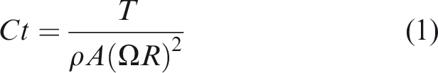
In equation (1), T is the thrust of the rotor, ρ is the air density, Ω is the rotational speed of the rotor, and A is the area of the rotor disk. 1
Wake interference visualization
In previous studies, it was expected that the rotor flow interaction affects rotor performance in uniform flow. In small multi-rotor UAVs in headwinds, the rotor interference appears to occur and affect the pitching moment. The flow around a quad-rotor UAV model was visualized using the smoke wire method in a wind tunnel to verify the flow interaction among rotors.
Method
The flow around a quad-rotor UAV in uniform flow was visualized using the smoke wire method. A wind tunnel in the experiment was open circuit. The dimensions of the tunnel’s test section were 900 × 900 mm. Smoke was generated from a heated wire across the test section. The quad-rotor UAV model diagonal axis distance between rotors was 450 mm. A top view of the model is shown in Figure 8. In subsequent sections, the same configuration was used. Rotor diameters were 239 mm, as shown in Figure 9, which is the same value used in a commercial multi-rotor UAV. The rotor was a Z-Blade propeller manufactured by DJI.

Dimensions of the quad-rotor model.

Rotor in the experiment.
The smoke wires spread vertically, passing the center of the left rotors heading towards the wind tunnel. The smoke wires were illuminated by white light sheets at the plane of the visualization. The set-up of the experimental model and tools are shown in Figures 10 and 11. The objective of the visualization is to examine the flow interference between the front and the rear rotors.
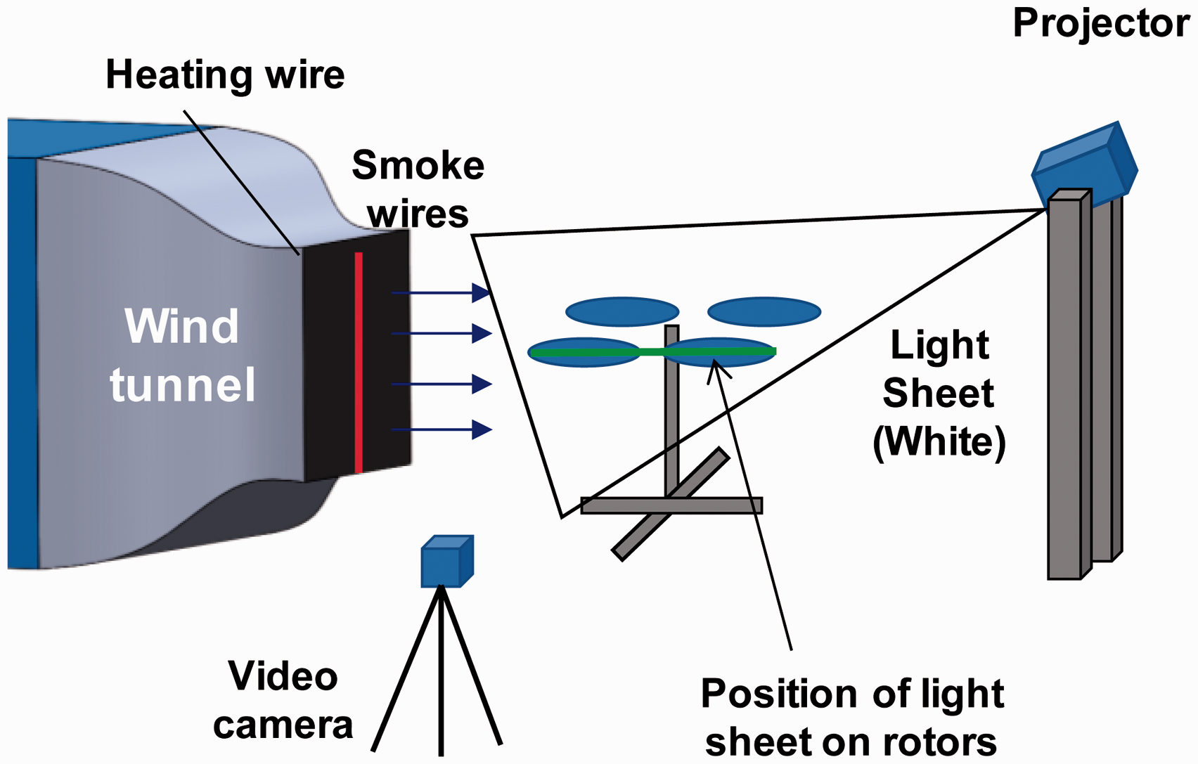
Experimental set-up for flow visualizations.

Wind tunnel and quad-rotor model.
The heating wire was vertically attached to the tunnel. The vertical plane of the light sheet was adjusted to pass the centers of the left side two rotors. The light sheet was generated from a projector with slits.
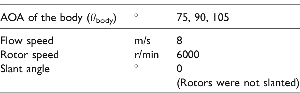
In the visualization, θbody was varied as 75, 90, and 105°. The rotors were not tilted. The flow speed was set to 8 m/s. The rotor speed was set to 6000 r/min. Table 1 lists the experimental conditions. A movie of the visualized flow was recorded using a digital video camera over 5 s. After the recording, a flow image was captured from the movie. Movies were taken from the left side of the model.
Experimental conditions of flow visualization.
Results
The visualized flows are shown in Figure 12. In Figure 12, the pictures are overlaid with a blue area, indicating the rotor and body positions. At AOAs of 75°, the flow passing each rotor was almost isolated. However, at AOAs of 90 and 105°, the rear rotor was at the back of the front rotor and the flow passing the rear rotors were affected by the front rotor wake. A comparison of the upper stream area of each rotor demonstrates that the area was larger in the front rotor than in the rear rotor at AOAs of 90 and 105°. The freestream flow in the rear rotor was bent by the front rotor.
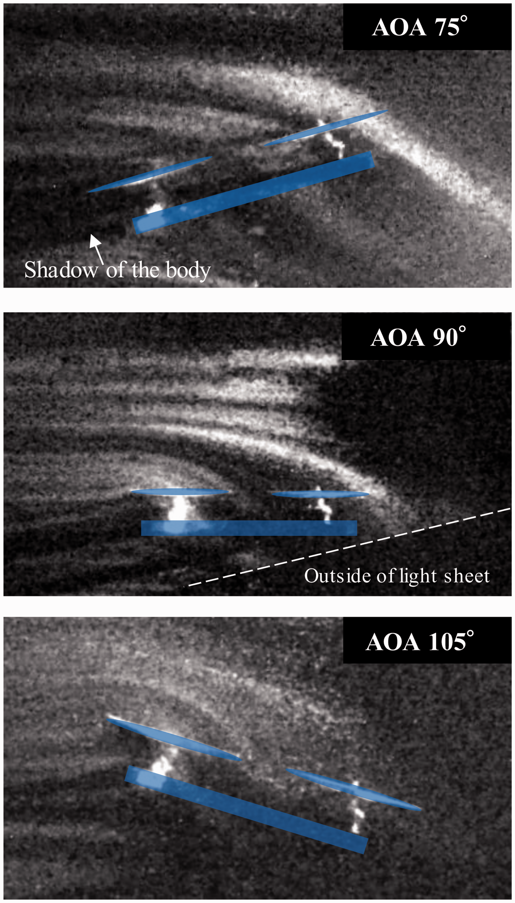
Visualized rotor flow interactions using light sheet and smoke wires.

Position of sensor and definition of rotor AOA.
Discussion
The visualization demonstrated that the stream passing the rear rotor was bent downwards above the front rotor at AOAs of 90 and 105°. An isolated rotor permits air to flow freely to the rotor in uniform flow. However, for plural rotor configurations, a front rotor prevents air from flowing in front of the rear rotor. When the front rotor is present, the rear rotor’s upstream is bent to downwards. This means there is an increase in the vertical flow speed passing the rear rotor compared with the isolated rotor. The increase in the vertical flow velocity results in thrust degradation of the rear rotor. Therefore, at AOA values greater than 90°, the rear rotor thrust performance appears to deteriorate compared with that of the front rotor. In contrast, the shape of the front rotor flow channel did not change and its performance was considered to be the same as in the isolated rotor performance. This thrust difference could result in a head-up pitching moment in uniform flow. At AOA of 75°, the rear rotors were higher than the front rotors. The effect of the front rotors appeared to be minimal compared with the effects at the other two angles. For the quad-rotor UAV in uniform flow, the flow channel of the rear rotors changed with varying θbody.
From the visualization, it could be concluded that the flow interaction affects the rear rotor performance at AOA values greater than 75°. This effect appeared to result in a thrust imbalance between the rotors and head-up pitching moment. This effect could be applied to generate pitching moment. With respect to the forward flight of the UAVs, the body tilted forward to generate thrust to move horizontally. Thus, θbody in forward flight was smaller than 90°. The effect of the rotor flow interaction on the pitching moment was considered to be small, as if the UAV tilted forward in uniform flow. However, the rotors were not completely isolated. The flow interaction between the rotors could generate head-up pitching moment in uniform flow at an AOA below 90°.
Pitching moment estimation based on isolated rotor thrust
The pitching moment reduction effect in the quad-rotor UAV in uniform flow by canted rotor configuration was estimated before conducting a wind tunnel test. The objective of the estimation is to determine the effect of the canted rotor configuration based only on the theory of changing rotor performance depending on the rotor AOA. The performance of an isolated rotor is measured in a wind tunnel. Based on the results, the pitching moment and thrust of the quad-rotor UAV by changing the θslant were estimated.
Isolated rotor test
Method
Measurements were conducted using a 1.01 × 1.01 m low-speed wind tunnel. The tunnel is a semi-closed circuit. The thrust and pitching moment were measured with a six-axis force and torque sensor attached to the basement of a brushless motor, as shown in Figures 13 and 14. The sensor is a SFS0017F100M0R5U6 force and torque sensor manufactured by Leptrino Ltd. The sensor is capable of measuring thrust from −10 up to 10 N, with a resolution of 1/100 N. Pitching moments could be measured from −0.5 up to 0.5 N·m, with a resolution of 1/2000 N·m. Sensor data were collected at 1200 Hz for 5000 times. The average value of captured data is used as the measured force to exclude noise generated by the rotor vibrations.

Set-up of isolated rotor force measurement.

Isolated rotor thrust in uniform flow vs. AOA.
The measurement conditions are listed in Table 2. Measurements were collected at a rotor speed of 6000 r/min. The rotor speed was controlled with an ESC, ESC32 developed in the Auto Quad project. The ESC controlled the rotor speed with a closed-loop control to within ±20 r/min of the target speed. The rotor speed was calibrated before the experiments using an AD-7152 optical tachometer manufactured by A and D. The brushless motor was an E310 manufactured by DJI. Forces were measured three times. However, for some conditions, as shown in Table 2, the measurement was performed once for each condition.
Experimental condition of isolated rotor test.

AOA: angles of attack.
Results
The thrust and pitching moment of the isolated rotor in uniform flow are shown in Figures 15 and 16. In Figure 15, the rotor thrust increases with an increase in AOA from 45 to 125°. In Figure 16, the pitching moment increases as the AOA increases from 45° to a peak angle. Once the angle is greater than the peak angle, the pitching moment decreases as the angle decreases.

Pitching moment of isolated rotor in uniform flow vs. AOA.
Discussion
The objective of this experiment was to determine the rotor performance at varying AOAs of the rotor for estimation of the slanted rotor configuration. From the results, we confirmed that the thrust and the pitching moment increased as the rotor AOA increased from 45° to each peak angle over 105°. In short, tilting a rotor forward decreased the pitching moment and thrust of the rotor in uniform flow. In addition, the peak angle of the pitching moment was greater than 90°. In forward flight, the UAV body is inclined forward to generate horizontal thrust. Thus, θbody is below 90°. When a rotor is tilted from −20 to 20°, each rotor angle range to wind was less than 110°. Therefore, rotor angles of a quad-rotor with canted rotor were smaller than the peak angle thrust. For pitching moment, although the rotor angle could exceed the peak angle, the peak pitching moment is almost identical at the angle of 120°.
In the measurement, the relationship between the pitching moment and the thrust of the rotor and the AOA was confirmed.
Estimation
Based on the isolated rotor test results, the effect of the canted rotor configuration on pitching moment reduction was estimated. The purpose of the estimation was to verify the behavior of the thrust and the pitching moment for a given AOA with canted rotors.
Estimation process
The headwind was set as 8 m/s. The rotor speed was set as 6000 r/min. To determine the thrust and the pitching moment at the AOA, we calculated an approximate square line for the thrust, and a line to the power of 4 for the pitching moment using the least squares approximation. The approximation lines are shown in Figures 17 and 18. The measured force is the result of the isolated rotor measurement.

Rotor thrust vs. AOA in uniform flow.

Rotor pitching moment vs. AOA in uniform flow.

Geometry of the quad-rotor UAV with slanted rotors.
The approximate lines are calculated as described below


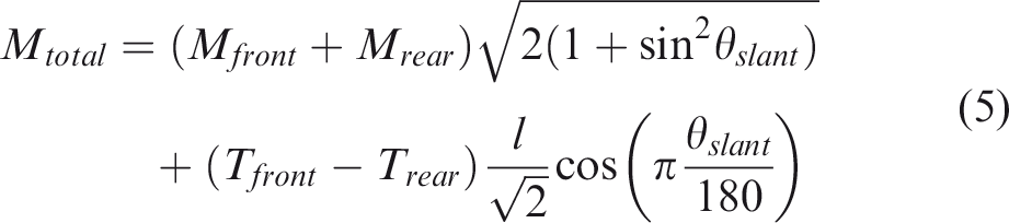
Using equations (2) and (3), the thrust and pitching moment of a quad-rotor UAV model with slanted rotors were estimated. The distance between the rotors in a diagonal axis for the model UAV (l) was 450 mm. The rotors slant radially from the center of the UAV; therefore, the force of the pitching moment was estimated with the consideration of slanting direction. The thrust and the pitching moment were calculated using the following equations

The model of the quad-rotor UAV used for the estimation is the same as the flow visualization model in Figure 8. The θbody was in the range 45–120°. The θslant were −20, −10, 0, 10, and 20°. If the θslant is positive, the rotors slant to the outside.
Estimated thrust and pitching moment
The estimated thrust is shown in Figure 20. The estimated pitching moment reduction compared with the pitching moment without rotor slanting is shown in Figure 21. Figures 22 and 23 show the pitching moment reduction resulting from a change in the rotor pitching moment in each rotor and differences in the thrust between the rotors. For the thrust shown in Figure 20, the thrusts at different slant angles are the same for each θbody. In Figure 21, the pitching moments are different in relation to θslant at the same θbody. For all five slant angles, the moment increased as the θbody increased from 45 to 90°. For a θbody of 105°, the moment increased as the rotor slants inside. For a θbody greater than 105°, the moment decreased. For a θbody greater than 105°, a θslant of −20° drastically reduced the pitching moment.

Estimated thrust difference of the quad-rotor model in uniform flow.

Estimated pitching moment difference of the quad-rotor model in uniform flow.

Estimated pitching moment difference generated by rotor pitching moment.

Estimated pitching moment difference generated by rotor thrust.
The curves of thrust vs. θbody were approximately linear from 45 to 120°, as shown in Figure 20. Thus, the opposite slanting of the front and rear rotors maintained the same total thrust. Similarly, the pitching moment of a single rotor vs. the θbody was approximately linear at a θbody of 90°. Thus, the total pitching moment generated from each rotor was approximately the same for each θbody, as shown in Figure 22.
Moreover, the difference in thrust between the front and rear rotors resulted in a difference in the pitching moment considering the θslant, as shown in Figure 23. When the θslant was positive and the rotors slant to the outside, the AOA of the front rotor was lower than that of the rear rotor. In this case, the rear rotor thrust was higher than the front rotor thrust. This difference decreased the head-up pitching moment.
The estimated results demonstrate that rotor tilting to the outside could reduce the moment in a headwind. At a θbody of 90°, and with a 20° outward rotor slant, the reduction in the pitching moment was estimated to be 0.24 N·m.
Quad-rotor model test
This section describes the wind tunnel experiments on a quad-rotor UAV model with slanted rotors in uniform flow. The objective of the experiment is to examine the effect of the canted rotor on pitching moment reduction and verification of the mechanism of the moment generation on the UAV in uniform flow by comparing the measured force with the estimated force, as presented in the previous section. In the measurements, we examined the thrust and the pitching moment of the body, that of each rotor, and the trim rotation speed of the rotors to cancel pitching moment.
Method
Thrust and pitching moment of the quad-rotor model
The low-speed wind tunnel is identical to the wind tunnel used in the isolated rotor measurement. Force was measured using a CFS034CA101 force and torque sensor manufactured by Leptrino Ltd. The sensor is capable of measuring thrust from −100 up to 100 N, with a resolution of 1/20 N. The sensor could measure pitching moment from −2 up to 2 N·m, with a resolution of 1/1000 N·m. The arrangement of the model and sensors in a test set-up is shown in Figure 24.

Experimental set-ups for quad-rotor UAV measurement. (a) The model and the wind tunnel and (b) Position of the model and the sensor.
Experimental conditions for the quad-rotor UAV model measurements.a

AOA: angles of attack; UAV: unmanned aerial vehicle.
aMeasurements were conducted three times.
bRotational speed was set to this value to maintain thrust at 90° for all slant angles, same value as thrust of non-slant rotors and maintain the same rotational speed for each slant angle.

Quad-rotor UAV model and a sensor position.
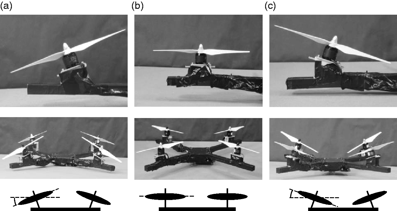
Quad-rotor UAV model at three slant angles. (a) θslant = 20°, (b) θslant = 0° and (c) θslant = −20°

Position of the force and torque sensor and the side view of the model.
Rotor thrust on the quad-rotor UAV model
Each rotor thrust on the model was measured to examine the thrust difference between the front and the rear rotors caused by rotor flow interference. The location of the force sensor, which is used in the isolated rotor measurement, is shown in Figure 27. Table 4 lists the experimental conditions of the measurements. The thrust was measured three times at each condition and averaged.
Experimental conditions of rotor thrust measurements.

AOA: angles of attack.
Trim rotation speed
Trimming rotor speed to cancel the pitching moment varying θbody was measured. The objective of the experiment was to examine the effect of the canted rotor configuration to the trimming of the rotor speed.
The experimental conditions are listed in Table 5. The UAV model generated the same thrust normal to the body with the reference rotational speed at each slant angle. The reference rotational speed is the average rotational speed between the front and rear rotors. The rotor speed was adjusted to cancel the pitching moment. The reference rotational speed was maintained at the same value. We recorded the rotor speed when the measured pitching moment was within ±0.03 to 0 N, which is smaller than 5% of the pitching moment of the model at 90°. The pitching moments were measured three times for each condition.
Experimental conditions of trim check measurements.

AOA: angles of attack.
aOnly in cases of slant angle 0°.
Results
Thrust and pitching moment
Figures 28 and 29 show the measured thrust and pitching moments of the model. In Figure 28, the thrust increases as the θbody increases for all the θslant. There was a difference in the thrusts within 2 N at θbody from 60 to 105° at the same θbody for different θslant. In Figure 29, the pitching moment increased as the θbody increased from 60 to 105°. The pitching moment decreased as the θbody increased from 105 to 120°. When θslant was −20°, the pitching moment decreased drastically for angles of attack greater than 105°. Comparing the pitching moment at the same θbody in relation to the θslant, the pitching moments with the rotors positively slanted were lower than those with negative θslant. This implies that rotors slanting outward reduce pitching moments. At θbody of 90°, the pitching moment of a 20° outward slanted rotor model was lower by 0.18 N·m compared with the model without slanted rotors. This represents a reduction of 26% of the pitching moment compared to a UAV without slanted rotors.

Thrust of the quad-rotor UAV model varying AOA at different slant angles and equal rotational speed for all rotors at the given slant angle.

Pitching moment of the quad-rotor UAV model varying AOA at different slant angles and equal rotational speed for all rotors at the given slant angle.
Rotor thrust on the quad-rotor model
Figure 30 shows the thrust coefficient of the front and rear rotors in the direction normal to the body. For θslant of 20 and −20°, the rotor direction was not normal to the body. To compare the thrust at different θslant, the normal Ct was used. Figure 31 shows the thrust of the rotors at given slant angles with raw thrust. The normal Ct was calculated using equation (6). Figure 32 shows the normal Ct difference between the front and rear rotors for different θslant.


Normal thrust coefficient of rotors in uniform flow.

Comparison of rotor thrust of the front and the rear rotors of the model for three slant angles. (a) 20°, (b) 0° and (c) −20°

Differences in the normal directional Ct for the three slant angles.
In Figure 30, the normal Ct of the front rotors increased as the θbody increased. The rate of increase of the normal Ct to the increase in the θbody was approximately the same for the three θslant. At the same θbody, the normal Ct was higher at small θslant. Thus, the normal Ct of front rotor at a θslant of −20° was highest out of the three θslant. At a θbody of 90°, the normal Ct of the front rotor at a θslant of −20° was higher than that of a θslant of 0° by 17%.
For the rear rotors, the normal Ct was approximately constant at varying θbody. At the same θbody, the normal Ct increased when the θslant increased. This implies that tilting the rear rotors to the outer side increased the rear rotor thrust. At a θbody of 90°, the normal Ct of the rear rotor at a θslant of 20° was higher than the value at 0° by 7.9%. However, the normal Ct of the rear rotor at a θslant of −20° was lower than the value at 0° by 18%.
With respect to the thrust of the rotors at different θslant, the thrust varies at varying θslant, as shown in Figure 31. At a θslant of 20° in Figure 31(a), the rotors were tilted to the outer side. For a given θslant, the normal Ct of the front rotor was smaller than that of the rear rotor at θbody below 97.5°. As θbody increases, the thrust of the front rotor becomes closer to that of the rear rotor. At a θslant of 0° in Figure 31(b), the rotors were parallel. The Ct values of both the rotors were the same at a θbody of 75°. As θbody increased, the front rotor Ct increased and the Ct difference between the rotors was extended. At a θbody of 105°, the normal Ct of the front rotor was higher than that of the rear rotor by 36%. At a θslant of −20° in Figure 31(c), the rotors were tilted to the inner side. As θbody increased, the normal Ct of the front rotor increased. The normal Ct of the front rotor was higher than that of the rear rotor in the range of θbody. At a θbody of 90°, the normal Ct of the front rotor was larger than that of the rear rotor by 60% at a θslant of −20°.
Figure 32 shows the normal Ct difference between the rotors at different θslant for varying θbody. The difference increased as the θbody increased for the three θslant. The difference at a θslant of 20° was the lowest out of the three θslant within the measured range of the θbody. By contrast, the normal Ct difference at a θslant of −20° was the highest out of the θslant. For a θslant of 20°, the difference was negative in the range of the θbody, which means that the head-down pitching moment was generated. At a θslant of 0°, the normal Ct difference was close to 0 at the θbody of 75°. At θbody of 0°, the value at a θslant of 20° was lower than that at a θslant of 0°. The normal Ct difference for a θslant of −20° was larger than the value for a θslant of 0°.
Based on each rotor thrust measurement, the effect of the rotor flow interference between front and rear rotors on pitching moment generation was examined.
Trim rotational speed
Figure 33 shows the trimming rotor speed of the rotors at θslant of 20, 0, and −20°. The reference rotational speed was different in each θslant to maintain the same rotor thrust. The reference rotor speed is the median value of the front and rear rotor speeds. The reference rotor speeds for θslant of 20 and −20° were higher than the value at a θslant of 0° by 200 r/min. Therefore, a comparison with the raw trim rotor speed is not appropriate.

Rotor speed ratio to the reference rotational speed to cancel pitching moment.
For tendency of the trim comparison with the rotational speed from the reference rotor speed, the rotor speed difference between the rotors to cancel the pitching moment decreased as the rotor tilts to the outer side. The trim of the rotor speed decreased as θbody decreased below 105°.
Discussion
Thrust and pitching moment of a quad-rotor UAV model
The estimated pitching moments for each slant angle based on the experimental results of the moment without slanting are shown in Figure 34. Figure 34 contains measured pitching moments for a comparison of the experimental results with the estimated results.

Comparison of measured pitching moment of the quad-rotor UAV model in uniform flow with estimated results.
As shown in Figure 28, although the rotational speeds were fixed to maintain constant thrust at 90° for each θslant, the thrusts differ within 2 N at the same θbody. The difference was significant at negative θslant. We assumed that flow interaction between the rotor slipstream and the body frames could cause this difference in thrust.
The peak angle of the pitching moment was approximately 105°. In addition, the pitching moment increased as θbody increases, and increasing θslant reduces the pitching moment, as estimated. Thus, we confirmed that a rotor tilting to the outside could reduce the total pitching moment. The trend of the pitching moment for θbody less than 105° was similar to the estimated result, as shown in Figure 21. However, the pitching moment difference between the measured and estimated increased as θslant increased. When θslant increased, the estimated pitching moments were comparable to results at θslant of 10 and −10°. The estimated pitching moment at a θslant of 20° was lower than that of measured value. The effect of pitching moment reduction was smaller compared with the estimated values for θslant greater than 10°. At θbody of −20°, the pitching moment was underestimated compared with the measured value. At θbody higher than 105°, the pitching moment reduction differs from that of the estimated in most of the θslant. In the case where θbody is higher than 90°, each rotor angle could be higher than 110°. Therefore, the rotors appear to stall at high θbody, which could make it difficult to estimate the exact pitching moment.
Although, each rotor performance at θbody higher than 105° was difficult to estimate from the isolated rotor experimental results in the high rotor AOAs, we verified that the difference in the reduction in the pitching moment as θbody increased was approximately constant for each θslant.
In the measurements, the pitching moment reduction with the rotor slanting outwards was confirmed. The reduction by slanting was close to the estimation. To apply slant rotors to quad-rotor UAVs, verifying the effect of rotor slanting on yawing moment control is required. In addition, for rotor speed between the front and rear rotors to cancel, it is anticipated that the pitching moment will be changed by slanting.
Rotor thrust on the quad-rotor UAV model
Rotor thrust measurement results demonstrate that the front rotor thrust in uniform flow increased when θbody increased. However, the rear rotor thrust was approximately constant with varying θbody in the range of 75–105°. In isolated rotor measurements, we confirmed that the rotor thrust increased as the AOA of the rotor increased. Therefore, the relationship between the rear rotor thrust and the rotor angle is different from isolated rotor thrust.
Differences in thrust variation between the rotors without tilting appear to be due to rotor flow interaction, as mentioned in the flow visualization. It was presumed that the flow channel of the rear rotor changed at the downwind side of the front rotor. At a θbody of 75° without rotor tilting, the upwind side of the rear rotor was clear. Therefore, the effect of the rotor flow interaction was small at a θbody of 75°. In contrast, thrusts of the rotors differ at θbody of 90 and 105°. Measured results agree with the interference on rotor thrust differences between the rotors.
In summary, for each rotor measurement, the θslant changed the thrust of the rotors. At positive tilt angles, the front rotor thrust decreased and the rear rotor thrust increased compared with normal parallel rotor configuration. Owing to the decreasing rotor thrust difference, the pitching moment was degraded. Furthermore, θbody affects the rotor flow interactions and generates a pitching moment at θbody above 75°. Results of the difference of the normal Ct agree with the theory. The theory identified the mechanism of the pitching moment reduction in uniform flow.
Trim of rotor speed to cancel pitching moment
To compare the trim rotational speed, changes in the rotor speed compared with each reference rotor speed is shown in Figure 35. The trend of the rear rotor speed changing θbody at each θslant appears to be similar. As θbody increased from 60 to 105°, the rear rotor speed increased. For θbody greater than 105°, the rotational speed increased as θbody increased. In contrast to rear rotor speed, the front rotor speed decreased as θbody increased until 105°. Above 105°, the front rotor speed increased as θbody increased.

Trimming rotor speed difference ratio between front and rear rotors at different slant angles.
The difference in the rotational speed between the rotors depends on θslant. In Figure 35, rotor tilting to the outside decreased the trim speed. The trim rotational speed at θslant of 20° was the lowest in the three θslant. At the same θslant, the trim rotational speed difference decreased as the θbody decreased. At a θslant of 90° without rotor tilting, the trimmed rotational speed difference was 40% of the reference rotor speed.
The effect of θslant on the trim rotor speed was confirmed through measurements. The trim rotational speed decreased as the θbody decreased below a θbody of 105°. Therefore, in headwind flight, the rotor trim appears to decrease by inclining the body to the upwind side because a multi-rotor UAV inclines its body into this side to generate thrust to move forward.
The experiment verified that rotor tilting to the outer side reduced the trim rotor speed. At a θbody of 90°, a θslant of 20° reduced the trim rotational speed by 16% compared with the parallel rotor configuration.
Affecting factors on pitching moment generation on quad-rotor UAVs
In the previous estimation process, only the pitching moment difference from that of the parallel rotor configuration due to rotor tilting at varying θslant was estimated, but not the total pitching moment. This is because we concentrated on the effect of the rotor tilting and could not consider the effect of the body drag and rotor flow interactions without a measurement. In the wind tunnel experiment, rotor thrust measurements verified the effect of rotor flow interference and body drag. Based on the experimental results, the total pitching moment generation was estimated. This estimation focused on validating the estimation results and verifying the ratio of the pitching moment generation factors.
The pitching moment appears to be generated from three factors as described. The factors are the thrust difference between the rotors, pitching moment of rotors, and drag force to the body. Thrust difference appears to be caused by rotor flow interactions and rotor tilting. Therefore, pitching moment generation from a thrust difference is divided into the two factors.
The estimation was performed as described below. The UAV configuration used in the estimation was the same as the previous estimation. The pitching moment and rotor thrust of each rotor were estimated using equations (2) and (3), which exclude the effect of rotor flow interactions. The effect of rotor flow interactions was estimated from the measured thrust difference in a measurement of the rotor thrust on the quad-rotor UAV model. In the estimation process, the rotor thrusts of the parallel configuration were used because those of the rotor tilting case contained other effects, such as rotor radial tilting. The approximated Ct difference between the rotors to the AOA of the rotor is described in equation (7).


The pitching moment generated from the rotor interference was estimated using equation (8).

This approximate line could be applied to the AOA from 75 to 105°. The pitching moment generated from the drag force on the body was measured in the wind tunnel experiment. The approximate line of the pitching moment to AOA was derived using equation (9).
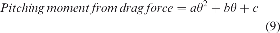


The total pitching moment from the factors was estimated using equation (10).

Myb: pitching moment from the total of each rotor pitching moment.
Myc: pitching moment from rotor thrust difference caused by rotor flow interaction.
Myd: pitching moment from rotor thrust difference caused by rotor tilting.
Figure 36 shows a comparison of the estimated and measured pitching moments of the quad-rotor UAV model in uniform flow. Figure 37 shows the pitching moment generated from each factor for the parallel configuration, without rotor tilting. At a θslant of 0°, Myd is 0.

Pitching moment estimation in uniform flow for varying slant angles.

Proportion of estimated pitching moment generated from each factor without rotors tilting.
The estimation line of the total pitching moment at a θslant of 0° was close to the measured results in the wind tunnel at a θbody of 82.5 and 90°, as shown in Figure 36. However, the estimation line was different from the measured pitching moment at 75, 97.5, and 105°. At a θbody of 75°, the estimated pitching moment was lower than the measured value by 0.11 N·m. At a θbody of 105°, the estimated pitching moment was larger than the measured pitching moment by 0.09 N·m. With respect to the rotor tilting angle to the outer side, the pitching moment was underestimated compared with the measured moment. At θslant different from 0°, the estimated pitching moment was underestimated. However, for θslant of −10, 0, and 10°, the estimated total pitching moment was close to the experimental results.
The pitching moment difference between the estimated and the measured results at θslant of 20 and −20° could be caused by inadequate treatment of the rotor direction in the pitching moment estimation process. Rotors of quad-rotor UAVs were tilted in the radial direction. However, we ignored the rotor moments generated in the yawing and rolling direction of each rotor, only in the estimation of the moment, to use a simple model. Although the rotor thrust was considered with the tilting in the yawing direction, the pitching moment of the UAV body was not considered with rotor moments generated in the two axes. For a precise estimation, the moment generation when the rotor tilts in the radial direction should be considered appropriately. Nevertheless, for a small θslant, this estimation model could estimate the effect of rotor tilting.
In Figure 37, the pitching moment generated from the drag, and rotor pitching moment increased slightly as θbody increased. The rotor pitching moment from each rotor moment had the largest ratio of the moment generation in the three factors. The moment generated from rotor flow interferences increased as θbody increased. Out of the three factors, the degree of increase of the pitching moment slope was steepest. At a θbody of 90°, the contributions of the pitching moment generation factors were 54% by the rotor pitching moment, 23% by the rotor flow interaction, and 23% by drag force. When the rotor tilted to the outer side, the moment is subtracted from this estimation line in the parallel configuration.
By considering the factors of the pitching moment generation, we identified the effectiveness of each factor. Additionally, we can explain the effect of rotor tilting compared with the pitching moment generation factors.
Conclusions
To reduce the pitching moment of the quad-rotor UAV in uniform flow, a canted rotor configuration was proposed. In this study, rotor flow interaction between the front and rear rotors was visualized using the smoke wire method to verify the occurrence of the flow interaction. The pitching moment reduction of a quad-rotor UAV in uniform flow by canted rotors was estimated based on isolated rotor performance. In the wind tunnel experiments, the effect of the pitching moment by a canted rotor was investigated using the quad-rotor model. Furthermore, the mechanism of the pitching moment generation in wind was examined based on measured force and visualization results.
Visualization results suggested that front rotor flow interfered with rear rotor flow at AOAs of 90 and 105°. However, flow interaction was not observed at an AOA of 75°.
The thrust and the moment of an isolated rotor in 8 m/s uniform flow were measured for the estimation of pitching moment reduction by slanted rotors. The effect of rotor tilting by 20° to the outer side was estimated to reduce the pitching moment by 0.24 N·m at an AOA of 90° compared with the UAV with parallel rotors.
In the wind tunnel measurements, the relationship between the pitching moment and the angle of the body for five rotor tilt angles was confirmed. It was verified in the experiment that rotor tilting by 20° to the outer side degrades the moment by 0.18 N·m, which was 26% of the moment for a quad-rotor UAV with parallel rotors at an AOA of 90°. Although the estimated and experimental results of moment generation differ at a tilting angle of 20 or −20°, the effect of the canted rotor was established. Additionally, rotor thrust measurements on the quad-rotor UAV model verified moment generation due to rotor flow interaction. The contribution of the effect of the rotor flow interaction to pitching moment generation was estimated to be approximately 23% at a body AOA of 90° without rotor tilting. Furthermore, the reduction in trim rotational speed difference to cancel pitching moment with the rotor tilted to the outer side was verified.
Based on the experimental results, we conclude that rotor tilting to the outer side reduces pitching moment generation. Further studies are required to apply the concept to multi-rotor UAVs because the effect of rotor tilting on mobility is unclear.
Footnotes
Acknowledgements
We thank to staff of the wind tunnel facility and students from our laboratory: Jun Ashizawa, Kaede Yakushigawa, Taiki Kunishio, and Masayoshi Kohno.
Declaration of conflicting interests
The author(s) declared no potential conflicts of interest with respect to the research, authorship, and/or publication of this article.
Funding
The author(s) disclosed receipt of the following financial support for the research, authorship and/or publication of this article: This work was supported by the Grant-in-Aid for JSPS Research Fellow Grant Number 16J02686.