
Abstract
In this paper, we present the design and implementation of two nonlinear observers: nonlinear extended state observer and sliding mode observer for estimating the pitch, yaw and roll angles and angular rates of a fixed-wing unmanned aerial vehicles system under a decoupled-reduced model in real flight experiments. A backstepping control law is designed for control in a decentralized way for altitude, yaw and roll of the airplane. This scheme allows us to test experimentally the feasibility of using the online estimated data from the observers in flight control, which is useful for increasing the robustness of the control and the safety of flight. Furthermore, a comparative analysis of the performance of both nonlinear observers is conducted.
Keywords
Introduction
A large number of applications on fixed-wing unmanned aerial vehicles (UAV) have been raised during the last 15–20 years. Fixed-wing UAV allow to perform complex tasks such as monitoring disaster areas, localization of victims, infrastructure inspection for inaccessible locations, surveillance tasks and photography. 1 Nevertheless, aerial systems, similarly to other mobile devices, are subject to suffer from failures or inaccuracy on sensors. Moreover, navigation and control systems malfunctioning due to sensor failures on flying machines can result in severe damage or in the destruction of the device. Several approaches have been proposed to prevent loss or degradation of signals of the states which are used in the control and navigation systems.
A recent approach to address attitude estimation of UAV or other mobile systems is the use of nonlinear observers. 2 In addition, Fusini et al. 2 and later Grip et al. 3 propose a nonlinear observer for position, velocity, acceleration, attitude and gyro bias of a UAV. Data are provided by an IMU, Global Navigation Satellite System (GNSS), as well from video camera and machine vision systems. These works are further improved in Hosen et al. 4 by using a new approach for calculating the velocity of a UAV based on optical flow and epipolar geometry. Experimental results obtained with a fixed-wing UAV are presented in the literature.3,4 In Byrne et al., 5 nonlinear observers with time-varying gains are integrated with high-performance sensor fusion based on GNSS and IMU for navigation of a vessel. Simulation results are presented.
On the other hand, other approaches from nonlinear systems theory for designing nonlinear observers are the sliding mode observers (SMO) and the nonlinear extended state observer (NESO). The SMO design shows great potential by offering advantages similar to those of sliding mode controllers. Some of these advantages include an inherent robustness to parametric uncertainty, easiness of implementation in certain nonlinear systems and, contrary to the case of controller design, the chattering issues in the sliding-mode observer design are only linked to numerical implementation. 6 There are some previous works on SMO related to the present contribution. In Tan and Edwards, 7 a method for designing sliding mode observers for detection and reconstruction of actuator and sensor faults is described. The work in Xu et al. 8 reports the design of a SMO in order to estimate the angle of attack and the flight-path angle for a hypersonic flight vehicle. A backstepping control design, running in parallel with a sliding mode observer, implemented for a quadrotor UAV is presented in Madani and Benallegue. 9 In the work of Yana and Edwards, 10 an SMO for actuator fault detection and an isolation scheme for a class of nonlinear systems with uncertainty are presented. In the sensor-faults area, the application of a robust method for fault reconstruction using a sliding-mode observer is considered in Alwi and Edwards. 11 Regarding the application of the SMO to time-delay systems, in Yan et al. 12 is proposed a robust sliding-mode observer for nonlinear time delay systems to estimate the system state and the unknown parameters simultaneously by using an adaptive law. The proposed scheme is tested by simulations of a bioreactor system. It is worth to mention, however, that the aforementioned works on SMO show only simulations.
In contrast with SMO, the nonlinear extended state observer is independent of the mathematical model of the system. This fact, in principle, makes NESO more robust than SMO. Some applications of this observer in motion control and industrial control are reported in literature.13,14
Some developments of this kind of observer used in UAV control have been reported, for example in Yuan et al., 15 where an extended state observer is used to estimate and compensate unmodeled dynamics in the presence of external disturbances. In order to cancel out the effects of uncertainties in the form of unmodeled dynamics or external disturbances, an extended state observer compensator is designed in Qiu et al. 16 to enhance the robustness of an aircraft flight control system. A practical example of estimation and compensation of unknown disturbances associated with a particular dynamical system using extended state observer design is presented in Fang et al. 17 Based on an extended state observer, in Zhao et al. 18 it is proposed an output-feedback control strategy for the attitude control of a quadrotor aerial vehicle. Similarly to the SMO applications mentioned early, the aforementioned work related to NESO report only simulations. A relevant application of extended state observers to estimate uncertainties in a control scheme for a rolling aerial vehicle (RAV) is presented in Chen et al. 19 In that work, extended state observers are used to estimate the uncertainties of the RAV. In addition, an ESO-based sliding mode controller is synthesized for the angular rate loop. In Parada et al., 20 simulations of the SMO and NESO for pitch, yaw and roll angles and angular rates estimation on a fixed-wing UAV platform are presented. The nonlinear observers were tested online and the estimated values were used in the control loops for altitude, yaw and roll, by using a PD control law. However, experimental results are presented only for the SMO case.
Hence, in order to investigate the feasibility and convenience of implementing these nonlinear observers in UAVs for estimation of the states of the system, in this paper we present the implementation of two nonlinear observers, SMO and NESO, for estimating the pitch, yaw and roll angles and angular rates of a fixed-wing UAV system in real flight experiments. The online implementation of both nonlinear observers allows us to use the estimated states in the respective control loop for altitude, yaw and roll. The control law implemented in each of these control loops is designed by the well-known backstepping approach. This scheme allows us to test experimentally the feasibility of using the online estimated data in flight control, which is useful for increasing the robustness of the control and the safety of flight. Furthermore, a comparative analysis of the performance of both nonlinear observers is conducted. The main objectives of this work are, first, to demonstrate practically that the estimation errors related to the estimated states from the observers converge to zero after a period of time. Second, to prove flight stability of the aircraft when the states estimated online by the observers are fed to the control loop. This kind of stability means achieving motion stability in roll, pitch and yaw. Third, to illustrate some differences in the experimental results between each nonlinear observer implementation, SMO and NESO. These objectives are achieved using a decoupled-reduced model of a UAV. One contribution of the work is to provide an experimental comparison of the utilization of two of the most successfully applied observers, SMO and NESO, to a general linear system, which under some assumptions has the adequate structure to represent three movements of the fixed-wing UAV.
The remainder of the paper is structured as follows: In the next section, the model of the fixed-wing UAV is presented. Next, the design of the nonlinear observers is developed, followed by the design of the proposed backstepping controller. Then the experimental platform as well as the real-time flight experiments is described, and the corresponding results are presented and discussed. Finally, some conclusions are given.
Model of the fixed-wing UAV
In this section, we present the model of a fixed-wing UAV used in this work. First, we will establish some useful assumptions, as were considered by Stevens and Lewis
21
to propose the so-called decoupled-reduced aircraft model.
The fixed-wing UAV can be considered as a rigid body by omitting its flexible structure.
The curvature of the earth’s surface can be neglected when considering short distance flights.
Assumption 1
Assumption 2
Based on these assumptions, it is shown in Stevens and Lewis 21 that the equations of motion of the airplane can be linearized about a nominal flight path. Furthermore, when this flight lies in the plane of symmetry of the unperturbed vehicle, the linearized equations form two independent sets, the longitudinal dynamics and the lateral dynamics.
Longitudinal dynamics
The parameters involved in the longitudinal dynamic model are shown in Figure 1. These parameters allow to analyze the movement toward the front of the airplane, which is specially useful for altitude control.
22
The longitudinal part of the model of the airplane is governed by the following decoupled kinematic and moment equations
Pure pitching motion. Lateral view of the airplane.


Lateral dynamics
The lateral dynamics of the airplane generates a roll motion and induces a yaw motion (the other way around). Hence, there exists a natural coupling between the rotations about the axes of roll and yaw as is reported in Mclean.
23
However, without loss of generality, we assume in this contribution that yaw and roll movements are decoupled on the airplane dynamics. This is established in the following:
Yaw and roll movements of the airplane model can be considered as decoupled.
24
Assumption 3
This assumption allows us consider that yaw and roll movements can be controlled independently from each other. Another necessary assumption for this study is the following:
The effects of the engine thrust in the airplane dynamics can be neglected.
23
Assumption 4
In Figure 2, the yaw motion is represented, which is described by the following kinematic and moment equations
Pure yawing motion. Superior view of the airplane. Pure rolling motion. Back view of the airplane.


It is convenient for this analysis to define a general structure of the decoupled reduced model from equations (2) to (7) as


Design of nonlinear observers
For the design of the nonlinear observers, let us consider the general decoupled-reduced dynamic model (equations (8) and (9)) that represents the dynamics of the pitch, yaw, and roll motions.
The control problem addressed in this work is to estimate the entire state vector
The design of the nonlinear observers will be performed individually for the dynamics of each movement: pitch, yaw and roll.
Sliding mode observer
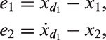
Let us define the estimation error as


Let us define the dynamic system of the estimation error as
Let consider the estimation error system (equations (
12
) and (
13
)) obtained from the observer (equations (
10
) and (
11
)) and the decoupled-reduced model (equations (
8
) and (
9
)), where α1 and α2 are positive constants. The coefficient c of the decoupled-reduced model satisfies
We propose a candidate Lyapunov function as follows:
Proposition 1
Proof


Note that the first term of equation (18) is negative definite if both α1 and α2 are positive. The second term is negative if

To ensure that the coefficient

This bound is negative definite if
The sliding-mode observer for pitch movement is obtained by substituting equations (1) and (2) in equations (10) and (11)


Similarly, the SMO for yaw movement is defined with equations (10) and (11) and equations (4) and (5) as follows


Last, the SMO for roll movement is obtained with equations (10) and (11) and equations (6) and (7) resulting in


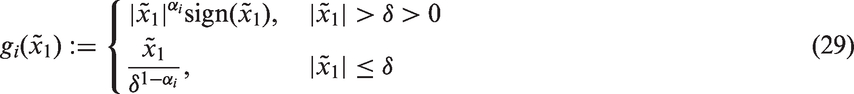
Nonlinear extended state observer
In Han,
29
it is proposed a nonlinear extended state observer in the form


In this work, inspired on the work by Han,
29
NESO design for pitch movement is defined by substituting equations (1) and (2) in equations (26) to (28), which yields


Similarly, NESO is designed for yaw movement as a result of combination of equations (26) to (28) and equations (4) and (5) as


Last, the NESO for roll movement is defined by the combination of equations (26) to (28) and equations (6) and (7) as


Design of the backstepping controller
In order to test and to analyze the performance of the closed-loop system by using the two observers (SMO and NESO), we designed a backstepping control law, to be implemented in three decoupled control loops, one for each specific movement, pitch, yaw and roll. Given the dynamical system (equations (8) and (9)), the tracking errors are


We can assume that


According to the Backstepping control design technique,
32
we propose a first positive definite Lyapunov candidate function as

Taking the temporal derivative of equation (41)


We assign e2 as a virtual control input


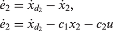
We introduce a new dynamics of the form


Substituting equation (47) in equation (46) yields

Now we propose a second Lyapunov candidate function

Taking the temporal derivative of equation (49) along the trajectories of equations (45) and (48)

We propose the control law as


The control law (51) can be rewritten as
Since x1 and x2 can represent any of the angles
Since this controller is designed for the generalized form of the dynamics of the airplane (equations (
8
) and (
9
)), it can be applied for the particular dynamic decoupled-reduced models of pitch (equations (
1
) and (
2
)), yaw (equations (
4
) and (
5
)) and roll (equations (
6
) and (
7
)) and it conservates its stability properties.
Remark 1
Remark 2

Experimental results
This section presents the fixed-wing UAV system and the obtained experimental results.
Embedded system and experimental setup
Figure 4 shows a block diagram of the embedded system. The embedded system consists of a microprocessor Rabbit RCM6000, which reads the data from an Inertial Measurement Unit (IMU) and communicates with the radio control set. The radio control Futaba T7C (transmitter and receiver) is used to pilot the plane and to set the autopilot commands. The IMU is the Microbotics MIDG SERIES INS/GPS, which supplies the pitch, yaw, and roll angles (Euler angles) as well as the respective angular rates. The observer and control algorithms were run on the microprocessor Rabbit, with a clock time of 1 ms. These algorithms were programmed in DynamicC language. The integration algorithm used was the Euler algorithm. The altitude data are supplied by an altimeter together with a microcontroller Parallax. We have also used XBee-PRO 802.15.4 wireless module in order to transmit to a fixed base the needed signals for computing and displaying the control signals.
Block diagram of embedded system.
During the tests, the data provided by the IMU (i.e. Euler angles) are used in the estimation algorithms. In addition, it provides the respective angular rates only for comparison with the observed states. Moreover, the observed states are used in the control loops for each controlled variable, i.e. pitch, yaw and roll, using the backstepping control law. The experimental platform with the embedded system is shown in Figure 5.
Embedded system on the experimental platform.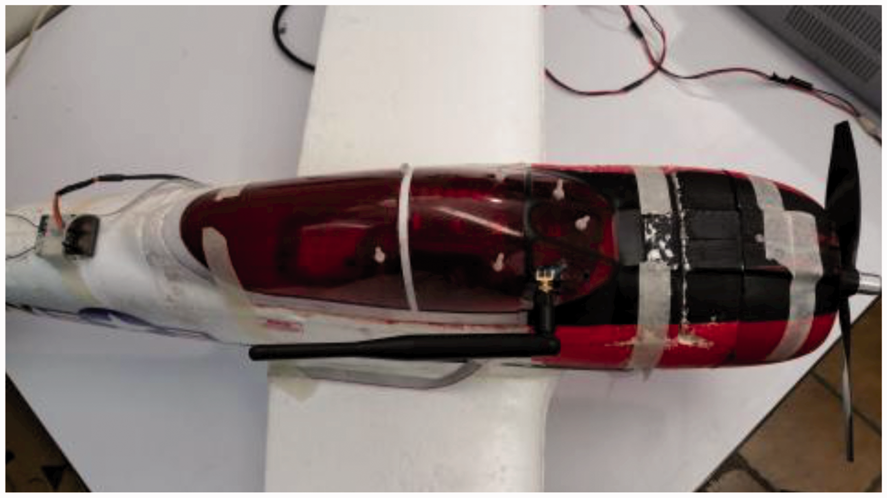
We conducted experimental tests of three movements: control of altitude, yaw, and roll. Altitude control is performed indirectly by controlling pitch angle. Yaw control and roll control are performed directly. For each movement, the tests were implemented in two flights. In the first flight of each movement, the sliding mode observers were implemented for control of the respective movements, and in the second flight of each movement, the nonlinear extended state observers were implemented. The reason is because a key condition of the tests is that the estimated signals are used in the real-time control loops of each movement. However, we were careful in conducting the tests under very similar environmental conditions.
Experimental parameters of the gains of the control law and the aerodynamic coefficients.

The table also shows the aerodynamic coefficients of the airplane, which were obtained experimentally.
Experimental parameters for the SMO.

SMO: sliding mode observer.
Experimental parameters for the NESO.

NESO: nonlinear extended state observer.
Computation of quadratic norm
The quadratic norm of the error is defined by

Experimental tests for altitude movement
The objective of the experimental test for altitude movement consists of keeping the fixed-wing UAV at a desired height (hd).
Experimental results with the SMO
Figure 6 shows the desired height (hd) and the measured height (h). Figure 7 shows the measured and the estimated pitch angles. Note that both signals, estimated and measured, seem to overlap.
Altitude movement behavior when applying a backstepping control law with the sliding mode observer. Estimated and measured pitch angle with the sliding mode observer, with 

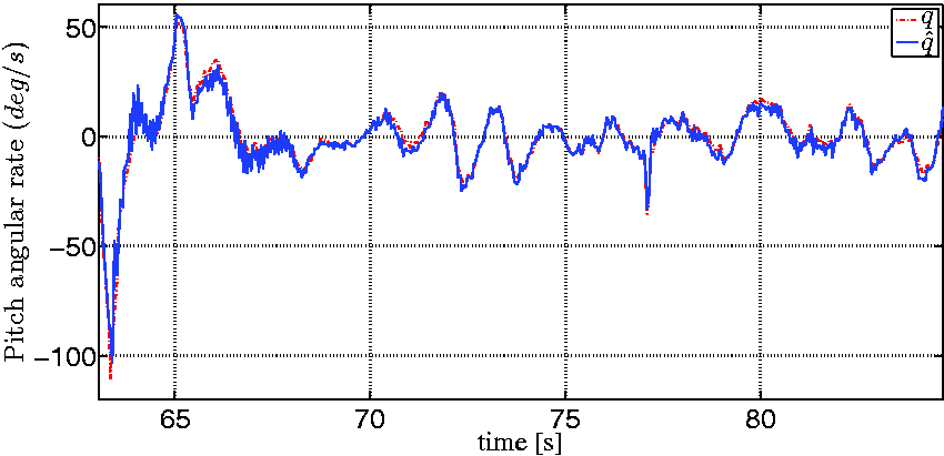
Figure 8 shows the measured and the estimated pitch rates. Note that also in this figure both signals seem to overlap, which indicates a very small estimation error. The quadratic norm of the estimation error is Estimated pitch rate with the sliding mode observer, with 
Experimental results with the NESO
Figure 9 shows the desired height (hd) and the measured height (h). Figure 10 shows the experimental results for the estimated pitch angle. The measured and the estimated pitch rate is shown in Figure 11. Note that in both Figures 10 and 11, signals seem to overlap. The computed quadratic norms of the estimated errors are Altitude motion behavior when applying a backstepping control law with the nonlinear extended state observer. Estimated pitch angle with the nonlinear extended state observer, with Estimated pitch rate with the nonlinear extended state observer, with 

Experimental yaw movement
For this movement, the reference angle (ψd) is fixed at a certain value during the flight of the fixed-wing UAV, and the controller must maintain such a reference.
Experimental results with the SMO
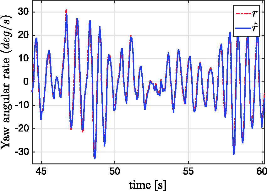
The measured ψ and the estimated Estimated yaw angle with the sliding mode observer, with Estimated yaw rate with the sliding mode observer, with 
Experimental results with the NESO
In Figure 14, we can observe the behavior of the measured ψ and the estimated Estimated yaw angle with the nonlinear extended state observer, with Estimated yaw rate with the nonlinear extended state observer, with 

In general, we can observe that the states estimated by the observers are very similar to the provided by the sensors.
Experimental roll movement
For this movement, the desired roll angle is fixed at zero degrees (
Experimental results with the SMO
Figure 16 shows the measured φ and estimated φ roll angle for this experiment. Figure 17 shows the measured p and the estimated Estimated roll angle with the sliding mode observer, with Estimated roll rate with the sliding mode observer, with 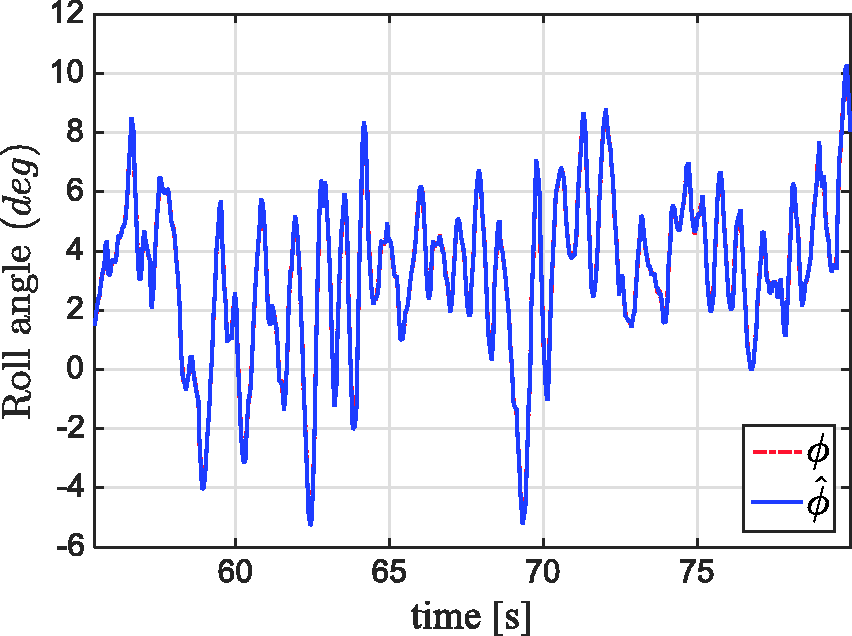

Experimental results with the NESO
In Figure 18, we can observe the measured φ and the estimated Estimated roll angle with the nonlinear extended state observer, with Estimated roll rate with the nonlinear extended state observer, with 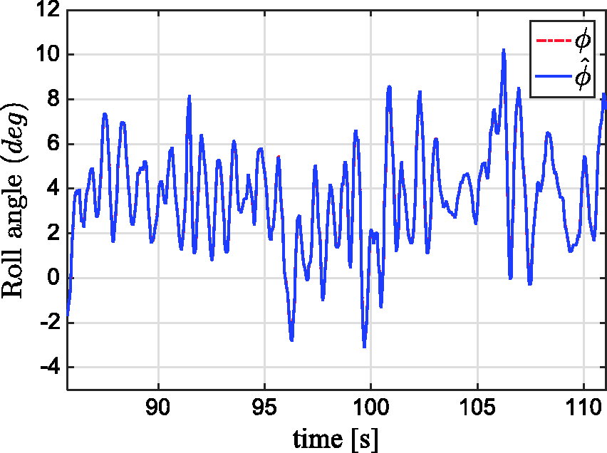

Results from both observers show that the estimated signals are very similar to the measured ones. The behavior of the airplane shows the stability of movement, as expected when the control loops are fed with the signals of the observed states. Furthermore, results from each nonlinear observer are very similar between them. Nevertheless, it is remarkable that the NESO produced very good results taking into account that it does not depend on the model of the plant, in contrast to the SMO.
Conclusions and future work
We have presented the design of two types of nonlinear observers for estimating the states of the model of a fixed-wing UAV, the SMO and the NESO. We presented results of real-time flight experiments of the implementation of both observers for estimating pitch, yaw and roll angles and angular rates. In addition, the design of a backstepping controller for altitude, yaw and roll is reported.
The convergence of the states estimated by the observers was demonstrated experimentally. In addition, it was observed that pitch, yaw and roll movements were stable when the on-line estimated states are used in the control loop. We also have shown the results of the implementation of both observers in terms of the quadratic error of the estimated states. Both observers produce very small values of the quadratic errors, and although significant differences cannot be observed in the results, it is remarkable that the NESO exhibits more robustness since it does not depend on the model. Moreover, for the SMO designed, we have demonstrated a result on the global asymptotic stability of the estimation error system. Future contributions will focus on investigating the performance of other robust controllers for fixed-wing UAVs, together with nonlinear observers, to address the problem of sensor failures on these UAVs.
Footnotes
Declaration of conflicting interests
The author(s) declared no potential conflicts of interest with respect to the research, authorship, and/or publication of this article.
Funding
The author(s) received no financial support for the research, authorship, and/or publication of this article.