
Abstract
The dynamics of an axisymmetrical swirling jet is studied via global linear stability and resolvent analyses. The modeled flow represents a combustor-like swirling jet, that is turbulent, compressible, non-parallel, and enclosed. In particular, the computational domain embeds a realistic axisymmetrical swirler model to resolve the mode conversion process. Swirl fluctuations are non-negligible on this configuration representative of a swirl burner, and match the analytical mode shapes of inertial waves of an inviscid uniform flow as obtained from global stability analysis. The stability map presents two eigenvalues driving a modal amplification. These eigenmodes couple a standing acoustic wave sustained in the mixing duct and the combustion chamber with the Kelvin-Helmholtz mechanism at the mixing duct exit and the acoustic-vorticity mode conversion process at the swirler, and act as a frequency selection criterion. Finally, the most amplified forcing from the resolvent analysis is similar to an unsteady heat source in the combustion chamber, and the identified optimal amplification mechanism is likely to be triggered in reacting flow with unsteady heat release rate.
Keywords
Introduction
Swirl-stabilized flames are widely used in combustion technologies to anchor flames. The formation of a central recirculation bubble downstream of the area expansion in a combustion chamber provides a stabilization region without contact with a solid part. This recirculation region is also beneficial for mixing reactive radicals with the unburnt mixture, thereby enhancing flame stabilization. 1 Swirl stabilization is used for both premixed and non-premixed flames. An upstream swirler generates the swirling jet motion by converting axial or radial momentum into azimuthal momentum. Acoustic waves impinging on the swirler generate swirl fluctuations through momentum conservation, in a process called mode conversion. 2 These swirl fluctuations are propagated downstream by an underlying inertial wave: in a column of fluid in rotation, velocity fluctuations in the azimuthal and radial directions couple through the Coriolis force and propagate in the axial direction.3,4 Swirl fluctuations in swirl stabilized combustion systems have been evidenced experimentally.2,5 and through Computational Fluid Dynamics (CFD)6,7
In many industrial applications, flames are velocity-sensitive. This means that velocity fluctuations induce heat release rate oscillations which generate acoustic waves. These acoustic waves may, in turn, produce velocity fluctuations that provide feedback to the flame. This thermoacoustic feedback loop 8 can turn unstable and generate instability. Such thermoacoustic instabilities pose huge limitations to the safe and reliable operations of premixed combustion devices, 9 particularly for low-emission engines operated in the lean regime.
The mechanism by which inertial waves impact the flame is not yet fully established, despite undeniable progress based on experimental, analytical, and simulation studies. Indeed, the main characteristic of swirl waves is to carry azimuthal velocity fluctuations. However, if swirl stabilized flames exhibit a rotational symmetry, azimuthal velocity fluctuations happen to be tangential to the mean flame sheet and, therefore, cannot induce heat-release rate fluctuations by a change of the flame surface area However, azimuthal velocity fluctuations can induce heat-release rate fluctuations through flame speed fluctuation. 11
If not a direct impact, azimuthal velocity fluctuations can have an indirect impact on the flame by triggering axial and radial velocity fluctuations upstream from the flame. Since axial and radial velocity fluctuations have a component normal to the flame sheet, they eventually induce heat release rate fluctuations. Some transfer mechanisms from azimuthal to radial and axial components, have been proposed, for example, by Acharya and Lieuwen, 7 who suggest that vortex tilting downstream the area expansion generates radial velocity fluctuations. However, Albayrak et al. 4 found that inertial waves also carry axial and azimuthal velocity fluctuations. These results were established on an analytical model based on an inviscid parallel flow under solid body rotation. The presence of axial and radial components brings an additional element to the feedback mechanism since it enables inertial waves to have a direct impact on the flame sheet. The importance of axial and radial components of swirl waves was established by Albayrak et al., 12 where they dominate the flame front modulation. These results follow from applying the linearized reactive flow 13 model on a laminar swirl stabilized flame, with idealized swirl fluctuations imposed at the inlet and integrated in time.
Recently, Müller et al. 14 investigated the behavior of inertial waves in a turbulent flow by resolvent analysis and spectral proper orthogonal decomposition of experimental measurements for a radial swirler configuration. They confirm the existence of inertial waves as a driver for swirl fluctuations in turbulent duct flows, but of small amplitude compared to shear-driven effects. The latter comment has to be balanced because shear is stronger in radial than in axial swirler. Palies et al. 11 showed that downstream of the duct, swirl fluctuations dominate over shear-layer contributions during the development of the instability and once the limit cycle is reached. In summary, although their existence is demonstrated, the mechanisms by which inertial waves impact the flame-flow dynamic still lack a comprehensive picture.
In addition to the type of velocity fluctuations carried by inertial waves, their propagation velocity is another crucial parameter for thermoacoustic instabilities. Indeed, thermoacoustic instability is at work when pressure and heat-release rate fluctuations are in-phase. Therefore, the time delay of the feedback through inertial waves, tightly linked to their propagation velocity, is a key parameter. Komarek and Polifke 5 actually found that the propagation speed of inertial waves exceeds the convection velocity, by up to 40%. In addition, the study of Albayrak et al. 4 demonstrated the dispersive behaviour of inertial waves. That study unveiled the existence of fast and slow traveling modes, respectively, which depart from the convective velocity depending on the swirl intensity. The amount by which the fast and slow modes depart from the convection velocity grows with the swirl intensity. The dominance of one of these two modes is relevant to controlling thermoacoustic instabilities in combustion devices since it impacts the time delay. Consequently, further knowledge of the generation of inertial waves is needed. In the present study, the swirler is materialized as source terms in the governing equations in lieu of an explicit geometrical treatment into the computational domain. The purpose is to retain a representative flowfield associated with mode conversion process yet without the swirler geometrical part itself, which is three dimensional by essence. Since three-dimensional linear analysis remains computationally expensive and is out of reach for the size of the configuration of interest, there exists, to date, no linear analysis of swirling flows that includes a swirler section. This one is usually modeled with ad-hoc boundary conditions, for the base- or meanflow and the fluctuations. In the present work, we propose to include the swirler section in the analysis with the versatile axisymmetrical swirler model proposed by Kiesewetter et al. 10 This model proved itself capable of describing axial and radial swirlers. Building on that model, we propose a method for an integrated operator-based analysis of a swirling jet representative of an axial swirl burner, that is, turbulent, compressible, enclosed, and non-parallel. As a result, the study reports on the generation and transport of inertial waves in such a flow, as well as their role in the mechanisms that optimally amplify small perturbations.
The article is organized as follows: the configuration, models, and numerical choices are introduced in the “Modeling and numerical framework” section. The generation and propagation of inertial waves is presented in the “Propagation of inertial waves in non-parallel flows” section. In the “Amplification mechanisms” section, the principle of linear stability and resolvent analysis are introduced and the identified amplification mechanisms are then presented. These results are then discussed in the context of combustion dynamics before concluding.
Modeling and numerical framework
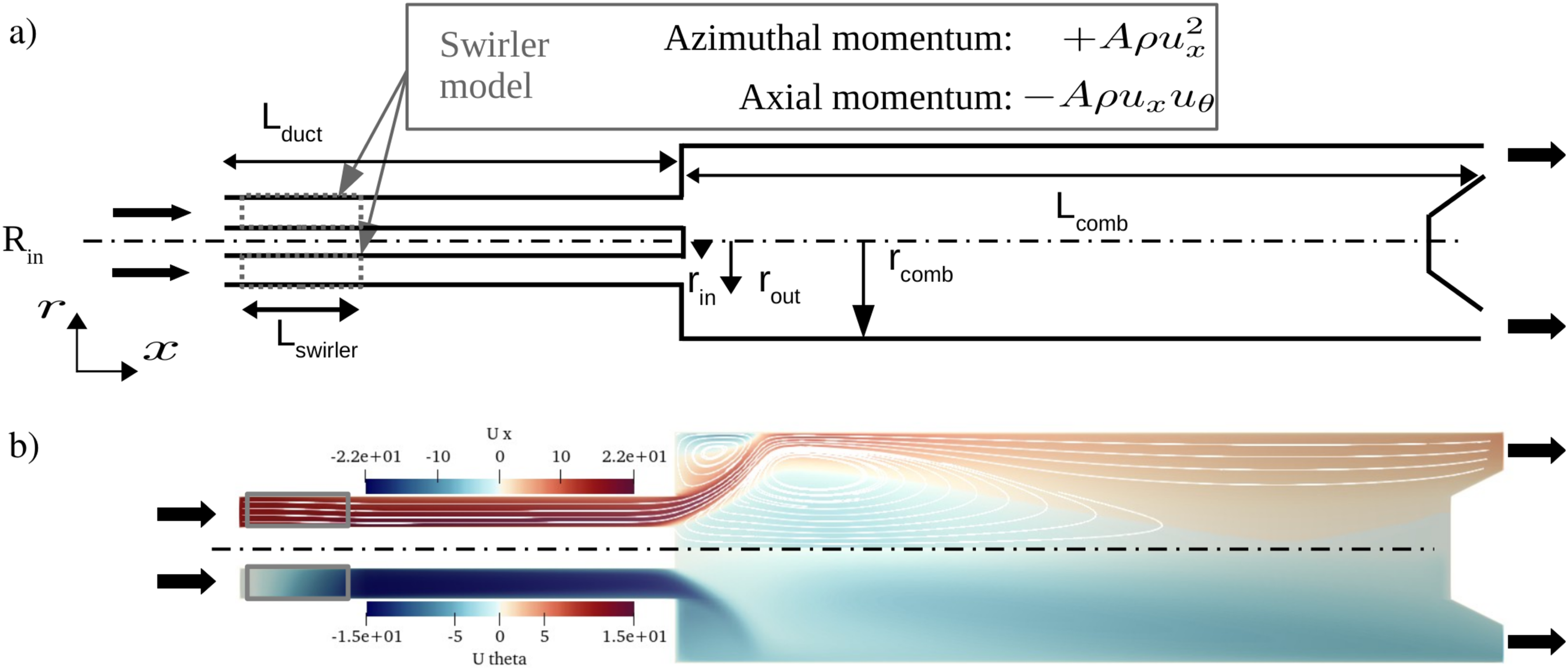
The configuration of interest depicted in Figure 1(a) and Table 1, is a cylindrical burner composed of an axial swirler with a central bluffbody and a flow expansion into a combustion chamber. This configuration is studied with an axial symmetry, in a cylindrical coordinate system
Bold values represent the base case.
Kiesewetter et al.10,16 proposed to model the axial to azimuthal momentum conversion in a swirler by a coupling term added to the azimuthal momentum conservation equation in a restricted region of the mixing duct, depicted in Figures 1 and 2,

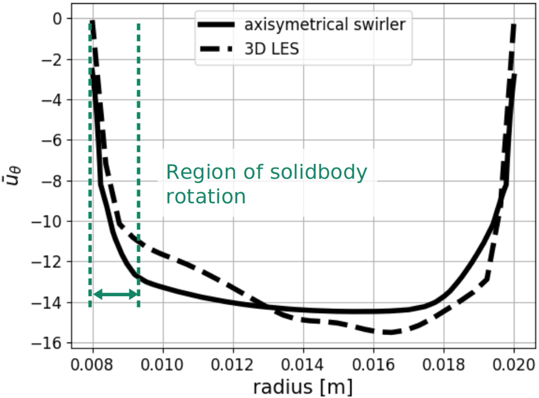
Radial profile of the base-flow downstream the swirler: time-averaged LES of a 3D resolved swirler 15 (dashed) and the present axisymmetrical model (solid). The region between the green dashed lines corresponds approximately to a solid body rotation. LES: large eddy simulation; 3D: three-dimensional.
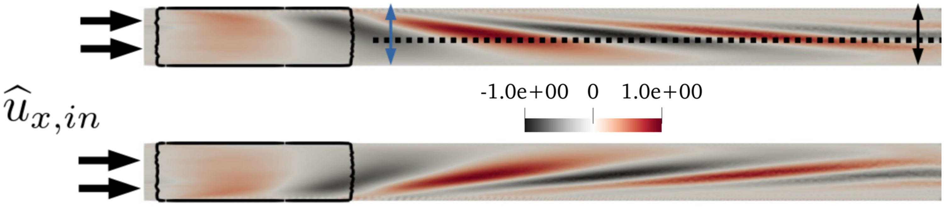
Zoom on the mixing tube. Azimuthal velocity fluctuation
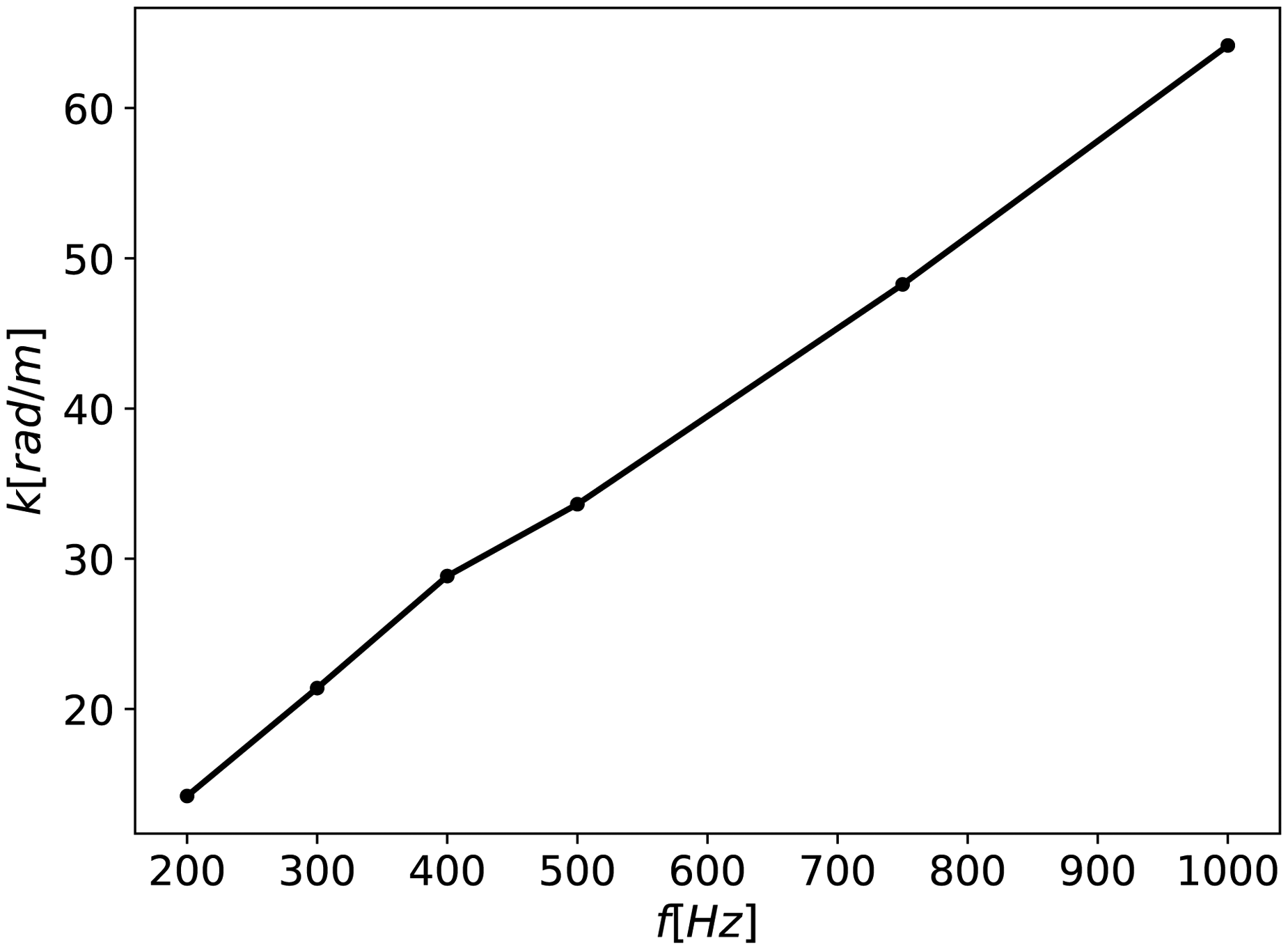
Dispersion diagram of
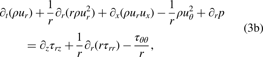
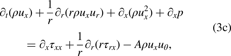
The state variables evolve according to Navier-Stokes equations, here in cylindrical coordinates,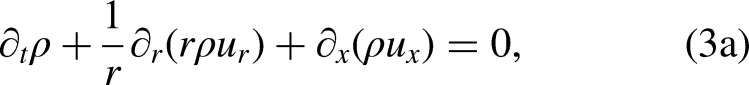


Assessment of the axisymmetrical swirler model
Linear fluctuations solution to (9) for an input forcing are verified against 3D LES results. Equation (9) is Fourier-transformed in time,
Azimuthal velocity fluctuations corresponding to swirl waves are indeed developing in the swirler section (Figure 3). The wavelength and wavenumber
Propagation of inertial waves in non-parallel flows
In this section, the velocity fluctuations from (9) subject to an inlet axial velocity forcing are compared against wave solutions from Albayrak et al.,
4
that reports on the dispersive behavior of swirl waves on a uniform inviscid flow. However, Albayrak et al.
4
considered that inertial waves propagate as planar waves in the axial direction but the present results are spatially resolved in the
To compare the present results with the planar waves of Albayrak et al.,
4
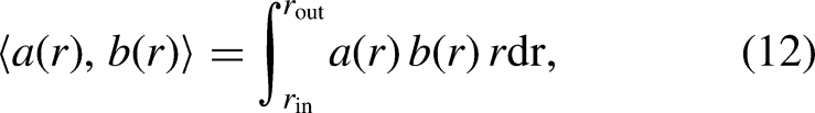
the perturbation fields
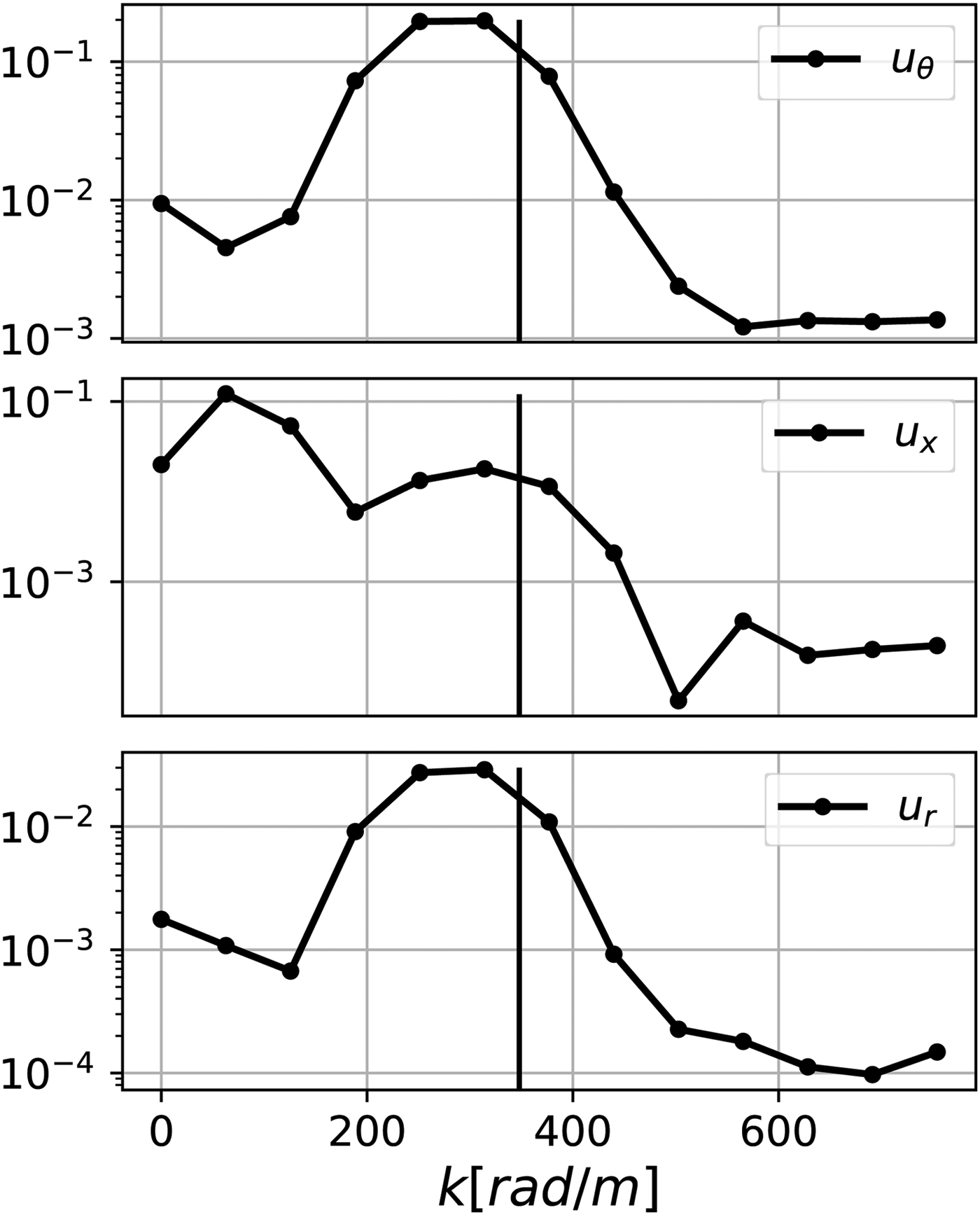
Absolute value of the spatial Fourier coefficients of
The three velocity components display a peak around the convective wavenumber
1
The radial profiles of velocity fluctuations 
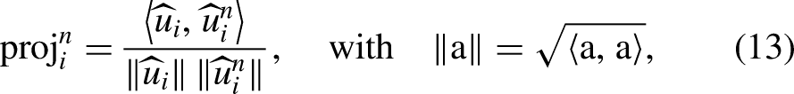
The projection of the azimuthal velocity fluctuation decays regularly, with the exception of an odd-even mode oscillation when the projection is made on the region of solid body rotation. This indicates that the first modes of equation (11) capture well the azimuthal velocity fluctuations. The steeper decay for the projection restricted to the inner region of approximate solid body rotation reveals that this agreement is even better in that region, which is expected since the mode shapes of equation (11) are derived on a uniform flow with solid body rotation. The same observations do not hold for the axial and radial components of the velocity fluctuations. In particular, the agreement of the axial velocity perturbation and the basis of mode shapes is worse in the region of approximate solid body rotation than when the entire radius is considered. The projection of the radial velocity fluctuation does not show smooth decay. Thereby, we conclude that the axial and radial velocity fluctuations associated with inertial waves in the present non-uniform and viscous flow do not correspond to axial and radial mode shapes of equation (11).
A possible reason for that observation comes from the non-parallel effects that affect the axial and radial components, that is, axial acoustic waves and shear in the boundary layer. Since the flow is non-uniform, these mechanisms can interplay in the linear regime. This is supported by the weaker agreement of
Fast and slow mode
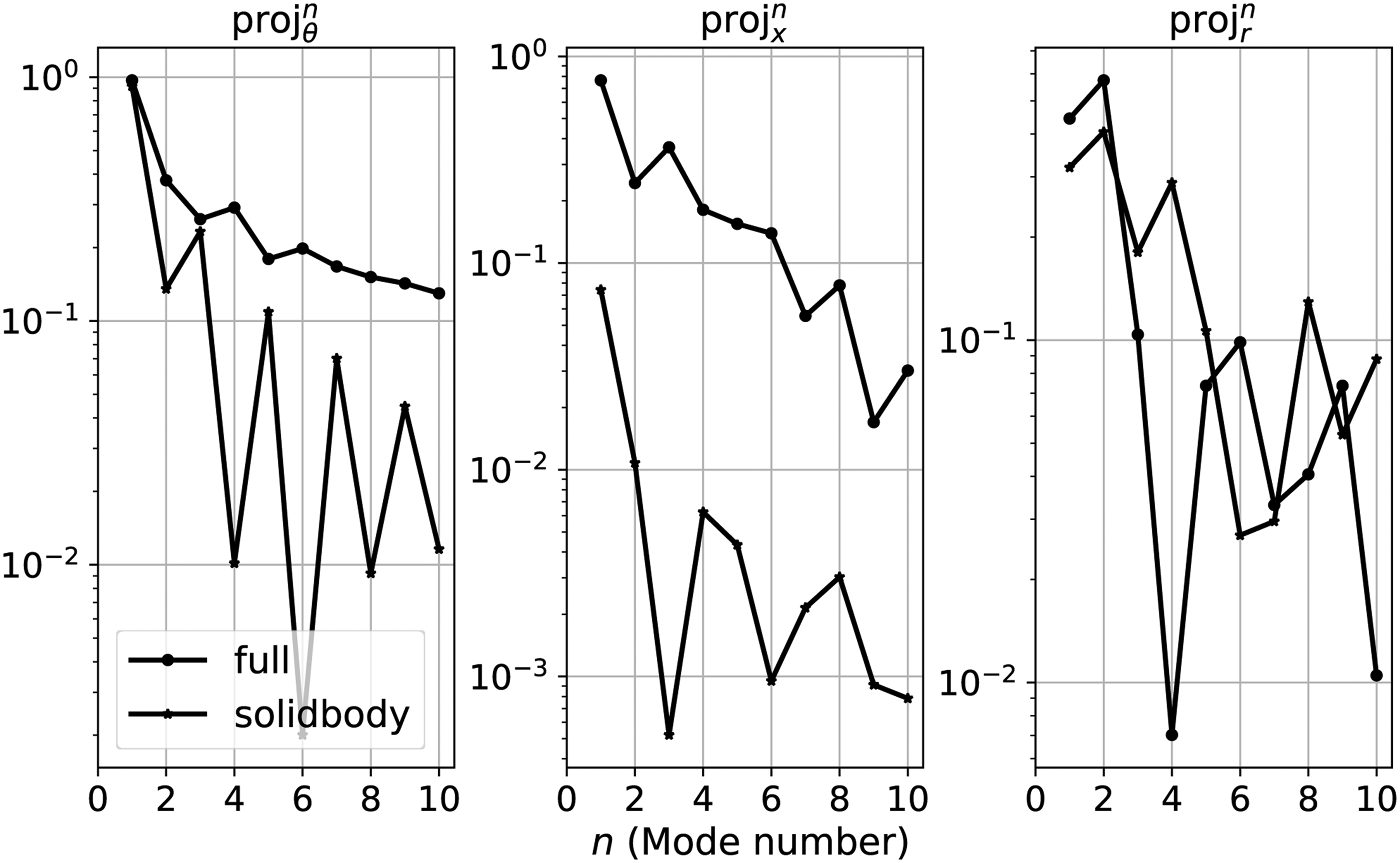
In the axial direction, however, the velocity fluctuation
If the characteristic length of 
This estimated wavenumber
This inversion of the fast and slow modes can be interpreted as a faster dispersion of the fast mode or amplification of the slow mode in the flow direction. However, larger wavenumbers tend to be damped faster by diffusion than smaller ones, so the effect of viscosity on the diffusion of small convective structures does not give a comprehensive explanation. This inversion of the dominant mode can result from the distortion of the azimuthal velocity profile
Amplification mechanisms
In this section, the role of inertial waves in amplification mechanisms is investigated through stability and resolvent analyses of linear fluctuations
Linear stability analysis
Equation (9) is Laplace-transformed and takes the form of an eigenvalue problem,

The loci of
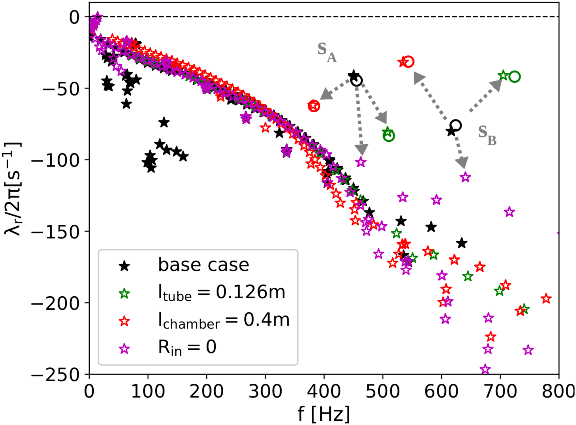
Stability map for the base case (filled stars) and the variations (empty stars), see Table 1. The two acoustic-like eigenvalues are denoted
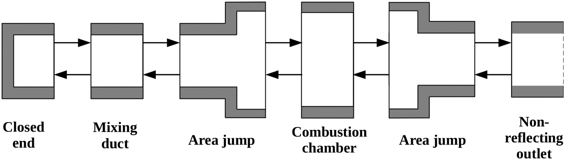
Acoustic network representation of the configuration of Figure 1(a).
Frequency selection in the mixing tube
Owing to the fact that all eigenvalues of equation (15) have a negative real part, none of the associated eigenmodes will be self-amplified. In other words, this flow behaves as an amplifier rather than an oscillator: it amplifies fluctuations when forced. As a consequence, the asymptotic stability analysis gives only a limited picture of the dynamic behavior of the system. This amplification behavior shows up in a resolvent analysis that unveils the interaction of the eigenmodes under a forcing. Due to non-normality, the stable eigenmodes interact together to build up the amplified response.23,24
In that perspective, we now consider the flow under an a harmonic force 
The resolvent analysis solves the following optimal amplification problem at various frequencies 


The optimal gains for the four configurations of interest show a one- or two-peak resonance Figure 10(a) at frequencies corresponding to the eigenfrequencies—that is, the imaginary parts—of
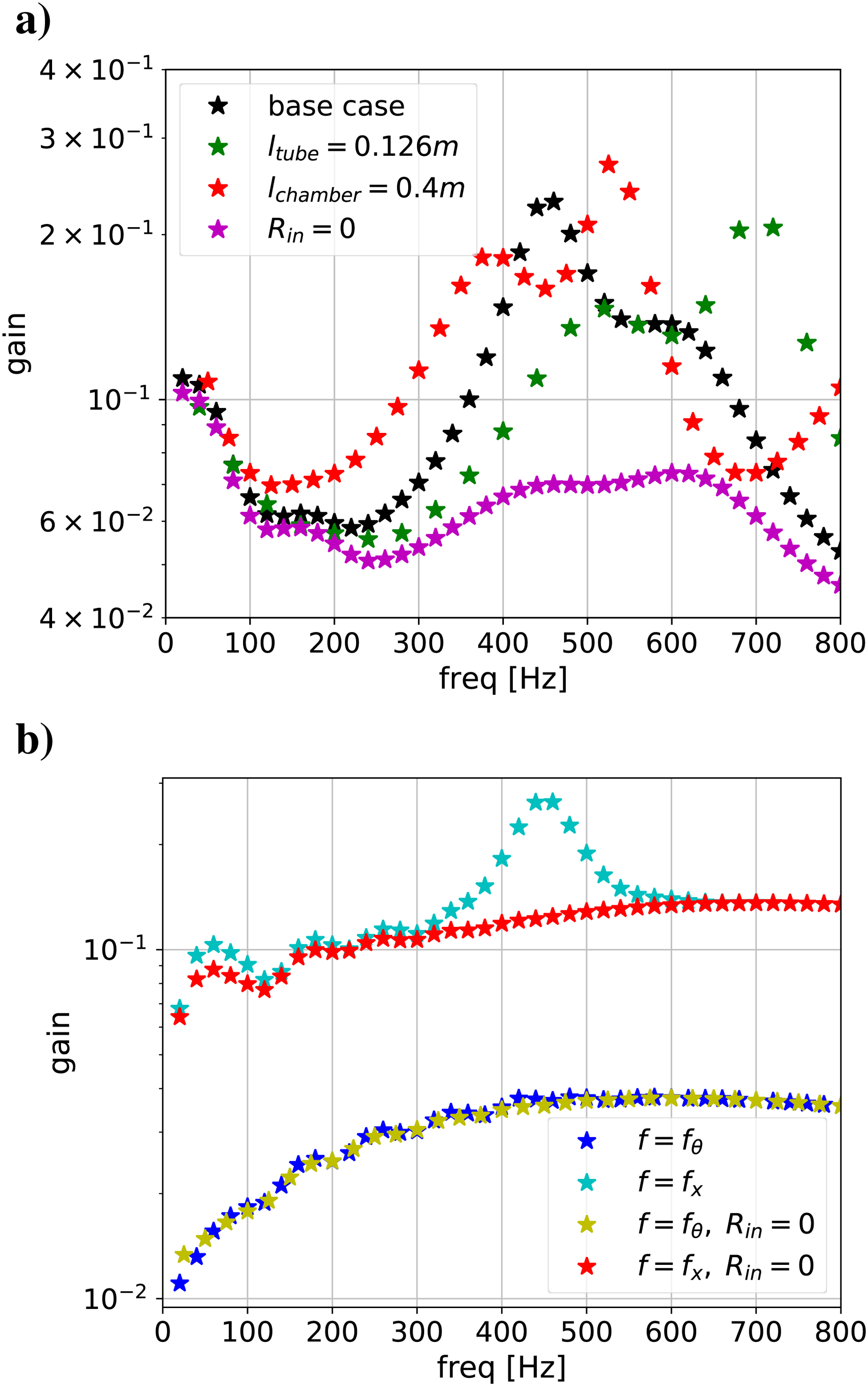
Optimal gains: (a)
This maximum amplification occurs when the forcing is applied on the axial momentum in the combustion chamber. The optimal forcing as shown in Figure 11(a) is distributed in the entire combustion chamber, with a spatial dependence mainly in the axial direction. This shape is similar to a longitudinal acoustic wave pattern. In addition, the same peak is obtained for a forcing on the axial momentum in the mixing duct as shown in Figure 10(b), but not for a forcing in the azimuthal momentum or when the inlet is non-reflecting. These elements indicate that the forcing that maximizes the amplification of fluctuations is the one that triggers the cavity modes of the mixing duct coupled with the combustion chamber. This means that the frequency of the optimal amplification mechanism is set by the acoustic mode that the coupled mixing tube and combustion chamber can sustain.
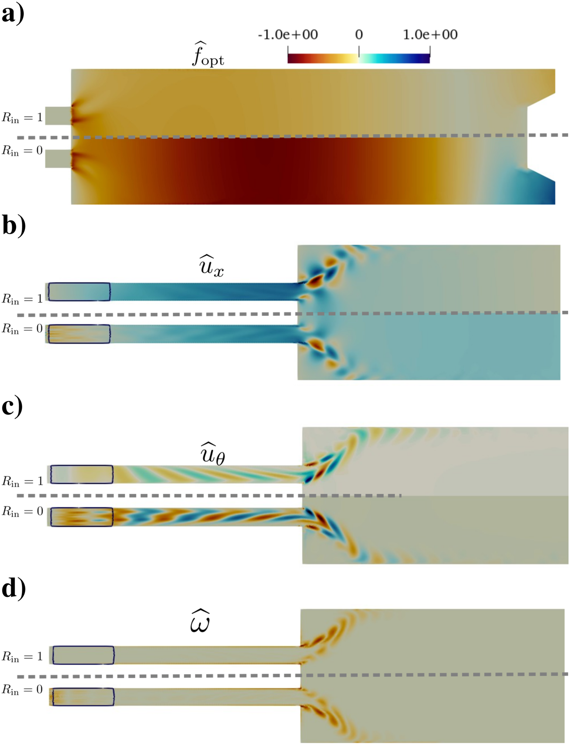
Forcing on the axial momentum equation in the combustion chamber with (upper halves) closed inlet or (lower halves) non-reflecting inlet: real parts of (a) the forcing
When forced in the mixing duct, the results can be compared to existing results on resolvent analysis of jets. The optimal forcings as shown in Figure 12(a) are dominated by tilted stripes in the direction of the shear, typical of the Orr mechanism, as shown by Schmidt et al.
29
This mechanism is dominant in jets for Strouhal number
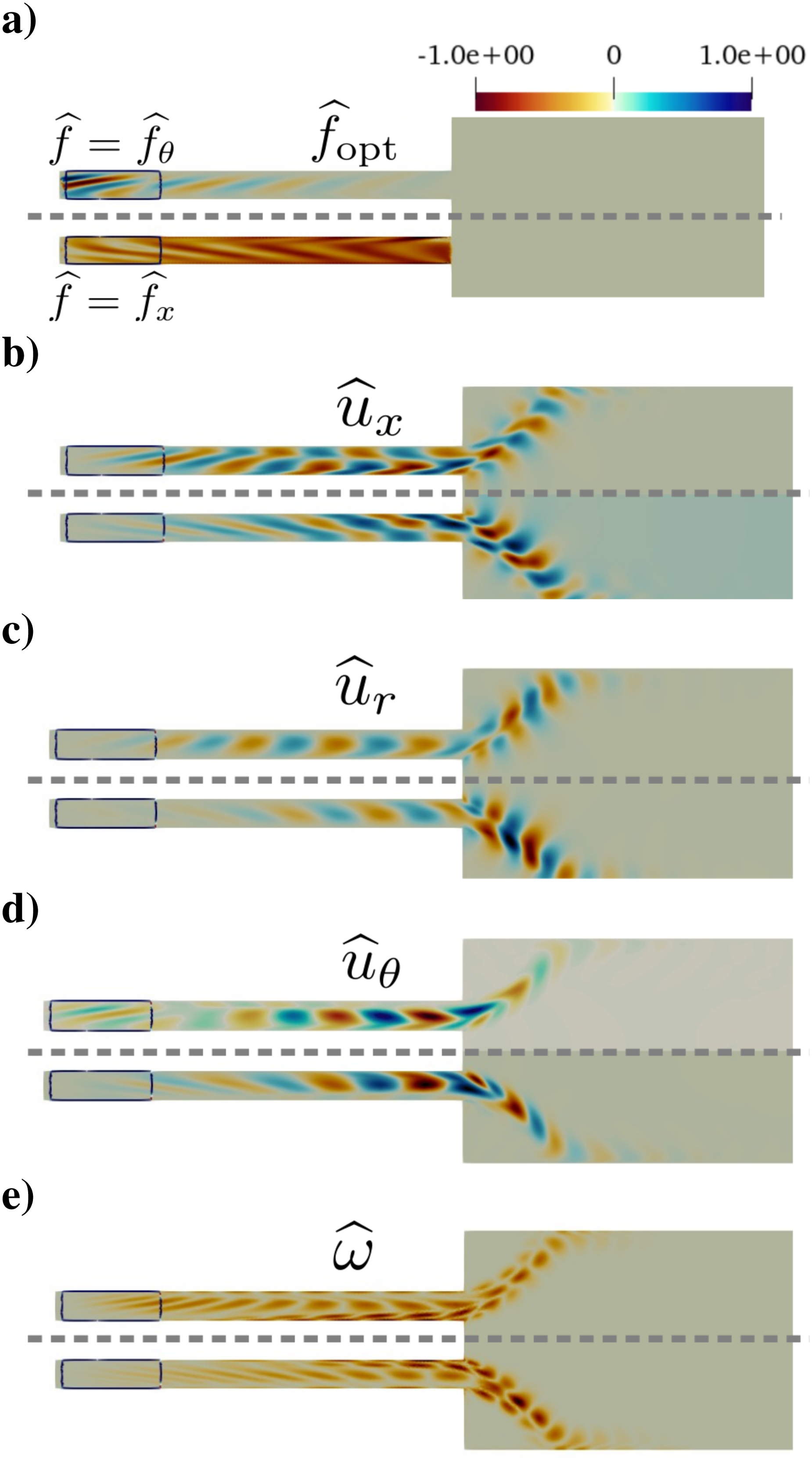
Optimal amplification at 454 Hz, for forcing in the MT: forcing on (upper halves) the azimuthal momentum or (lower halves) the axial momentum: (a) optimal forcing, optimal responses, (b)
Although a modal resonance has been identified in the gain, the optimal response cannot simply be associated with the least stable eigenvector—that is,
In the three geometrical configurations investigated, the least stable eigenvalue is the one showing the strongest acoustic-like fluctuation in the mixing duct and the strongest vorticity shed from the edges of the mixing duct. For the base case, the vorticity of
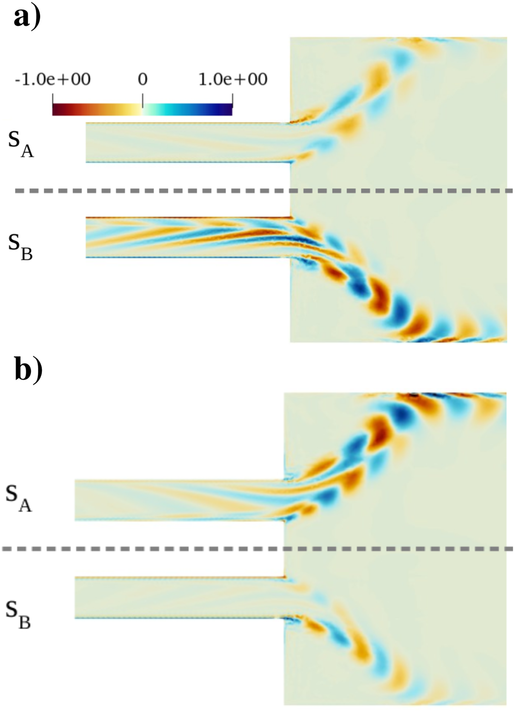
Real part of the
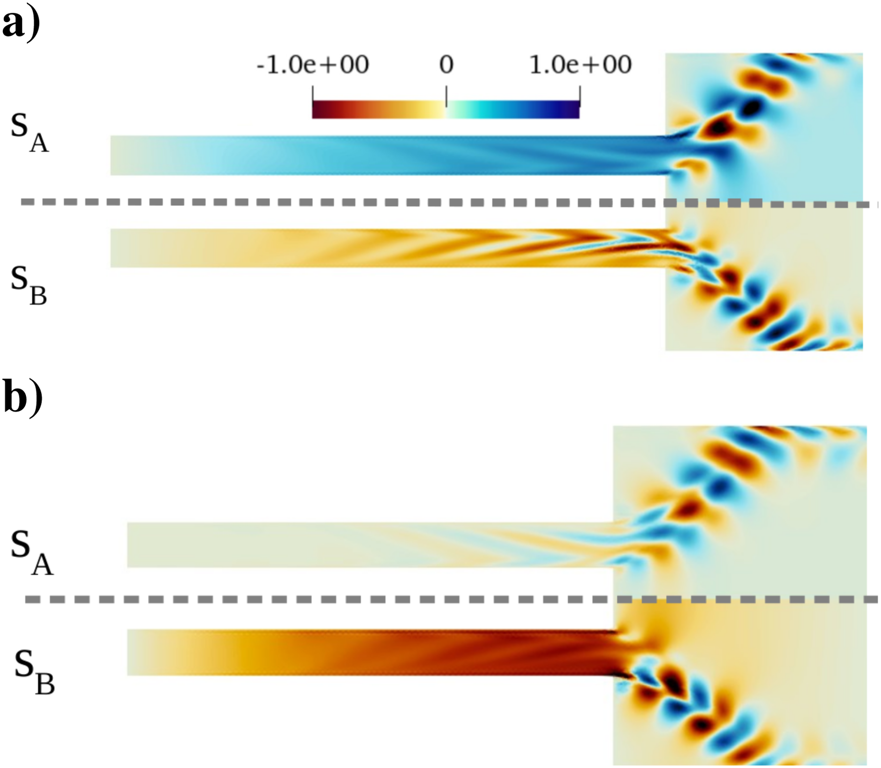
Real part of the
Mode-conversion process in the optimal amplification
The optimal response to a forcing in the combustion chamber displayed in Figure 11 shows an acoustic-like wave pattern in the mixing duct and a vorticity pattern close to those of the leading eigenmode. Such an observation is consistent with the modal amplification identified on the gain curves in Figure 10. This vorticity is amplified while propagating downstream by the Kelvin–Helmholtz mechanism and eventually reaches the position where a flame can be stabilized. However, the optimal response is not similar to the least stable eigenmode since it includes azimuthal velocity fluctuations generated in the swirler section by velocity fluctuations of the upstream acoustic wave traveling in the mixing tube as shown in Figure 11(b). These azimuthal fluctuations are also generated in the case of a non-reflecting inlet in Figure 11 (lower halves), that is, in a purely anechoic setup. This proves that their generation is also possible without reflection at the inlet boundary as an actual conversion of upstream propagating acoustic waves originating from the combustion chamber.
In the purely anechoic case, only inertial waves can close the feedback loop by propagating back to the combustion chamber. The present results illustrate that the “mode conversion” process is at play in the optimal amplification mechanism. The mode conversion refers to the process that generates swirl fluctuations from acoustic waves impinging on a swirler. 6 Such a conversion is based on the interactions between sound and vorticity in the linear regime close to walls described by Chu and Kovasznay, 34 and has often been modeled via the “actuator disk” theory. 35 This process was already invoked in experiments and CFD simulations to explain the generation of swirl fluctuation, and it is now found to be part of optimal amplification. Additionally, it is not visible if not in the frequency range of the peak or for suboptimal gain, which makes the mode conversion process peculiar to the most efficient amplification mechanism.
The response of the swirler is non-negligible for all types of forcing. In addition, the optimal forcing in the swirler section of the mixing duct is non-negligible. It is even principally clustered in the swirler section for forcing on the azimuthal momentum, as shown in Figure 12(a). Firstly, this reveals that the swirler section is a region of interest with respect to the optimal forcing, and confirms the necessity of accounting for the knowledge of the flow close to the swirler suggested by Lückoff et al. 36 and Müllet et al. 14 The reversibility of the mode conversion process is illustrated by the response to the forcing on the azimuthal momentum, as shown in Figure 12 (upper halves). In that case, the forced azimuthal momentum is preferentially converted into axial velocity fluctuations instead of generating azimuthal velocity fluctuations. Indeed, some tilted azimuthal velocity fluctuations are generated in the swirler but tend to vanish at the swirler exit. In contrast, axial velocity fluctuations are advected downstream and re-generate azimuthal velocity fluctuations further downstream, with wave packets perpendicular to the main stream. However, in the present case, these axial velocity fluctuations correspond to vorticity perturbations and not acoustic modes.
In the case of forcing on the axial momentum, as shown in Figure 12 (lower halves), the optimal forcing is a superposition of tilted convective structures with an acoustic structure corresponding to a quarter wavelength. The response is similar to the case of forcing on the azimuthal momentum, except that all three components of velocity fluctuations are produced within the swirler and amplified while propagating downstream. These two cases, that is, forcing in the mixing tube, illustrate that the mode conversion process is at play in all the optimal amplification mechanisms investigated.
Discussion of the results
The results of the resolvent analysis show that the optimal forcing in the combustion chamber corresponds to the pattern of an acoustic cavity mode, as shown in Figure 11(a). An unsteady heat source in the combustion chamber is very likely to produce such an acoustic field, and therefore to trigger the optimal amplification mechanism. This mechanism consists of a quarter-wave mode in the mixing duct coupled with the Kelvin–Helmholtz mechanism at the mixing duct edges and a mode conversion in the swirler producing swirl fluctuations.
The role of swirl fluctuations accounts here through their axial component. Axial velocity fluctuations stemming from both swirl and acoustic waves trigger vorticity shedding at the edges of the duct, drawing two paths for the feedback. This vorticity is then amplified by the Kelvin–Helmholtz mechanism. In the case of a flame stabilized in the combustion chamber, the vorticity is advected to the flame brush and increases or decreases the flame surface, which in turn modulates the heat release rate and produces some acoustic forcing on the axial momentum. The resulting feedback loop is depicted in Figure 15. The axial component of inertial waves was analytically evidenced by Albayrak et al. 4 and is observed in the present work on a realistic flow.
Flame-flow feedback loop.
The existence of two paths for vorticity generation implies the existence of two time delays in the flame-flow interaction, and therefore a higher propensity for unstable feedback to arise. The time delay of the acoustic wave is negligible, whereas the time delay of the inertial wave depends on its propagation velocity and the position of the swirler. These two time delays also control whether the contributions of inertial and acoustic waves to the total axial velocity fluctuation are in phase, which is necessary to maximize the velocity at the mixing duct exit. This is a reminder that the propagation speed of inertial waves is a crucial parameter in the feedback loop. However, as explained in the second section, none of the fast or slow modes was clearly dominant in the present study. Nevertheless, the radial non-uniformity of the convection speed is expected to have a more substantial impact than the dominance of the fast or slow mode. Indeed, inertial wave structures are tilted by the radial non-uniformity of the mean flow. This change in the orientation of the convective structures impacts the constructive or destructive nature of the interplay between acoustic and inertial waves.
This optimal amplification mechanism has been shown to set off a frequency selection relying on acoustic resonance in the coupled mixing duct and combustion chamber. Since the ratio of the area jump in between these two elements is not large enough to fully decouple the acoustic modes existing in each of them, it is not possible to completely characterize these modes. However, the acoustic network model of the present configuration shows that both of the eigenmodes
Conclusion and perspectives
The present work has shown the existence of inertial waves in a swirling flow representative of a swirl burner, that is, compressible, non-parallel, and turbulent. The mode conversion process and inertial waves are key features of the most efficient amplification mechanisms. In the context of combustion, unsteady heat release rate is likely to trigger such an optimal amplification mechanism involving inertial waves. The flow under study is computed via an axisymmetrical RANS model, including a modeled swirler. The capability of such an axisymmetrical modeled swirler to reproduce the static and dynamic behaviour of an actual swirler is verified against a 3D LES. The non-uniformity of the flow makes it difficult to conclude on the dominance of the “fast” or “slow” mode of the inertial waves, as discussed by Albayrak et al. 4 and Lückoff et al. 36 However, the analytical mode shapes derived by Albayrak et al. 4 on an inviscid uniform flow agree with the azimuthal velocity fluctuations observed in the flow under investigation in the present work. Optimal amplification mechanisms are identified thanks to a resolvent analysis, including the modeled swirler. The results of the resolvent analysis first show that a significant part of the optimal amplification mechanism takes place in the swirler region, if not the optimal forcing itself. Hence, the inclusion of the swirler in the analysis is critical. The optimal amplification mechanism presents a frequency selection driven by a quarter-wave acoustic mode in the mixing duct. Two acoustic modes are competing in that case, and the dominant one is the mode enhancing the strongest streamwise Kelvin–Helmholtz mechanism at the mixing duct exit.
The conclusions of the present analysis can be further verified on a reactive LES, in particular, whether an unsteady heat source in the combustion chamber triggers the identified optimal amplification mechanism. The swirl intensity is also expected to significantly impact the results and should be investigated.
Footnotes
Acknowledgements
The first author thanks Christoph Hirsch for his insight into the axisymmetrical swirler model. The authors gratefully acknowledge the Leibniz Supercomputing Centre for providing computing time on its Linux-Cluster. This work was carried out within the SWJET project funded by the Deutsche Forchungsgemeinschaft (DFG, German Research Foundation)—contract no. 441269395—and the Forschungsvereinigung Verbrennungskraftmaschinen e.V. (FVV, Research Association for Combustion Engines)—contract no. 6014212.
Declaration of conflicting interests
The author(s) declare no potential conflicts of interest with respect to the research, authorship, and/or publication of this article.
Funding
The authors disclosed receipt of the following financial support for the research, authorship, and/or publication of this article: This work was funded by the Deutsche Forchungsgemeinschaft (DFG, German Research Foundation) – contract n°441269395 - and the Forschungsvereinigung Verbrennungskraftmaschinen e.V. (FVV, Research Association for Combustion Engines) - contract n°6014212.