
Abstract
Structures of laminar non-premixed ethanol/air spray flames in the axisymmetric counterflow configuration are studied under fuel-rich conditions by means of numerical simulations. The monodisperse ethanol spray is carried by air and directed against an air stream. Both streams enter at 300 K, and the system is at atmospheric pressure. Up to three different structures of these flames for identical boundary and initial conditions are identified, and regime diagrams are presented that show their conditions of existence in terms of the gas strain rate on the spray side of the configuration,
Introduction
Spray flames are relevant in many practical combustion systems such as industrial furnaces, liquid propulsion systems, household burners, and internal combustion engines. 1 In turbulent spray flames, the consideration of detailed chemical reactions is inevitable to study pollutant formation. Laminar flame structures are the basis of flamelet models, 2 developed for the simulation of turbulent gas flames in a computationally efficient way.3–5 The advantage of using structures of laminar flames in the counterflow configuration is the possibility of transferring the two-dimensional gas equations into a one-dimensional formulation through a similarity transformation, 2 which allows the use of detailed chemical reaction mechanisms. These laminar flame structures are incorporated into turbulent flame simulations 6 in which the turbulent nature of the flow field is accounted for through the use of probability density functions. In non-premixed combustion, the independent variables typically are the mixture fraction and its scalar dissipation rate.2,6 The flamelet model is appropriate for high Damköhler numbers.
Flamelet models for turbulent combustion are beneficial if detailed chemical reactions are to be considered to predict pollutant formation. If turbulent spray flames are modeled, most often, laminar gas flamelets are incorporated.7,6 The groundbreaking work of Continillo and Sirignano, 8 who showed that the similarity formulation mentioned above for gas flames is also valid for dilute spray flames in the counterflow configuration, enabled their use in spray flamelet simulations. 9 The advantage of this formulation is the consideration of the energy consumption due to the evaporation of the spray directly in the laminar spray flamelets. The formulation of Continillo and Sirignano 8 was extended to account for variable gas properties and detailed chemical reactions by Gutheil and Sirignano. 10 This new formulation allows for the consideration of pollutant formation in turbulent spray flames through the use of the spray flamelet model.9,7,11
Flamelet models for spray combustion including spray flamelet libraries are more complex than gas flamelets since they do not only depend on the mixture fraction and its scalar dissipation rate (or the gas strain rate) but also on the initial gas and spray velocities, the equivalence ratio, and the initial droplet size of the spray. 10 The effect of varying these parameters was studied for different fuels.8,10,9,12,13 Moreover, partially premixed systems were investigated. 14 All these investigations concerned stoichiometric conditions.
Continillo and Sirignano 8 postulated that the governing equations of laminar counterflow spray flames might have multiple numerical solutions. Gutheil 15 found two different solutions for the same boundary and initial conditions for stoichiometric methanol/air spray flames. One of these spray flame structures consists of two chemical reaction zones one of which resides on the spray side of the counterflow configuration and the second one on the gas side. The second spray flame structure has a single chemical reaction zone on the spray side, that is, that on the gas side does not exist. In that study, it was demonstrated that the gas-sided chemical reaction zone has a similar structure as a pure gas flamelet. Note that the chemical reaction zones are identified in terms of gas temperature, that is, the chemical reactions typically occur in the hot flame zone even though some reactions may also occur in regions that are off the peak gas temperature.
Xie et al.
16
exhibited the coexistence of collocated, distributed, and cool flames when they numerically studied canonical counterflow spray flames at relatively low strain rates using different low-temperature chemical reaction mechanisms in a one-dimensional configuration. Carpio et al.
17
studied two-dimensional dodecane spray flames with carrier nitrogen against an air stream using a one-step chemical reaction, and they identified two solutions where one is a diffusion flame and the second is flameless. Vié et al.
18
identified the bifurcation of a monodisperse
Ying et al.
20
studied fuel-rich ethanol/air spray flames in the counterflow configuration. They also found two different spray flame structures for a monodisperse spray with a fixed initial droplet radius of 50
The existence of multiple (spray) flame structures may lead to flame instabilities as reported by Karaminejad et al. 21 in an experimental study of flame spray pyrolysis for nanoparticle formation where flame pulsation and consequently flame stability strongly depend on spray characteristics. Kiran and Mishra 22 performed an experimental investigation of flame stability of a simple liquefied petroleum gas (LPG) jet diffusion flame, and they showed that flame stability affects the pollutant emission characteristics in these flames. For real applications, the coexistence of multiple flame structures is related to the phenomenon of flame pulsation, which may occur in situations in which abrupt transitions between the different flame structures occur.
The phenomena of droplet reversal and oscillation were found in experiments by Puri and Libby.
23
They studied the trajectories of
In the present study, the work of Ying et al., 20 who identified two different spray flame structures for the same initial and boundary conditions, is extended to cover a wide range of fuel-rich ethanol/air spray flames for monodisperse sprays with different initial droplet radii, equivalence ratios, and strain rates. The structures for these conditions sometimes show unique solutions and for some conditions, two or three different spray flame structures for the same initial and boundary conditions are identified. Conditions under which these structures exist or coexist and the underlying physical processes for the transition of a structure into another one are analyzed and discussed. Also, the influence of these findings on the spray flamelet formulation of turbulent spray flames is outlined.
Mathematical formulation
The steady two-dimensional governing gas equations for a viscous laminar flow at a low Mach number with source terms to account for the dilute spray are non-dimensionalized and transformed into one-dimensional equations using a similarity transformation.10,8 The transport properties of the ethanol/air spray are variable, 25 and a detailed chemical reaction mechanism is used. 26 The monodisperse ethanol spray is carried by air and directed against an air stream at atmospheric pressure, both streams are at 300 K. Depending on the initial spray conditions, the initially monodisperse spray may reverse and oscillate around the gas stagnation point, leading to a locally polydisperse spray. 10 The resulting equations and the numerical solution procedure are reported earlier for stoichiometric spray flames in the same setting.8,10
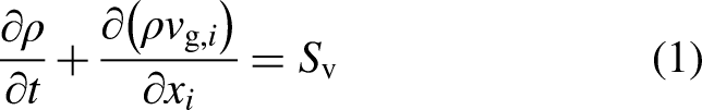
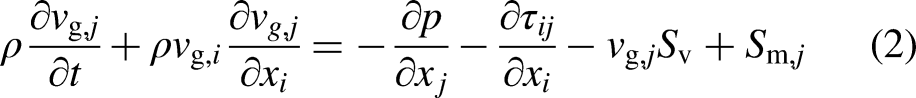
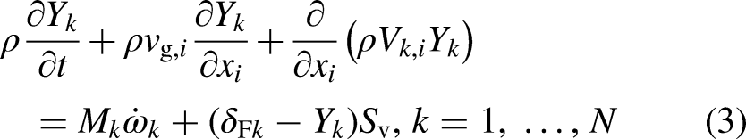
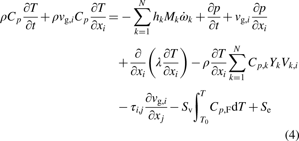
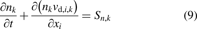
The general conservation equations of mass, momentum, mass fractions of chemical species, and energy under consideration of spray source terms accounting for the interaction of the gas and the spray are written as
10
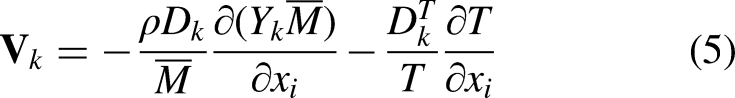
The diffusion velocity
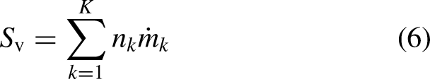
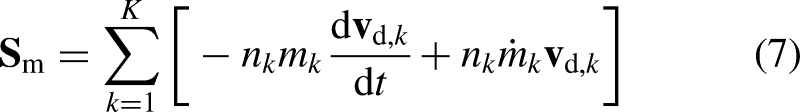
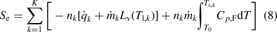
The source terms for mass
The droplet number density,
The physical gas properties are calculated following the work of Kee et al. 25 In particular, the multicomponent diffusion model is used. Variable liquid properties are provided by Gutheil. 12
The governing equations are non-dimensionalized with specific reference values, 10 and a similarity transformation for the two-dimensional gas phase equations is used so that the gas equations become one-dimensional.8,10
The resulting equations are solved numerically, and in the remainder of the paper, the gas strain rate,
Results and discussion
Numerical simulations are performed for a monodisperse ethanol spray with carrier gas air directed against an air stream. The system is at atmospheric pressure with initial gas and spray temperatures of 300 K and an equivalence ratio
Regime diagrams
Diagrams for the existence of the multiple spray flame structures for the same initial and boundary conditions for initial droplet radii,
A comparison of the structures displayed in Figure 1 shows that the flame structures with two reaction zones are more stable than those with single chemical reaction zones since they persist to high strain rates. The larger the initial droplet radius, the smaller the range of strain rates in which numerical solutions are obtained. If multiple structures exist, the single chemical reaction zone on the gas side of the configuration is preferred for the larger initial droplet sizes, whereas the spray structures with a spray-sided single chemical reaction exist mainly for the spray flames with the smallest initial droplet radius of 10
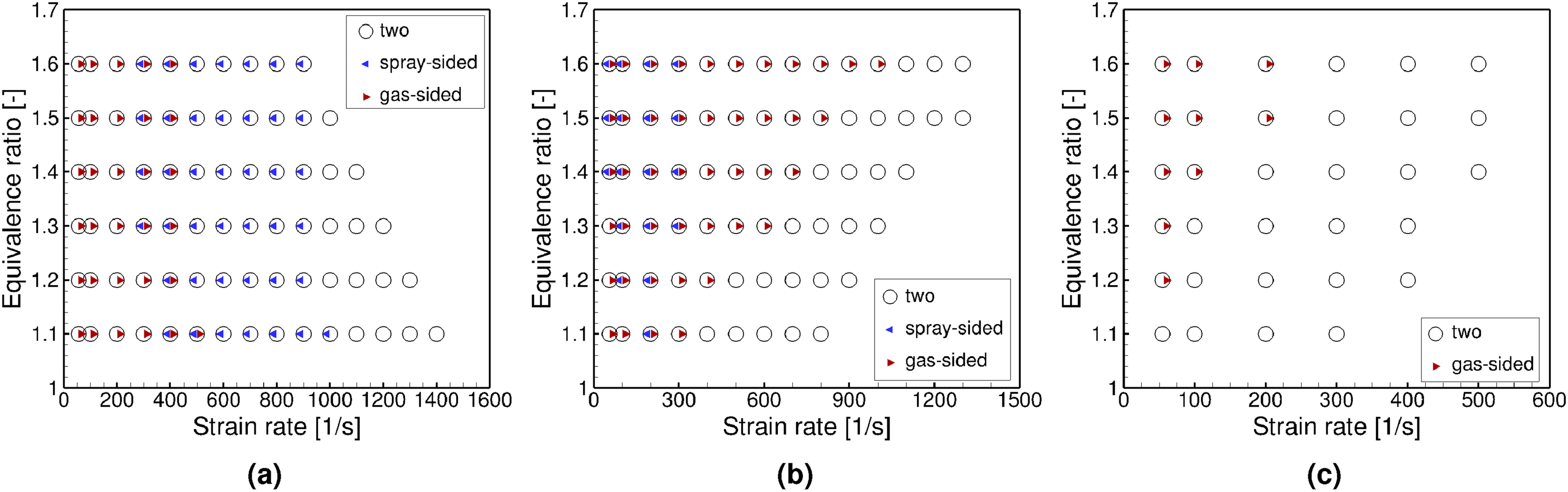
Regime diagrams of spray flame structures with single spray- or gas-sided reaction zones or two reaction zones for different initial droplet radii
Characteristics of the different spray flame structures
First, a condition is selected for which all three different spray flame structures exist so that their characteristics may be analyzed and discussed.
Considering Figure 1, all three different spray flame structures exist for an initial droplet radius
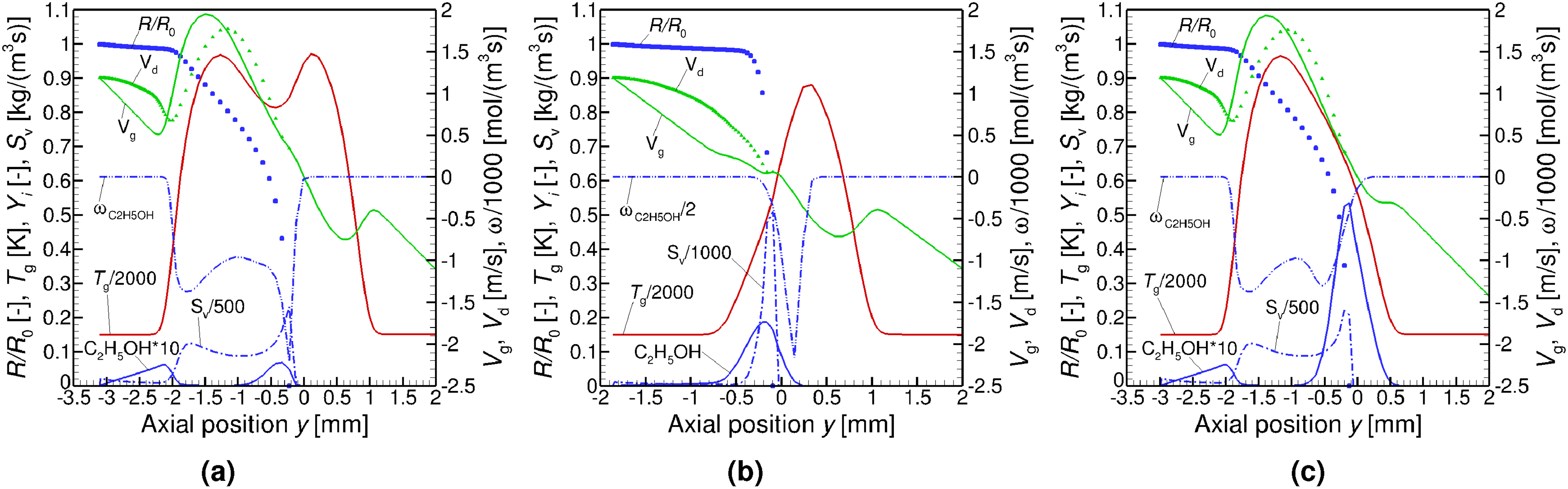
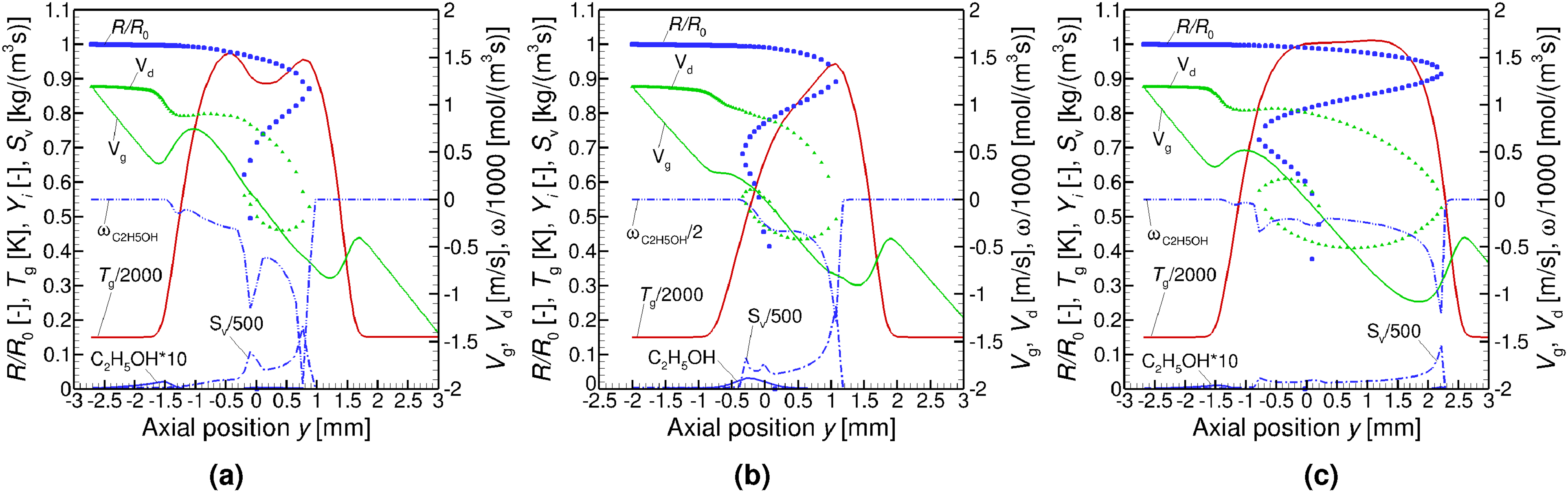
Different flame structures for
The monodisperse spray flame structures with a relatively small initial droplet radius of 10
The gas and droplet velocities
Two more different spray flame structures are found with single chemical reaction zones. In Figure 2(b), the reaction zone resides on the gas side of the configuration whereas in Figure 2(c), it locates on the spray side. The principal spray flame structure seen in Figure 2(b) was identified in an earlier study by Ying et al.
20
for
A comparison of the spray flame structures displayed in Figure 2(a) and (c) shows that the spray-sided structure in Figure 2(a) is almost the same as that in Figure 2(c) whereas the structure in Figure 2(b) is qualitatively different. Gutheil 15 identified the two different spray flame structures seen in Figure 2(a) and (c) for methanol/air sprays that show two chemical reaction zones and one on the spray side of the configuration, and it was argued that the spray-sided chemical reaction zones are similar or even identical to the gas-sided reaction zone being extinguished in the situation with a single chemical reaction zone on the spray side, which is also valid here. However, the spray flame structure with separated chemical reaction zones and vaporization zones displayed in Figure 2(b), is new and qualitatively different since it shows separated vaporization and chemical reaction zones as discussed by Ying et al. 20 However, this is the first study to show that three different spray flame structures may exist for the same initial and boundary conditions for fuel-rich spray flames in the counterflow configuration.
The existence of the different spray flame structures may be useful to explain spray flame pulsation that may occur in spray flames. 28 The spray flame structure displayed in Figure 2(b) is very interesting in the context of micro-explosion of droplets which may occur in multicomponent droplets that reside in a relatively hot environment outside the main combustion zone. The scenario shown here would provide the perfect conditions for puffing and micro-explosions 29 to happen.
Small droplets evaporate entirely on the spray side of the counterflow configuration as can be seen in Figure 2. As the initial droplet radius is increased, the flame structures change considerably.
As the initial droplet radius is increased from 10 to 30
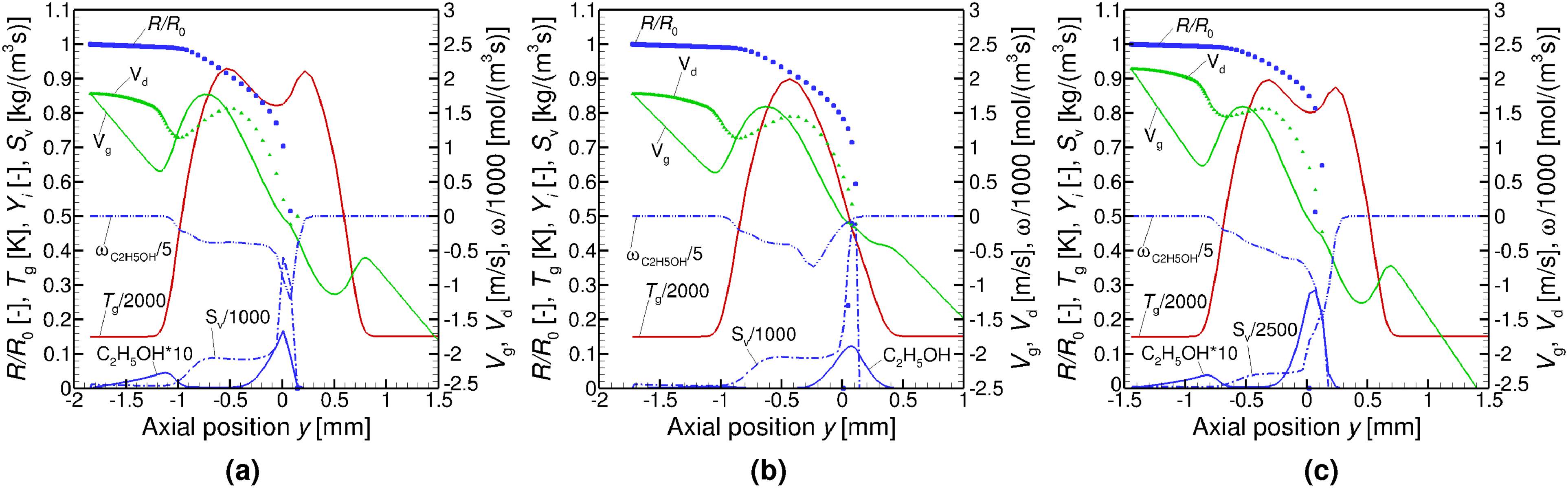
Different flame structures for
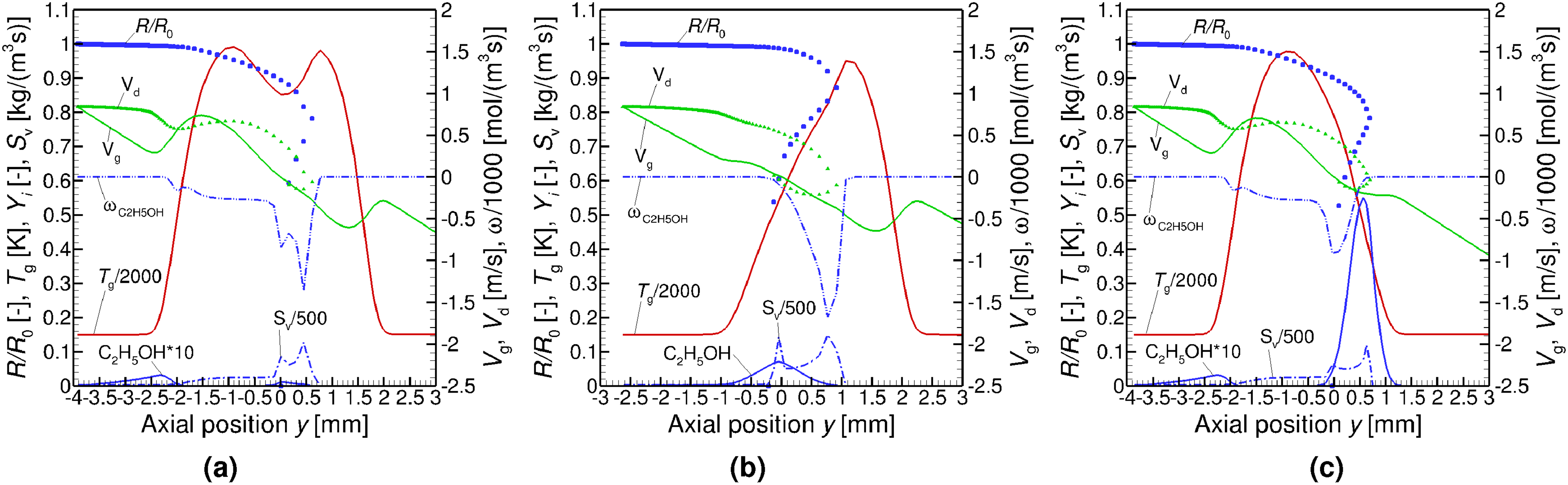
The regime diagrams in Figure 1(a) and (b) for initial droplet radii of 10 and 30
Figure 3 displays the three corresponding structures to those in Figure 2 for the larger initial droplet radius and the reduced gas strain rate at the spray boundary. The most important difference is the deep penetration of the larger droplets into the configuration: the droplets cross the stagnation plane and reverse due to the opposed airflow, and the initially monodisperse spray becomes locally polydisperse. The drag force of the larger droplets reflects in the profiles of the droplet velocities. At the positions of droplet reversal, there is enhanced evaporation due to the prolonged residence time of the droplets at that position as can be seen in the profile of
The principal characteristics of the three different spray flame structures are maintained for the larger initial droplet radii. The spray flames become broader and the evaporation zone is enlarged. The location of droplet reversal resides inside the chemical reaction zone if there are two chemical reaction zones, see Figure 3(a), whereas, in the situation of single chemical reaction zones, they do not locate inside but closer to the spray or the gas side of the configuration for the gas- and spray-sided chemical reaction zones, respectively, as displayed in Figures 3(b) and (c). It is also found that the droplets in the structure with one chemical reaction zone on the spray side of the configuration cross the chemical reaction zone due to their larger momentum. At higher initial droplet radii, not only droplet reversal but also oscillation occurs and under that condition, triple flame structures are not found.
Scenarios for the breakdown of one or the other spray flame structures will be discussed in the next subsection.
Transition mechanisms of spray flame structures
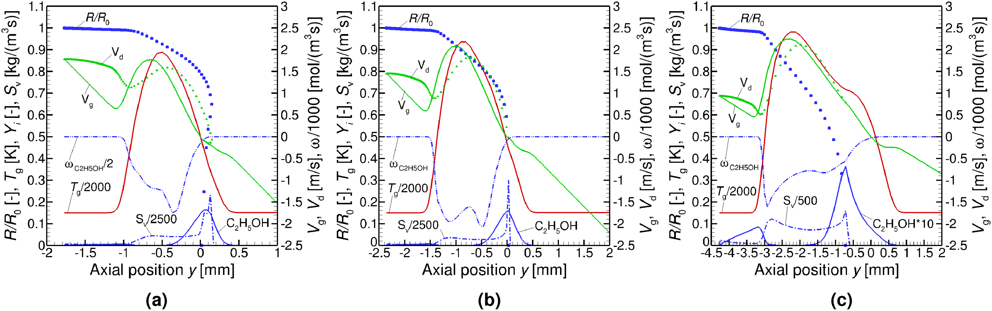
The triple flame structures are lost for initial droplet radii of 50
If the gas strain rate is increased from 200/s to 400/s at
Flame structures at
At the larger initial droplet radius of 50
Thus, droplet reversal and oscillation caused by the increased momentum of larger droplets lead to the transition to the reduced number of multiple flame structures and eventually to a unique structure. The droplet penetration into the chemical reaction zone and toward the gas side of the configuration caused by the droplet reversal and possible oscillation around the stagnation plane enhance the combustion of the spray flame which again feeds the flame with fuel vapor. Thus, the strong bond between the vaporization of the spray, which on the one hand requires energy from the combustion zone and on the other hand feeds the reaction zone with fuel vapor, and the chemical reactions, which consume the fuel vapor and deliver the energy for the vaporization, characterizes the spray flames and the transition between the different spray flame structures. Moreover, the droplet motion and location of the droplets within the counterflow configuration determine the location of the vaporization and combustion zones, and the droplet motion differs for monodisperse sprays with different initial droplet radii.
The transition mechanism of three different spray flame structures to two at
Flame structures at
Figure 6 shows the loss of the spray-sided flame structure at
Spray-sided flame structures at
In summary, the spray flame structures with two reaction zones exist for all cases under investigation and they are most stable compared to the spray flame structures with a single chemical reaction zone. Triple flame structures are only found at low initial droplet radii and moderate gas strain rates; the spray flames with the largest initial droplet radius of 50
Transition mechanisms for the loss or development of spray flame structures are dominated by the sensible interaction of energy-consuming vaporization, the location of the droplets within the counterflow configuration, and the exothermic chemical reactions.
The impact of the multiple spray flame structures on spray flamelet modeling is not as severe as anticipated since the spray-sided chemical reaction zones of the structure with two chemical reaction zones are more or less identical to those of the single spray-sided flame structure and the gas-sided part of the chemical reaction zone is essentially a gas flame as found in earlier studies. 15 However, the finding of the single flame with the gas-sided chemical reaction zone 20 is new and requires special treatment. The novelty of the present investigation is the identification of triple spray flame structures for certain conditions found in fuel-rich spray flames.
Conclusions
Multiple structures of laminar fuel-rich ethanol/air spray flames in the counterflow configuration are studied numerically. A monodisperse ethanol spray with carrier gas air is directed against an air stream at atmospheric pressure for initial droplet radii of 10, 30, and 50
Up to three different flame structures are found for the same initial and boundary conditions. Two different spray flame structures with a single chemical reaction zone either on the spray or the gas side of the counterflow configuration are identified, and the third spray flame structure consists of two chemical reaction zones on either side of the stagnation plane. Generally, spray flame structures with two chemical reaction zones are the most stable. For small initial droplet sizes, the flame with the spray-sided reaction zone is more stable than that on the gas side whereas for larger initial droplet radii, this is reversed due to the higher momentum of the larger droplets that penetrate deeper into the counterflow configuration.
The conditions under which the different flame structures coexist are analyzed and discussed. The existence of two different spray flame structures for fixed boundary and initial conditions was discussed in earlier studies,15,20 but the identification of three different structures is new. For stoichiometric flames, the spray flame structure with a single chemical reaction zone on the spray side was identified before, 15 and it was argued that that spray flame structure shows the same characteristics as the spray-sided structure of the flame with two chemical reaction zones, which is confirmed for fuel-rich combustion: the gas-sided chemical reaction zone is extinguished in the situation with the single reaction zone compared to the structure with two chemical reaction zones. In this study, the existence of the third structure is demonstrated, and for the first time, the coexistence of up to three different spray flame structures is found for the same boundary and initial conditions, depending on the gas strain rate, the equivalence ratio, and the initial droplet radius.
Regime diagrams are presented and discussed to display the range of existence of the multiple structures. Mechanisms for the transition of the structures and the breakdown or appearance of the different types of spray flame structures are analyzed.
The spray flame structures with two chemical reaction zones and that with a spray-sided chemical reaction zone can easily be incorporated into spray flamelet models of turbulent spray combustion.
The structure with the gas-sided chemical reaction zone shows quite distinct vaporization and chemical reaction zones, which provides suitable conditions for the explanation of flame pulsation or conditions under which micro-explosion may occur. Abrupt transition between the different spray flame structures found in the present study may be responsible for flame instabilities identified in experimental studies.22,21
Footnotes
Acknowledgements
The financial support of the German Research Foundation (DFG) through SPP 1980, grant GU 255/13-2, and HGS MathComp is gratefully acknowledged.
Declaration of Conflicting Interests
The authors declared no potential conflicts of interest with respect to the research, authorship, and/or publication of this article.
Funding
The authors disclosed receipt of the following financial support for the research, authorship, and/or publication of this article: This work was supported by the German Research Foundation (DFG) through SPP 1980, grant GU 255/13-2, and HGS MathComp.