The early stages of flame evolution following successful localised forced ignition of different CH/CO blends in a slot jet configuration have been analysed using three-dimensional direct numerical simulations. The simulations have been conducted for three different concentration levels of CO in the fuel blend composed of CH and CO (ranging from 0% to 20% by volume). The effects of CO concentration have been analysed based on five different energy deposition scenarios which include situations where the mean mixture composition at the ignitor varies, but not its location in space, whereas other cases represent the scenarios where the mean mixture composition within the energy deposition region remains constant, but its spatial location changes with CO concentration. The most favourable region for successful flame development following thermal runaway, from the mixture composition standpoint (i.e. the highest flammability factor), has been found to be displaced close to the nozzle with an increase in CO concentration. The flame development following thermal runaway exhibits initial growth of hot gas kernel followed by downstream advection and eventual flame propagation along with radial expansion with a possibility of flame stabilisation irrespective of the level of CO concentration. The triple flame propagation has been found to play a key role in the upstream flame propagation and eventual stabilisation. The orientation of the local flame normal plays a key role in the flame stabilisation. The lift off height has been found to increase with increasing CO concentration which also adversely affect flame stabilisation for high levels of CO concentration.
The localised forced ignition (spark, laser) of flammable mixtures is a fundamental problem in combustion science and safety analysis,1,2 that deals with a transient process from flame kernel formation to its expansion and transition to full burning state. The ignition process in a gas turbine is complex1,3,2 and is influenced not only by the global quantities such as minimum ignition energy (MIE) and critical flame radius but also depends strongly on the local and non-local turbulence characteristics, fuel properties and burner configuration, making it challenging to analyse either numerically or experimentally. Yet, a thorough understanding is needed for safety standards as well as in the design of efficient and reliable ignition systems in automotive engines or gas turbines used in power generation or aerospace applications, in which misfire causes ineffective combustion, or where means of restarting the engine must be provided.
Furthermore, despite growing interest and a concerted effort by the transportation industry and government to move to renewable and eco-friendly solutions to meet increasingly stringent emissions and pollutions standards,4 internal combustion engines and gas turbines are likely to remain predominant in the near future for high energy density engineering applications while transitioning to the burning of e-fuels and carbon neutral alternatives. One of these alternative is the use of biogas, whose major components are methane and carbon dioxide (up to % by volume of the fuel blend). However, challenges remain in its production in industrial quantities with a fixed composition due, in part, to its biological origin.5 Previous experimental studies6–9,5 have shown that variations in CO content can influence the localised forced ignition (e.g. spark and laser ignition) performance potentially affecting the subsequent flame propagation. It has further been reported10,6,11,9,12 that the CO acts as a heat sink, which results in an MIE increase as the amount of CO concentration increases. A similar trend was highlighted by Larsson, Berg and Bonaldo13 who experimentally investigated the MIE required for successful ignition of hydrocarbon fuels mixed with inert gas in an effort to address the industry demands to ignite gas turbines using the fuel available on offshore plants. A large modification of the reaction zone7 and hindrance to flame kernel formation were also found by Mordaunt and Pierce14 and Lafay et al.7 for biogas/air mixtures in a gas turbine configuration, while the presence of CO was observed to lead to flame extinction (lean blow-out),14 both being partly attributed to the lower burning velocity of biogas/air mixtures in comparison to methane/air mixtures. The above experimental studies indicate that an increase in the amount of CO is detrimental towards successful thermal runaway and subsequent transition to self-sustained combustion, directly highlighting the role of the fuel mixture (fuel and diluent) composition.
Over the last decade, direct numerical simulation (DNS) has greatly contributed to the fundamental understanding and subsequent modelling of the complex phenomena encountered in combustion. Pera et al. 15 demonstrated that mixture homogeneity induced by residual burnt gas has a significant influence on early flame propagation and cyclic variability in the case of forced ignition. The analysis of the forced ignition of homogeneous and inhomogeneous partially-premixed biogas mixtures using DNS data by the present authors,16,17,12,18,19 building upon previous work by Chakraborty and co-workers on methane/air mixtures,20–26 confirmed the experimental findings of the effects of CO concentration in the fuel blend on the MIE, kernel growth and ignition success. However, these studies considered homogeneous decaying turbulence such that the understanding of CO concentration in the fuel blend on the forced ignition, kernel development and subsequent transition to self-sustained propagating or stabilised flame in shear-generated turbulence and inhomogeneous mixtures that leads to the co-existence of numerous flame regimes has received relatively limited attention.
Thanks to its simple geometrical configuration, jet flow ignition offers the possibility of exploring this physical process further through the analysis of the forced ignition of sheared stratified mixtures where experimental measurements of ignition probability, kernel growth, flame propagation and potentially flame stabilisation can be made. Pioneering work by Birch et al. 27 found a correlation of successful kernel initiation with the probability of finding a mixture within the flammability limits in a turbulent free jet. A more recent investigation of the spark and flow parameters on the ignition of a round jet has been performed by Ahmed and Mastorakos28 who reported ignition probability maps and provided flame base speed and position measurements. Ahmed and Mastorakos28 also demonstrated the importance of edge flame propagation on the flame development and stabilisation, which has been confirmed by various DNS studies of lifted jet flames.29–33 This experimental database has also been extensively used to assess the validity of various ignition and flame propagation models within the Large Eddy Simulation (LES)34–37 and Reynolds-Averaged Navier-Stokes frameworks.38,39 Previous numerical studies looked at ignition of shear layers and highlighted the importance of edge flame on the kernel growth using DNS40,41 as well as the kernel position in mixture fraction space using LES.42,43A recent DNS analysis by the present authors focused on the localised forced ignition of a methane fuelled turbulent planar jet31 and analysed the effect of the energy deposition region on the kernel growth and its transition towards a fully stabilised flame.
This present study aims at bridging the aforementioned gap in the literature by investigating the effects of fuel composition (i.e. CO concentration in the fuel blend) on the kernel growth and its transition towards a fully stable flame resulting from the forced ignition of a turbulent jet. This is achieved by extending the present authors’ previous DNS analysis of the localised forced ignition of a turbulent planar jet31 to the use of various compositions in the fuel stream. The effects of CO concentration in the fuel blend on the reaction kinetics are accounted for by using a two-step chemical mechanism.44,45 The main objectives of this work are to understand the effects of CO concentration in the fuel blend on (a) the success or failure of the jet ignition and (b) the three stages of flame evolution outlined experimentally by Ahmed and Mastorakos,28 that is, (i) kernel growth, (ii) downstream and radial propagation, and (iii) potential upstream flame propagation and/or stabilisation. In the following sections, the necessary mathematical background is presented, followed by a description of the DNS database. Subsequently, the temporal evolution of the resulting flame and its propagation behaviour will be presented and discussed along with the edge flame statistics pertaining to the kernel growth and flame stabilisation. Finally, the main findings will be summarised in the last section.
Mathematical background
Thermo-chemistry
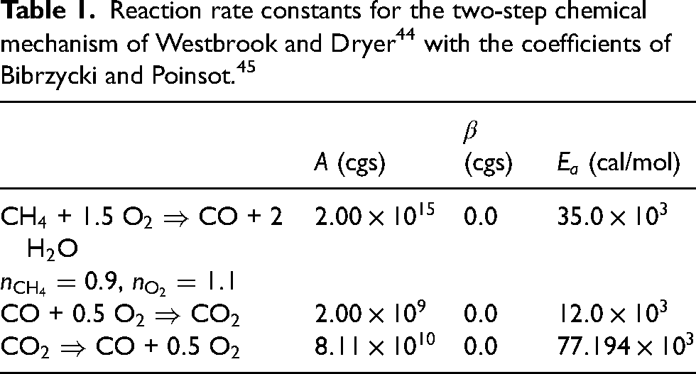
The single-step chemistry used in numerous previous studies of forced ignition of homogeneous and inhomogeneous mixtures46,24,26,25 is unable to account for the effects of CO concentration in the fuel blend on the flame characteristics, and thus a different mechanism has been used here. The two-step chemical mechanism of Westbrook and Dryer44 recently applied in the analysis of the localised forced ignition of turbulent biogas/air mixing layers16 is also considered in the present study. This mechanism accounts for the presence of species (CH, O, CO, CO, HO and N) and represents an intermediate step towards more complex chemistry while remaining affordable. It is listed in the form of three steps as shown in Table 1.
Reaction rate constants for the two-step chemical mechanism of Westbrook and Dryer44 with the coefficients of Bibrzycki and Poinsot.45
(cgs)
(cgs)
(cal/mol)
CH + O CO + HO
,
CO + O CO
CO CO + O
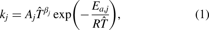
The rate constants are expressed using an Arrhenius law as follows:
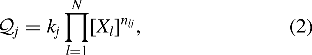
where , and are the pre-exponential constant, temperature exponent and activation energy of reaction ,47 respectively, and is the dimensional temperature. The reaction progress rates are then estimated by
where is the number of species involved in reaction , is the stoichiometric coefficient of species in reaction and is the molar concentration of species . The coefficients retained in this work follow those proposed for the CERFACS 2s_CM2 mechanism48,45 and are detailed in Table 1.
This mechanism accurately estimates the laminar burning velocity of lean CH/CO/air mixtures but fails to do so for fuel-rich mixtures. To improve the accuracy of the mechanism for these mixtures, the pre-exponential adjustment (PEA) proposed by Bibrzycki and Poinsot45 has been retained and tailored such that the laminar burning velocity of rich CH/air mixtures matches closely with the GRI-mech 3.049 predictions.
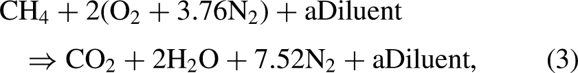
The combustion of CH/CO blends can be represented by the following global stoichiometric equation
where the diluent is CO in this work. Following Galmiche et al.,10 the fuel stream composition is defined using the dilution percentage that represents the molar fraction of CO in the reactants
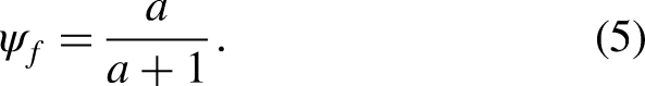
An alternative definition of the fuel stream composition relies on the dilution percentage that represents the molar fraction of the CO in the fuel blend (i.e. CH + CO), such that
Note that only the fuel based definition will be used in this work such that in the reminder of this article.
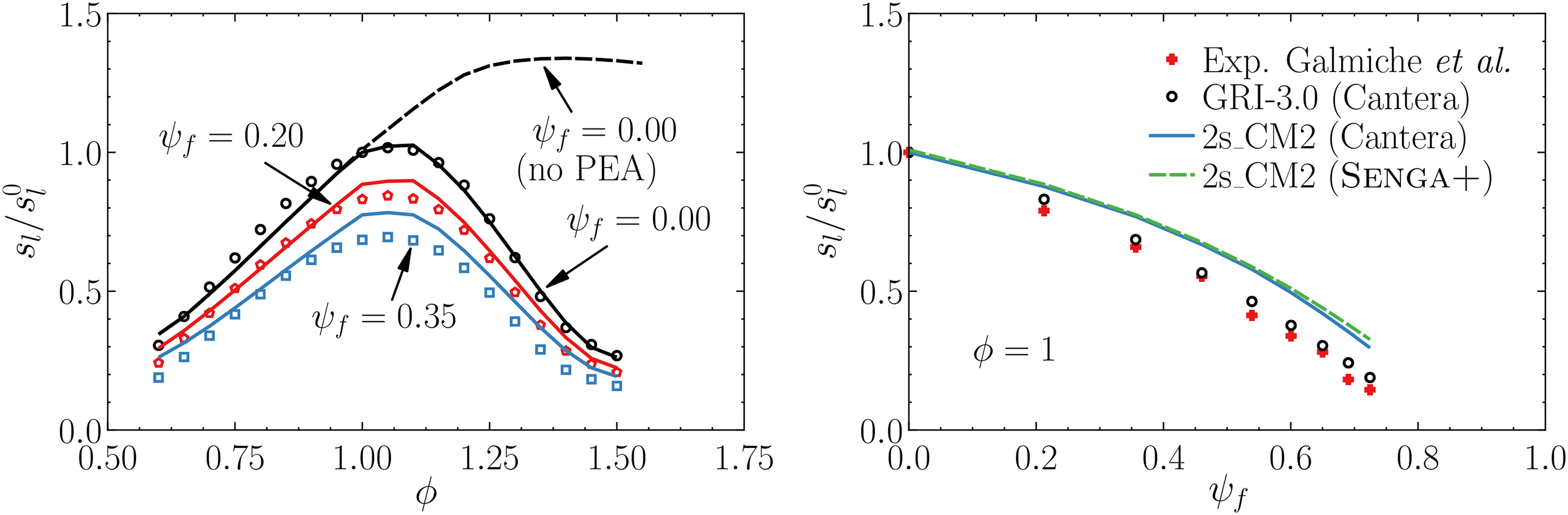
The validation of the chemistry is presented in Figure 1, where the unstrained laminar burning velocity of a CH/CO/air mixture normalised by the laminar burning velocity of a stoichiometric undiluted mixture (i.e. CH–air, ) at different values of the equivalence ratio and dilution parameter is compared with reference results obtained with Cantera50 and the GRI-mech 3.0.49Figure 1 also highlights the effect of the PEA applied for fuel-rich mixtures. Overall, the equivalence ratio dependence of the laminar flame speed is correctly captured across the whole flammability range. However, the flame speed of diluted mixtures is systematically over-estimated by the present mechanism compared to GRI-mech 3.0 or the experimental data of Galmiche et al. 10 and this overestimation increases with . As is overestimated by the 2-step chemistry adopted in the present analysis for , the present analysis has been conducted for .
Laminar burning velocity of CH/CO/air mixtures (left) as a function of and computed with (plain lines) Senga+ using the 2s_CM2 mechanism with PEA and (dashed line) Senga+ using the unmodified 2s_CM2 mechanism (symbols) Cantera using the GRI-mech 3.0 mechanism and (right) for stoichiometric mixtures as a function of .
Following previous numerical investigations of the ignition and flame kernel development in inhomogeneous mixtures,51,24,26,21,22,40 several assumptions are made in this work. All the species are considered as calorically perfect gas with equal heat capacities at constant pressure (). Moreover, the Lewis number of all species is taken to be unity.
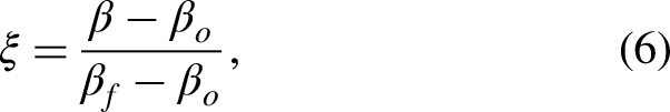
The mixture composition is locally described in terms of the mixture fraction , which is defined following Bilger52 as
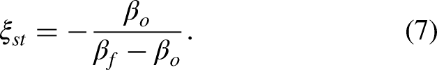
with , and being the values of in the pure oxidiser and fuel streams, respectively, and and denote the atomic mass fractions and weights, respectively. The stoichiometric mixture fraction is thus a function of the fuel blend composition and is given by
It is noted that the current chemistry modelling is not designed to capture quantitatively autoignition, however, it can do so qualitatively. Furthermore, autoignition is not expected to be one of the driving mechanism of the flame kernel growth and potential flame stabilisation. Similarly, the chemical scheme adopted here is expected to capture only qualitatively the occurrence of quenching but quantitative differences with a detailed chemical mechanism are expected. In the case of forced ignition, the temperature attained because of external energy deposition is high enough to result in a very small value of ignition delay time. Therefore, any inaccuracies in the ignition delay prediction do not significantly affect the results presented in this paper because the subsequent flame kernel development is principally determined by flame propagation. Recently, it has been demonstrated by Papapostolou et al.12 that the minimum ignition energy variation with turbulence intensity for the stoichiometric homogeneous mixed biogas–air mixture using this chemical mechanism provides excellent qualitative and quantitative agreements between DNS46,12 and experimental53,54 results. Moreover, the flame structure resulting from localised forced ignition of turbulent gaseous mixing layer and droplet-laden mixtures using single-step Arrhenius-type chemistry24,55,56 are qualitatively similar to those obtained from detailed chemistry simulations.57,58
It was demonstrated by Turquand d’Auzay et al.31 that the edge flame propagation statistics for forced ignition of turbulent mixing layers for the chemical and transport models used in this article have been found to be qualitatively similar to the detailed chemistry DNS studies.59–61 It is worth noting that pioneering analytical studies62–66 on ignition have been conducted for single-step irreversible Arrhenius type chemistry. Furthermore, it has been found that the statistical behaviours of the edge flame displacement speed including its strain rate, curvature, and scalar gradient dependencies from simple single-step chemistry DNS data24,67,40,29,30 have been found to be qualitatively consistent with detailed chemistry DNS59–61 and experimental68 findings. The current analysis adopts a chemical mechanism which is more detailed in comparison to several previous analyses.24,67,40,29,30 Moreover, the seminal DNS analysis on autoignition by Mastorakos et al.69 was conducted in the context of single-step Arrhenius type chemistry, and the findings of that analysis (e.g. negative correlation between reaction rate magnitude and scalar dissipation rate) were subsequently confirmed in detailed chemistry DNS studies.70 However, in the future the results of the current analysis will need to be validated using a more detailed chemical mechanism, which is capable of predicting both ignition delay and flame propagation characteristics accurately.
Finally, despite the assumptions made in this work but thanks to the presence of the reaction in the mechanism,71 the adiabatic temperature of both stoichiometric and off-stoichiometric mixtures corresponds approximately to those of the full GRI-mech 3.0 mechanism. As a result, the expansion of the flow around the flame as well as its effect on the mixing field are expected to be appropriately accounted for.
Ignition modelling
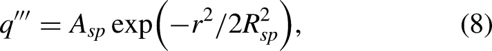
The effects of the localised forced ignition are accounted for by the addition of a source term to the energy conservation equation () taken to follow a Gaussian distribution in the radial direction from the ignition centre65,66,21,23,25,58,72,26,24,46,16 and expressed as
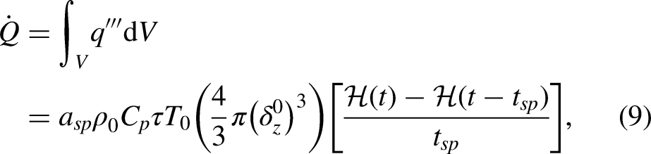
where is the distance from the ignitor centre and is the characteristic width of the energy deposition. The constant is determined by a volume integration leading to the total ignition power given by
where is a parameter determining the total energy deposited by the ignitor,21,23,25,58,72,20,46,16 is the heat release parameter ( and are the reactants and stoichiometric adiabatic undiluted biogas/air flame temperatures, respectively), is the Zel’dovich thickness of the stoichiometric undiluted methane/air premixed flame ( where is the reactants mass diffusivity) and and are Heaviside functions that ensure that the ignitor is only active until . The energy deposition duration is expressed as where is the energy deposition parameter and is a characteristic chemical time scale. The suggested range for optimal duration of energy deposition is .73 For a shorter duration, strong shock waves that dissipate energy can be formed, and for a longer one, the temperature is wastefully dissipated outside of the energy deposition region. The details of the spark formation (momentum modification contribution, plasma and shock wave formation) are not considered in this DNS database for the purposes of simplicity and computational economy.
Edge flame identification, displacement and speed
In previous experimental,32,74,28,75–77 numerical59,70,61,78 and analytical79–84 studies, the formation and propagation of a triple flame structure has been shown to play a significant role in the localised forced ignition of inhomogeneous mixtures. Following previous authors,85,30,29 the edge flame is defined as the intersection of a mixture fraction iso-surface and a fuel mass fraction iso-surface. In this case, the mixture fraction iso-value chosen corresponds to the stoichiometric mixture fraction (, which depends on the fuel blend composition), while the region of the fuel mass fraction isosurface was selected by the zone defined by having a heat release larger than , where is the maximum heat release obtained using a 1D laminar stoichiometric premixed flame having parameters (fuel blend composition, reactant temperature, etc.) similar to the jets considered in this study.
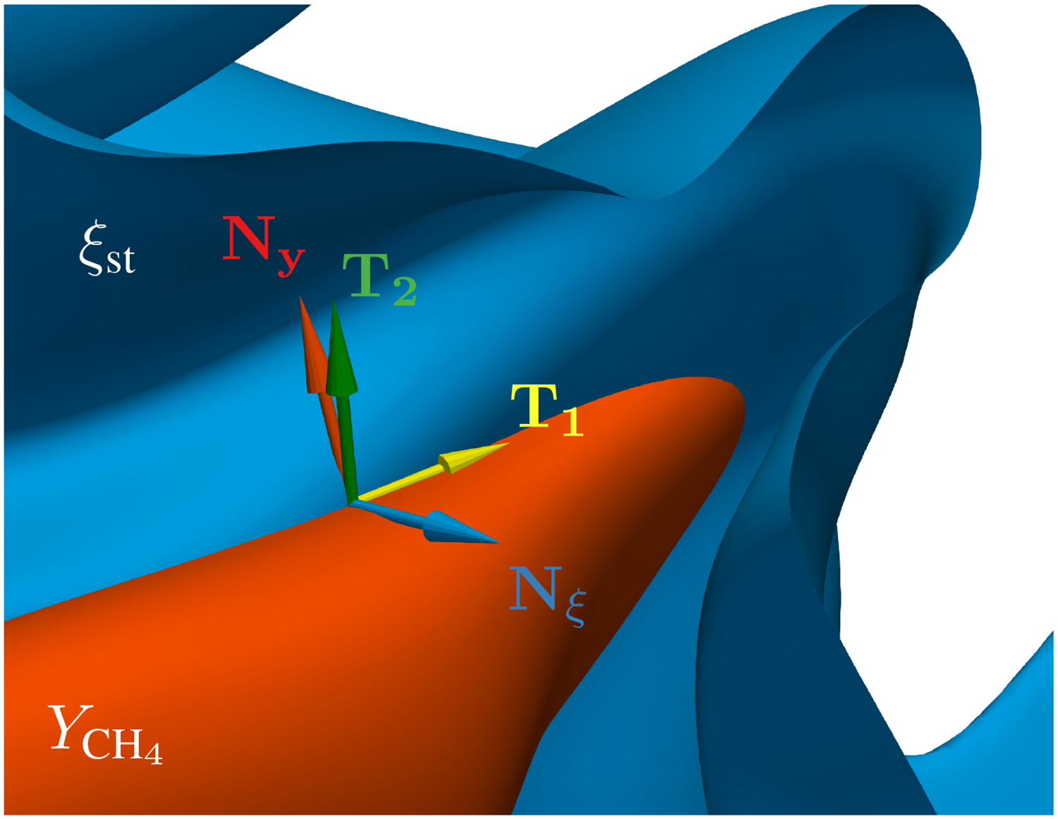
The movement of the intersection depends on a combination of the three following mechanisms: flow velocity (i.e. ), motions relative to the flow of the mixture fraction and fuel mass fraction iso-surfaces (i.e. and , respectively). Following Karami et al.,30,29 a coordinate system moving with the flow velocity is defined as indicated in Figure 2. Two vectors normal to the mixture fraction (, pointing towards the oxidiser) and fuel mass fraction (, pointing towards the reactants) iso-surfaces are defined as
The vector , tangent to both the mixture fraction and fuel mass fraction iso-surfaces is used to define the vector that is both normal to (pointing towards the reactants) and tangent to the mixture fraction iso-surface, as follows
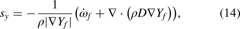
The fuel mass fraction and mixture fraction iso-surfaces move with respective velocities and with respect to the background fluid motion. These velocities are defined following the existing literature67,41,77
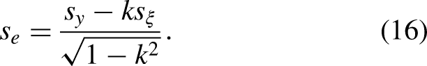
The overall velocity of an edge point on the iso-surface is denoted and can be decomposed into the ortho-normal coordinate system, such that ,29,30 where is the projection of into the plane tangential to the mixture fraction iso-surface. By further defining , and taking the dot product , the edge flame speed is expressed as
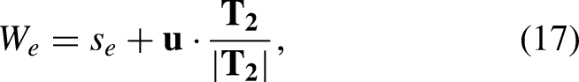
Accounting for the local flow velocity (), the edge flame propagation speed in the laboratory reference frame is
and its streamwise component along is
where is the unit normal vector along pointing downstream.
Example of the coordinate system moving with the flow velocity along the edge flame – (orange) and (blue) iso-surfaces.
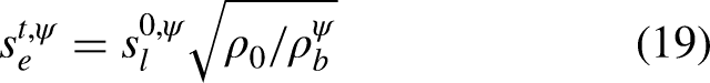
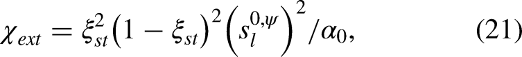
Following Ruetsch et al. 79 and accounting for the CO concentration, the predicted theoretical laminar edge flame speed can be expressed as
where and are the unstrained laminar stoichiometric burning velocity and the burned gas density of the mixture with dilution level , respectively.
Flame diagnostics
Some parameters used for the flame diagnostics that will be used in the remainder of the paper to analyse the flame behaviour are introduced here.
First of all, the scalar dissipation rate (SDR) which measures the rate of molecular mixing has been shown to play a key role in the development of flame kernel16,46 in homogeneous and inhomogeneous mixtures as well as edge flames.24,30,85,83,82It is defined as
In this work, the SDR will be normalised by its extinction value86 which is defined as
where is the reactants thermal diffusivity.
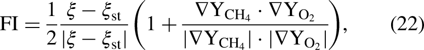
The degree of mixing between the fuel and oxidiser can be measured using the flame index (FI) proposed by Yamashita et al.,87 normalised by Domingo et al.,88,89 Bray et al. 90 and modified by Briones et al. 91 to allow the separation of rich and lean premixed flames, such that
where in region of non-negligible heat release, indicates a non-premixed burning and indicate, respectively, the rich and lean premixed modes of combustion.
Configuration
The simulations have been carried out using the three-dimensional DNS compressible code Senga+92,16,46,67,41 which solves the standard species, momentum and energy transport equations for reactive mixtures. The spatial and time differentiations are carried out using high-order finite difference (th-order central difference for the internal points that reduces to second-order one-sided at the non-periodic boundaries) and third-order low-storage explicit Runge-Kutta schemes.
To reduce the computational cost, a slot jet configuration has been considered in this analysis as opposed to the axisymmetric jet configuration experimentally analysed by Ahmed and Mastorakos.28 However, the values chosen for the main ratios (e.g. the ratio of thermal flame thickness to slot width (or jet diameter, ), the ratio of jet velocity to laminar flame speed () and the ratio of burned to unburned density ()28) are kept as similar as possible. Furthermore, to keep the cost within the available computational time it was not possible to match the jet Reynolds number used in the experiments ().
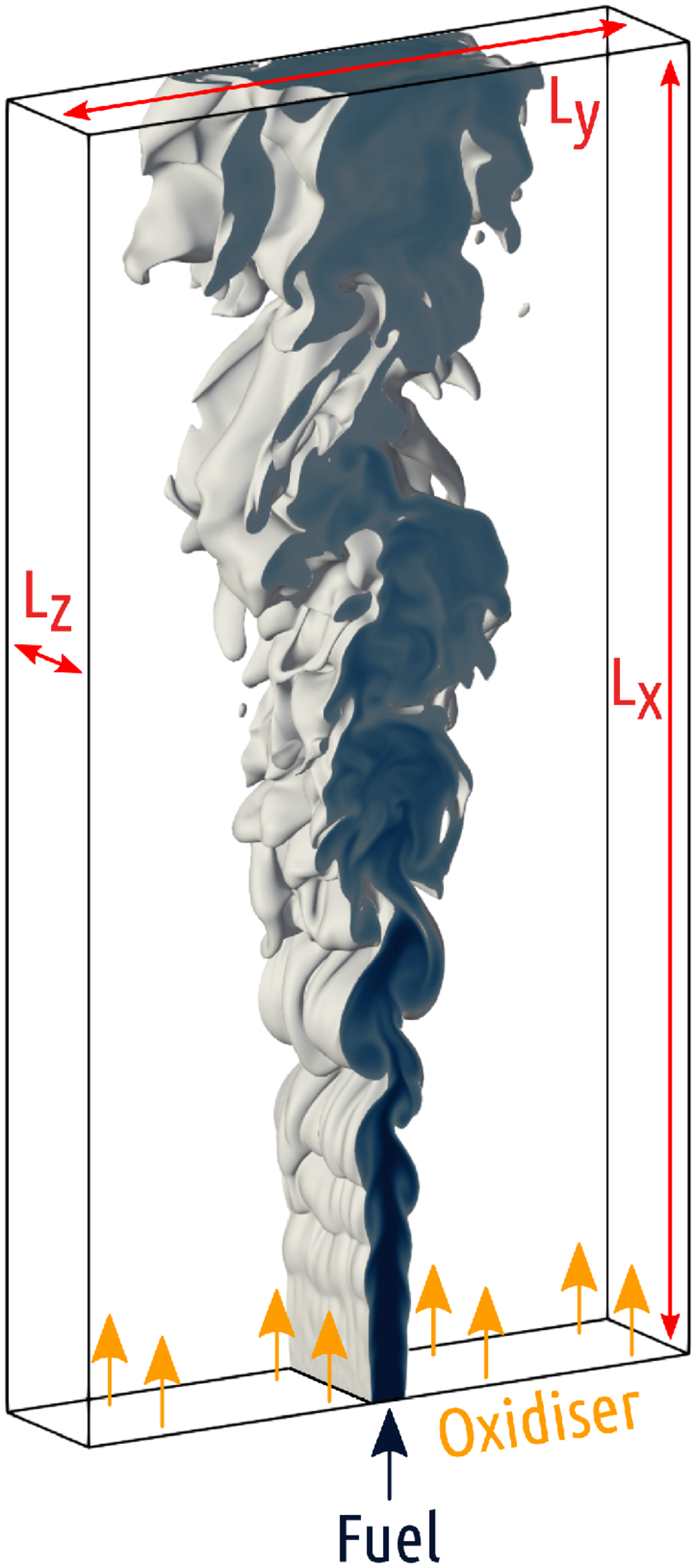
The planar jet simulated here has a slot width of (where is the thermal flame thickness of the stoichiometric laminar undiluted methane/air flame, with , and being the adiabatic flame temperature of the undiluted stoichiometric methane/air mixture, instantaneous dimensional temperature and unburned gas temperature, respectively). The computational domain is long and wide enough to accommodate both the non-reacting and reacting flow developments with dimensions and is shown in Figure 3.
Flow configuration schematic.
An extensive parametric analysis in terms of spatial location of the ignitor centre and the mixture composition at the ignitor location for different CO blends has been conducted, of which only a subset is considered here, thus some compromise have been made to limit the computational cost. For example, periodic boundary conditions have been used in the transverse direction due to the much longer domain and flow-through time than those considered in other similar analyses reported in the literature.30,29,67,93,94A partially non-reflecting outflow was applied in the streamwise direction using the Navier-Stokes characteristic boundary conditions method.
Note that, given the periodicity and confinement in the spanwise direction, the configuration is more akin to an infinite row of jets in the spanwise direction. It has been demonstrated elsewhere31 that the non-reacting flow statistics in terms of mean and root-mean-square (rms) values of mixture fraction and axial velocity indicate a fully developed flow regime starting around (where ) up to , where confinement effects begin to manifest. However, this confinement does not manifest in the velocity and mixing profiles below .31 It has been shown in the Supplemental Material of Turquand d’Auzay and Chakraborty31 that the mean velocity, jet width and turbulent velocity fluctuation statistics in non-reacting jet matches well with self-similar solutions and experimental findings,95 which inspires confidence in the fidelity of these simulations.
The domain is discretised using a uniform Cartesian grid of cells thus ensuring cells across the jet width and at least seven grid points within . This also ensures that the Kolmogorov length scale is equivalent to grid spacings at the nozzle lip.
A fuel/air mixture is injected through the slot with a bulk mean velocity and issues in a coflow of pure air with a velocity of . This yields a jet Reynolds number of . The coflow is assumed to be laminar without any velocity fluctuations, whereas the velocity fluctuations at the slot inlet are imposed by scanning a plane through a frozen periodic turbulent channel flow solution with a scanning velocity . It is worth noting that the fluctuating velocities of the channel flow corresponding to a frictional Reynolds number are scaled with respect to the mean bulk velocity and these scaled fluctuations are used the inflow. The choice of for the turbulent inflow specification is motivated by the fact that profiles of turbulent velocity fluctuations normalised by bulk mean velocity reach self-similar pattern for . It is important to appreciate that there is a degree of numerical assumption involved in the specification of turbulent inflow. A fully developed channel flow solution profile is used here to specify realistic velocity fluctuations at the inlet rather than specifying artificial noise, digital filtering method or scanning a plane through homogeneous isotropic turbulence. All of the above methods involve some degree of arbitrariness, and the approach adopted in this paper is probably less arbitrary in comparison to the other alternative methodologies because the length scale and turbulent velocity fluctuations are representative of a fully developed channel flow. Moreover, the flame development following localised ignition takes place sufficiently away from the inlet and thus the inflow turbulent boundary condition does not affect the flame dynamics presented here.
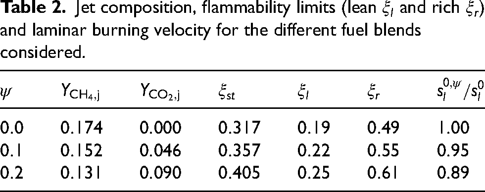
The oxidiser mass fraction in air (coflow) is , while the mixture injected through the slot is composed of of CH/CO blend and of air per volume. Three different CH/CO blends are considered in this analysis with varying between and , where the upper limit is chosen based on experimental observations made on a replica of the Cambridge burner used in28 reporting that for no flame stabilisation was possible.96 It was further reported that for such dilution levels, obtaining a kernel required a very large energy input and that the flame kernels thus obtained were not necessarily self-sustained once the spark was switched off.96 The values of flame speed, , and corresponding to the different fuel mixtures investigated are summarised in Table 2.
Jet composition, flammability limits (lean and rich ) and laminar burning velocity for the different fuel blends considered.
Both the jet and the coflow temperatures are taken to be K yielding a heat release parameter of . Standard values have been chosen for the Prandtl number () and the ratio of specific heats ().
A precursor non-reacting flow DNS has been conducted for about two flow-through times (where ) such that the initial transients disappear and that realistic fluctuations of both the mixture composition and velocity fields are obtained. This field is taken to be the initial condition for the reacting flow simulations.
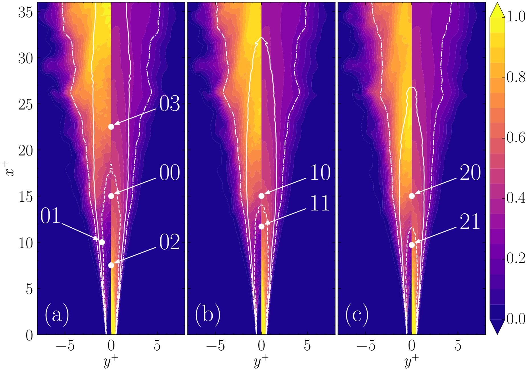
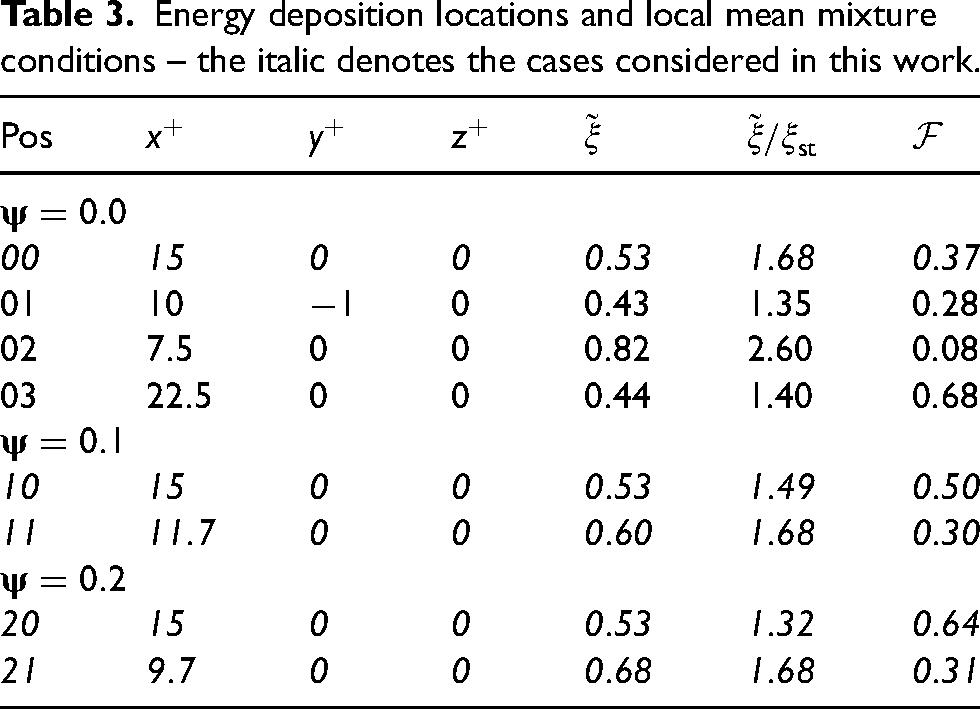
The ignitor energy, deposition duration and characteristic width are kept constant throughout this study and comparable to previous work16,46,31,24,40 with , and . Different locations have been simulated as shown in Figure 4 along with the distributions of mean mixture fraction () and flammability factor (). The flammability factor is defined by Birch et al. 27 as the probability of finding a flammable mixture at a given point and measured as (where is the probability density function of the mixture fraction extracted from the non-reacting DNS data). The normalised coordinates of the ignitor centre along with , and values are summarised for the different locations in Table 3. It can be seen from Table 3 that the spatial location of the ignitor centre has been modified which gives rise to the variations of the Favre-averaged mixture fraction value and flammability factor at the ignitor location. This means altogether eight different cases have been simulated and the simulations , and have been discussed elsewhere31 and are not discussed in this article. The current work only considers a subset composed of the cases , , , and , while the interested reader is directed to the previous work by Turquand dAuzay and Chakraborty31 for details on the spark location effects on the probability of successful ignition and subsequent flame development.
(Left panel) flammability factor () and (right panel) mean mixture fraction () for (a) , (b) and (c) – (plain line) , (dashed line) and (dash-dotted line) – the white dots denote the energy deposition locations.
Energy deposition locations and local mean mixture conditions – the italic denotes the cases considered in this work.
Pos
Looking at the cases , and (ignitor on the jet centreline at ), it can be seen that an increase of the CO content in the fuel blend leads to a corresponding increase of the value of and brings closer to suggesting that more favourable ignition conditions are found. By contrast, it appears necessary to move the ignitor closer to the nozzle to maintain a constant value of as increases, which could detrimentally affect the ignition due to larger velocity and scalar gradients amongst others.
The reacting flow simulations are run for about which also corresponds to , where .
Results and discussion
Flame development
Using the selected deposited energy, a successful thermal runaway (the maximum temperature value either reaches or exceeds the adiabatic flame temperature during or shortly after the energy duration deposition period) is observed at all ignitor locations from Table 3 considered in this study. This constitutes the kernel establishment phase of the flame kernel development following the nomenclature outlined by Mastorakos.1,2 Additionally, for all these cases, a successful self-sustained growth of the kernel (i.e. without the assistance of the external energy deposition) is observed followed by indications of flame stabilisation.
It is worth noting that the outcome of the local energy deposition is highly stochastic in nature, but this aspect is not detailed further here since it was addressed in detail in31 for the cases with , and a qualitative alteration is not expected with CO concentration in the fuel blend, even though the resulting ignition probability maps will be different.
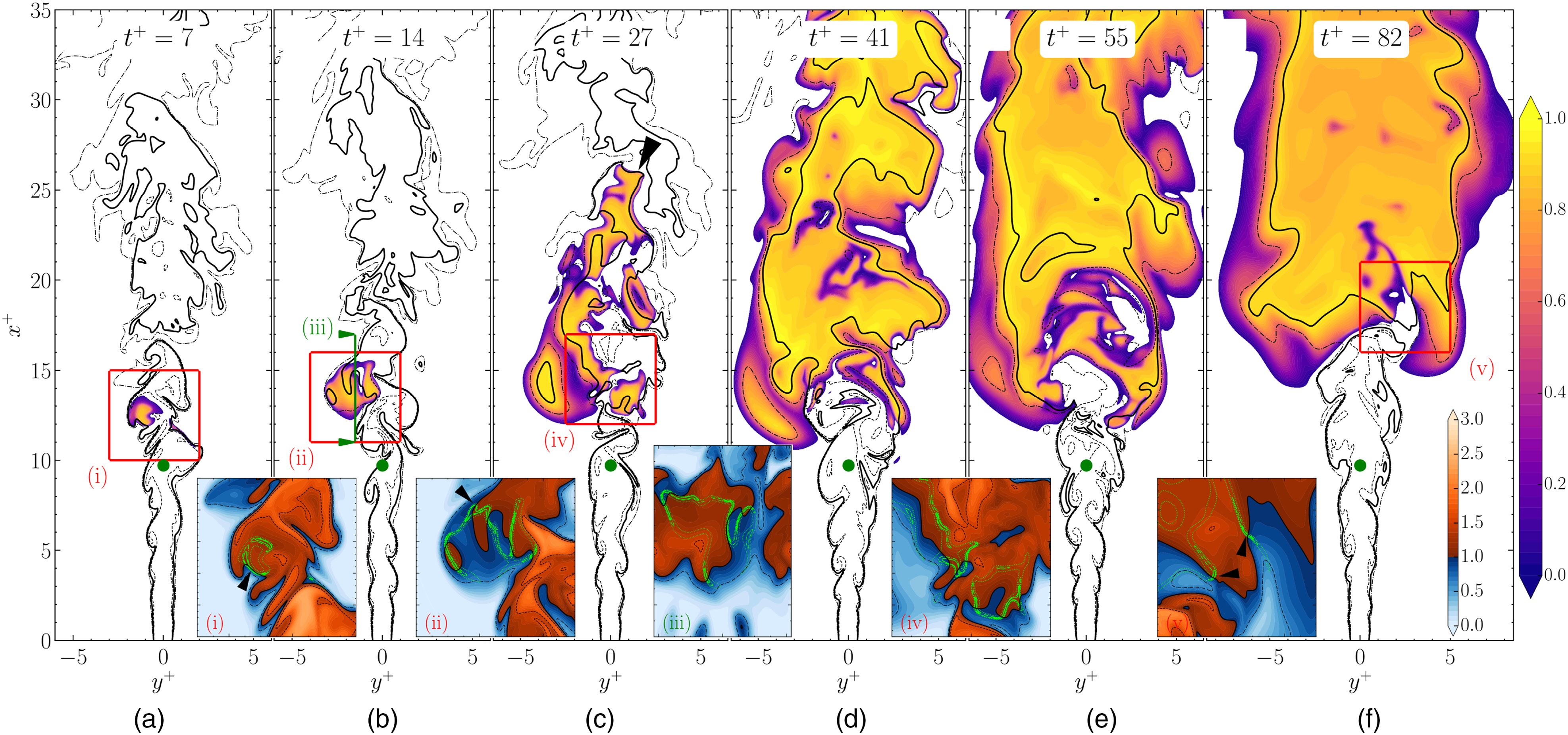
The temporal evolution of the non-dimensional temperature field in a – plane is shown in Figure 5 at different times for the ignitor position . The behaviour presented here has been found qualitatively similar for all the other cases, i.e. the different stages of the flame development that are (i) initial kernel formation, (ii) kernel downstream advection and radial/transverse growth, (iii) upstream flame propagation, described experimentally28 and in LES studies,35,36,34,38 are also observed here.
Time evolution of the non-dimensional temperature in a plane for the ignitor position overlaid with black mixture fraction iso-lines (plain: , dashed: and dash-dotted: ) – insets (i)–(v) show the field overlaid with similar black iso-lines for the normalised mixture fraction and green iso-lines corresponding to %, % and % of in the plane for (i)-(ii) and (iv)-(v) and plane for (iii) – the green dot marks the energy deposition location – the black arrowheads highlight some edge flames.
In Figure 5, mixture fraction iso-lines for , and are superimposed onto the temperature field. Insets present the field of overlaid with green lines indicating , and of the maximum heat release rate () of the unstretched laminar premixed stoichiometric flame with dilution .
The high-temperature kernel resulting from the thermal runaway remains roughly spherical during the initial flame establishment stage, for a duration that depends on the local conditions. Due to the higher turbulence levels found at the energy deposition location, the kernel loses its sphericity after roughly for the cases and , and retains it up to for the cases and with an energy deposition at . The hot gas kernel is advected downstream (compare its most upstream position between Figure 5(a) and (b) and the energy deposition position) while the flame grows in the spanwise direction (i.e. ).
From , a triple-flame structure develops around the iso-surface in the shear layer (see black arrow in inset (i)). Subsequently, the volume of the kernel increases rapidly thanks to the downstream edge flame propagation supported by the large velocity magnitude at the jet core (see edge flame in inset (ii) and in Figure 5(c)). Turbulent flow-induced advection along with moderate values of and the availability of flammable mixture gives rise to the growth of the hot gas region in the transverse direction (see inset (iii)) that eventually spans over the whole width of the jet for . Consequently, a second triple-flame structure forms along the mixing layer (inset (iv)) while several other similar structures become apparent as the flame development progresses and the flame sheet spans the whole jet width.
The third stage of the ignition process in jet (i.e. ) relies heavily on edge flames that propagate within the flammability limits. The propensity of finding and flammable mixtures (i.e. ) increases with CO concentration in the fuel blend for a given axial location of the energy deposition (up to ), but in the case of location (where the local was kept similar to ), this also comes at the cost of significantly higher scalar and velocity fluctuations. Downstream of the reactive layer spanning across the jet, turbulence decays rapidly due to heat release while the jet spreads (e.g. from at to at ) as a result of thermal expansion. Flow acceleration resulting from the thermal expansion is particularly visible between and in the fast counter-clockwise rotation of a large pocket of hot gases moving upstream against the slower moving coflow in the left shear layer. Large pockets of unburned mixture can still be found downstream of the flame base (e.g. Figure 5(e)) as the fuel-rich jet turbulent core mixes with either the surrounding fresh air or the hot oxygen-rich products resulting from lean combustion. This pocket penetration phenomenon reduces considerably as increases as the mean equivalence ratio becomes lower for a given axial position (see Figure 4). For all cases, the flame base starts to exhibit indications of stabilisation around driven by the edge flames finding favourable conditions to propagate upstream (inset (v)) up to a point where a balance between their local propagation speed and the downstream fluid motion may be found.
Flame propagation behaviour
Due to the major contribution of edge flame propagation on the kernel development and the kernel-to-flame transition, more discussion is warranted regarding its behaviour. During the kernel expansion (e.g. up to ), regions of high heat release are mostly found around the low regions in the vicinity of . The flame sheet expands into both fuel-lean and fuel-rich mixtures, but upon finding too lean regions (i.e. ) local extinctions can be observed. At later times the edge flame structures are found to be sustained even for high values of at which point, consistent with previous findings,17,16,24 the lean premixed branch collapses onto the diffusion branch under high magnitudes of mixture fraction gradient. Under this condition, the premixed branches tend to disappear and a single branch at around is obtained. In this case, a rich premixed branch may still be observed, while the lean branch collapses completely.
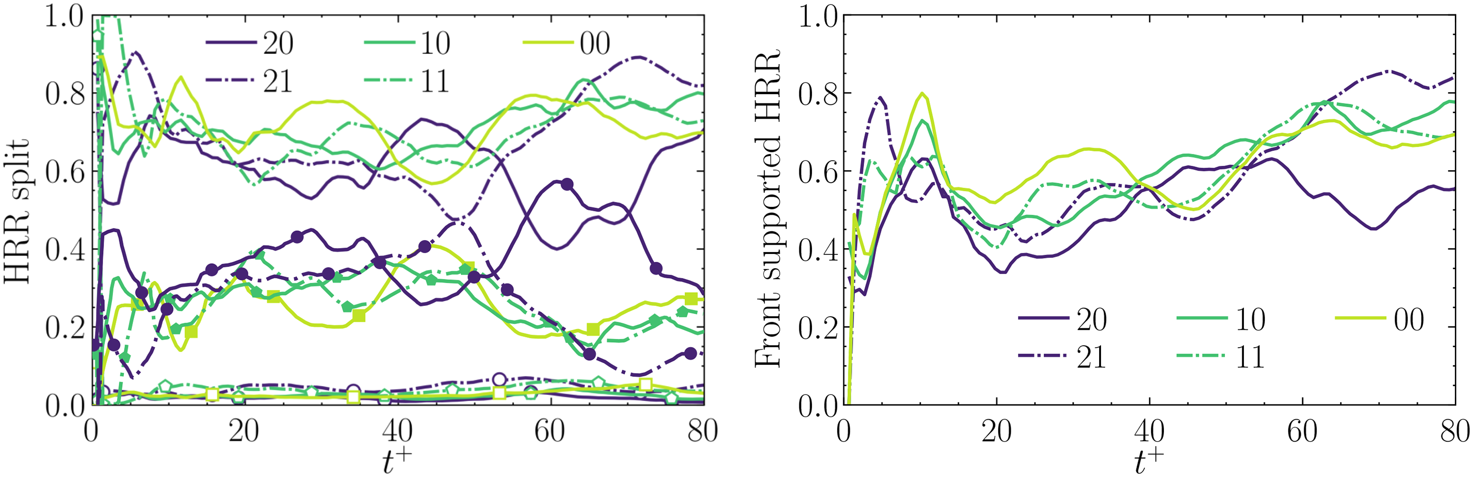
This is further shown in Figure 6 that presents the respective heat release rate contribution of each branch of the triple flame (i.e. conditional integration of heat release rate conditioned on the flame index values corresponding rich- and lean-premixed and diffusion combustion modes) over the flame evolution. At every stage, except for during the early stage, the rich premixed branch is responsible for the major part of the heat release, with the lean branch contribution being lower but non negligible. On the other hand, the heat release due to the diffusion branch remains negligible with less than % on average. The CO concentration in the fuel stream does not seem to affect this balance, although at late time, the rich premixed branch contribution slightly increases with increasing . This seems to appear as a consequence of the upward movement of the flame base towards regions where a much wider fuel-rich core surrounded by the shear layers, in which the flames are stabilised, may be found. Thus, with increasing distance from the nozzle, more flame surface can be found within the jet core compared to the surface existing on the lean side of the mixing layers, explaining the growing imbalance of heat release between the lean and rich branches of the triple flames.
Temporal evolution of (left) heat release rate contribution of (unfilled symbols) non-premixed, (filled symbols) lean and (lines without symbols) rich premixed flame branches and (right) percentage flame elements (selected by ) propagating into richer mixture (front-supported).
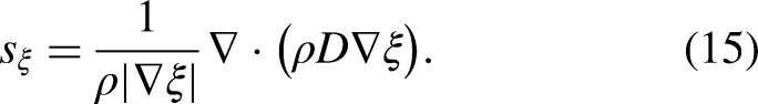
It is also important to understand how the kernel expands within the stratified mixture, which can be achieved by analysing the relative alignment of the mixture fraction and progress variable iso-surface normals, quantified through the angle between and ,
where the progress variable is defined based on the oxidiser mass fraction as
A distinction may be drawn between flame elements propagating towards leaner mixture, usually referred to as back-supported flames (i.e. ), and those propagating towards richer mixture or front-supported (i.e. ). Figure 6(b) also presents the temporal evolution of the percentage of flame elements (selected by ) being front supported for the different energy deposition locations and dilution parameter values. This is consistent with the observations made from Figure 5 for case 21, which shows that the flame expands into the fuel-rich zone as the time progresses from the initial hot gas kernel phase and the results shown in Figure 6(a) and (b) reveal that the same qualitative behaviour has been observed in other cases considered here. Moreover, the predominant heat release rate in the rich premixed mode (see Figure 6(a)) is also a consequence of dominant heat release contribution arising from front-supported flame propagation (see Figure 6(b)). The observations made from Figure 6(a) and (b) further reveal that the level of CO concentration in the fuel blend does not significantly affect the qualitative nature of initial flame development following successful localised forced ignition.
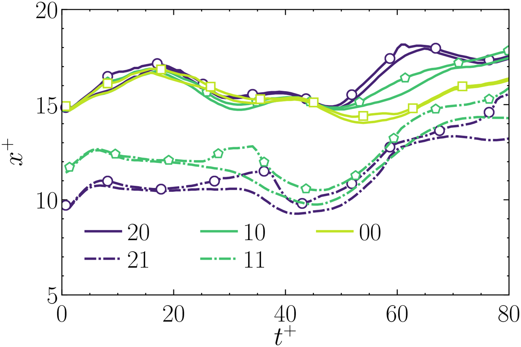
Evolution of the flame height
The temporal evolutions of the flame base height, measured by the lower axial position at which or are shown in Figure 7. It can be seen from Figure 7 that the evolutions are qualitatively similar for all cases considered here, which is consistent with previous findings31,97,36,34,38 for self-sustained flame propagating following ignition at the jet centreline. It can be seen from Figure 7 that the upstream edge is advected downstream following the end of the energy deposition, which is consistent with the observations of Figure 5, and the extent of the downstream advection is dependent on the local flow velocity and mixture composition. Indeed, between and , it can be seen that the speed at which the kernel moved downstream increases while the energy deposition gets closer to the nozzle and encounter larger mean streamwise velocities. Once the edge flame structure is fully established, the flame edge starts to propagate upstream and this appears to happen sooner ( against ) as the energy deposition is closer to the nozzle, which could be linked with the larger mixture fraction intermittency that allows for the flame to encounter more easily a locally stoichiometric mixture. The time to establish the edge flame structure also appears independent of the amount of CO, as can be observed by comparing energy deposition , and . This marks the onset of the third phase of flame development, as reported earlier in experimental28 and numerical studies.97,36,34,38 The duration of this phase depends on the local conditions but also on the and values at the ignitor location. The flame base may move further downstream due to low-frequency oscillations as shown in Figure 7 for the cases , and between to . This movement is controlled by the edge flame propagation statistics in response to the large scale unsteady motion and subsequent propagation or extinction into unfavourable conditions such as regions with equivalence ratio outside the flammability range or high values of .
Temporal evolution of the flame base height based on two different criteria (lines) and (symbols) for the different ignition cases.
Both way of measuring the flame base height may lead to slightly different estimations, as temperature can be advected upstream by low-frequency large scale motions that may be amplified by heat release effects and this can happen irrespective of the local mixture composition. On the other hand, when the flame height is measured using the heat release metric, it may change rapidly due to local extinctions and its evolution becomes temporarily uncoupled from the temperature field. This effect may be seen at for case in Figure 7, and in more details in Figure 5(b) to (d). Similar decoupling happens for case between , and for both and for .
It can further be seen from Figure 7 that the distance between the flame base and the jet inlet increases monotonically for an increase in , when the ignitor is physically placed at the same spatial location. This is attributed to the lower flame speed of the stoichiometric diluted mixture, which directly affects the resulting edge flame speed (see equation (19)) and the height at which an equilibrium can be found between the flame and flow movements in a mean sense as detailed below. In particular, the onset of stabilisation was reported by Turquand dAuzay and Chakraborty31 for the undiluted mixture, but a clear indication of flame stabilisation cannot be ascertained for the cases with and . This also suggests that the probability of obtaining flame stabilisation for CH/CO jet flames is likely smaller than that in the case of undiluted methane-air jets.
Edge flame propagation
In the present analysis, the statistics of the edge flame elements propagating upstream are of relevance from the point of view of kernel growth and the onset of flame stabilisation.31 The corresponding edge flame elements are selected using the value of the fuel mass fraction iso-surface normal projection on the streamwise direction axis (x), that is, (where is the x-component of ). The mean values conditional upon the flame elements characterised by are denoted by and are referred to as upstream facing edge flames.
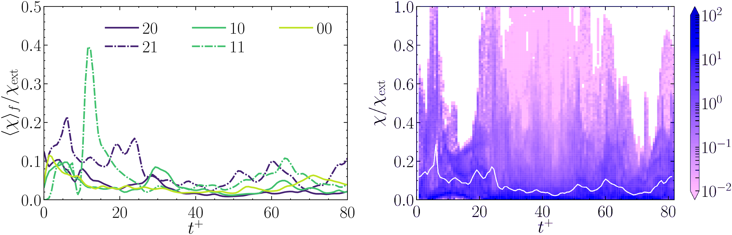
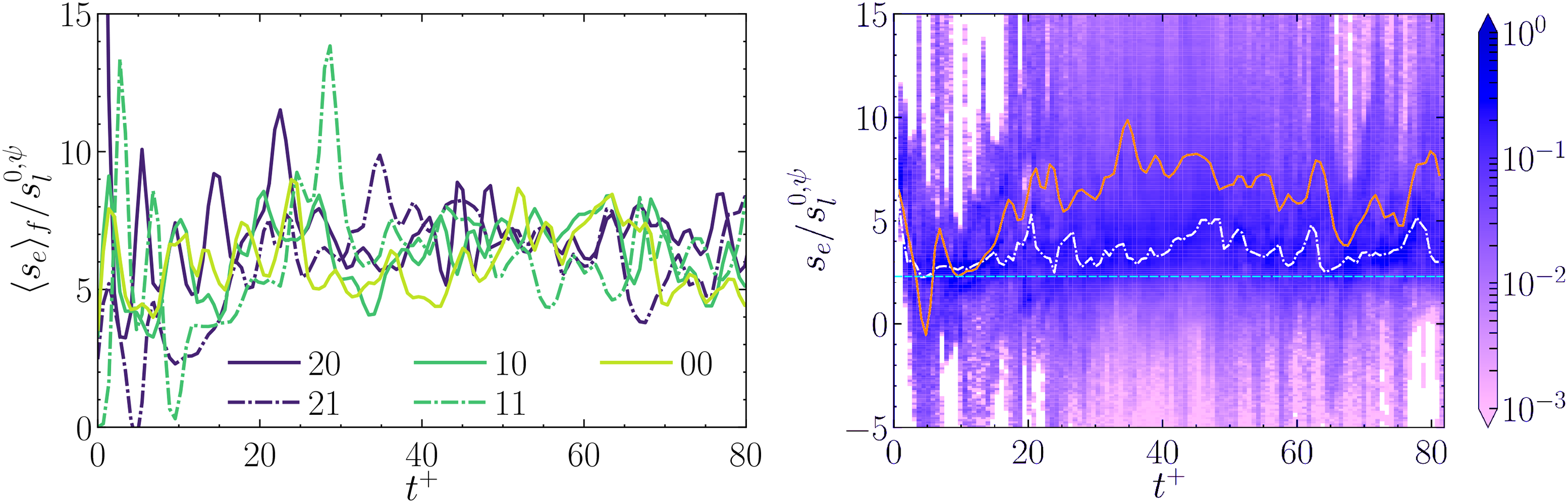
It is well known that the mixture fraction scalar dissipation rate ( or SDR) influences the edge flame propagation rate.30,29,93,24,85,82,83 Therefore, the temporal evolutions of the mean SDR conditional upon normalised by its extinction value (i.e. ) are shown in Figure 8(a) for the different CH/CO/air mixtures injected while the temporal evolution of the normalised SDR PDF of case is exemplarily shown in Figure 8(b) and is qualitatively similar to the other cases. The purpose of the background colour in Figure 8 and subsequent figures indicate the frequency of samples and scatter around the mean value. It can be seen from Figure 8(a) that the magnitude of at a given time instant remains comparable for different values of and that the temporal evolution of the normalised mean value is not significantly affected by the CO concentration in the fuel blend, even though a slight increase of can be seen with an increase in . The local conditions of mixture fraction and its gradient induced by the realisation of the turbulent mixing rate and turbulent strain rate can lead to significantly different values of between different cases at early times but the values of relax to comparable magnitudes at later times. Furthermore, remains smaller than unity throughout the flame evolution which suggests that flame extinction due to high scalar dissipation rates are unlikely in the conditions considered here. By comparing Figure 8(a) with Figure 7, it can be remarked that the upstream movement of the flame base that occurs after the initial downstream advection starts when reaches low values (i.e. ) independent of the value. From then, the mean levels of normalised scalar dissipation rate observed at the flame base remain low and roughly constant which allow for its upstream propagation during the third stage of ignition31 apart from the occasional fluctuations due to the large scale unsteadiness. Figure 8(b) indicates that even though the mean level of normalised SDR remains mostly moderate during the flame evolution, local non-uniformities can be observed along the upstream propagating elements for all CO concentration levels considered. At early times (), large variations are observed between the flame elements during the kernel growth, with local values of larger than unity indicative of local extinctions leading to the formation of some of the holes in the reacting sheet93,85,98 that can be observed from the volume rendering animations. Past , when the edge flames are well anchored in the shear layers, the local variations are much smaller and most of the flame elements propagate in region with moderate values of the normalised SDR.
Temporal evolution of (left) the mean normalised scalar dissipation rate for the different ignition cases (right) the normalised scalar dissipation rate PDF for the ignition case , where the (while solid) line denotes – statistics measured on the upstream facing edge flames elements ().
The temporal variations of the edge flame speed value conditioned on the upstream facing elements normalised by the laminar freely propagating burning velocity at the corresponding CO concentration in the fuel blend (i.e. ) are presented in Figure 9(a) for the different ignition locations and CO concentration levels considered. After the initial transients, the values of oscillate around a mean value of about , whereas the theoretical laminar edge flame speed is about (i.e. ) for all cases, leading to . Despite moderate values of Reynolds number, the edge flame speed shows a significant amount of scatter around the most probable value. It can be seen from Figure 9(b) that the edge flame speed shows a significant scatter around the expected laminar value. This scatter is contributed by the strain rate, curvature and scalar dissipation rate fluctuations induced by turbulent motion. This can further be substantiated by the fluctuation of the scalar dissipation rate around its mean value in Figure 8. The integral effect of turbulence is manifested in the much higher value of than the theoretical laminar edge flame speed (i.e. ). As the edge flame propagation plays a key role in flame stabilisation, the flame evolution following thermal runaway in the cases studied in this paper is considerably different from laminar conditions despite moderate values of Reynolds number of the simulations. The edge flame values shown in Figure 9(a) and (b) correspond to a fluctuation of around in this configuration or , indicating that the magnitude of the flame base propagation rate can be significantly larger than the coflow velocity. Thus, the flame orientation (propagation along ) may play a key role in the anchoring of the flame base wherever a local equilibrium is obtained between the flow velocity and the edge flame speed. The high mean values of occur due to the local non-linear stretch rate and scalar gradient dependencies of the edge flame speed, which have been demonstrated and discussed extensively elsewhere41,85,30,29,67,77,83,82,17,60,61 for canonical configurations and similar qualitative trends has been observed here but will not be discussed further for the sake of brevity. Figure 9(b) shows the temporal evolution of the normalised edge flame speed PDF of case . The most probable value of at any point in time remains close to the theoretical prediction, while the probability of finding negative value is mostly negligible with small fluctuations. These are indicative of the flame locally reaching unfavourable areas mostly characterised by high SDR values. On the other hand, the probability of finding edge flame speed larger than the theoretical estimate remains non negligible up to as previously observed by Heeger et al.68 The fuel blend composition as well as the ignition location have only a marginal effect on the temporal evolution of the PDF, but noticeably, the probability of finding negative values of increases with increasing and decreasing distance from the nozzle (i.e. increasing mean SDR). This is mostly visible at very early times here (i.e. ) where the probability of having a negative edge flame speed is dominant before decreasing as the flame base height increases.
Temporal evolution of (left) the mean normalised edge flame speed for the different ignition cases (right) the normalised edge flame speed PDF for the ignition case , where the (solid orange) line denotes , the (chain-dotted white) line denotes the maximum value of the PDF and the (cyan dashed) line denotes – statistics measured on the upstream facing edge flames elements ().
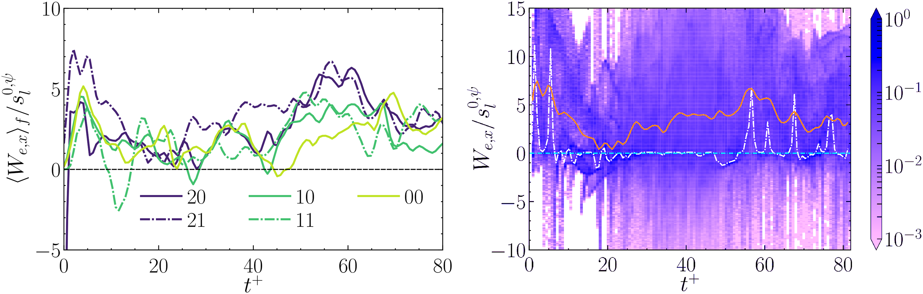
The propensity of the edge flame to propagate upstream is demonstrated in Figure 10(a) through the temporal evolution of the normalised mean edge flame propagation speed streamwise component (i.e. ) measured along the upstream facing flame elements (i.e. ). A positive value of denotes a downstream movement of the flame elements and vice versa. The large positive values of observed during the initial phase (e.g. ) for all cases is indicative of the rapid kernel downstream advection (first development phase of the kernel to flame transition) and is the highest for case , where the ignitor is the closest from the nozzle, and thus where the mean streamwise velocity is the highest. The positive value of then starts to decrease (e.g. ) when the edge flame structure is established. Over the interval , the flame propagation velocity decreases down to almost zero suggesting a local equilibrium between the edge flame movement and the local flow field in a mean sense. Following that, stabilises to comparable small positive values during as the flame base height continues to decrease for the cases , and (see Figure 7). Finally, starts to increase again for which is consistent with the increase in flame base height with time (see Figure 7) and this increase is more pronounced for higher values of . A comparison between Figure 9(a) and Figure 10(a) reveals that (this is also valid for because is a constant multiplier of ) does not change significantly over the duration where increases rapidly. This implies that the upstream propagation of the mean flame base (small or negative values of ) needs the local flame orientation (and thus ) to have a large negative streamwise component. This would correspond to the edge flame being at 3 o’clock following the notation introduced by Karami et al.,30 or at the outer-most point of the large eddy where the flame net motion is upstream and inwards, which also correlated with Figure 6 where there are indications of a net motion towards richer mixtures. Finally, the evolution of exhibits another period of decay, which can be associated with large scale fluctuations of the flame base height but can also be attributed to turbulence decay as the mean axial velocity decreases considerably () by the height where the onset of flame stabilisation eventually starts (e.g. for ). As decreases with increasing , the local equilibrium between the fluid velocity and the streamwise edge flame speed component is likely to occur at an increasing height from the nozzle, and the flame stabilises further away from the jet inlet for an increase in CO concentration in the fuel blend. By looking further at Figure 10(b) which exhibits the temporal evolution of PDF, one may remark that even if the mean value is positive at almost all time for the different cases, local regions of the PDF show a high probability of finding a null or slightly negative value of indicating the flame elements can locally propagate upstream, on which the flame base depends to stabilise, while the majority of the other elements do not contribute to the stabilisation.
Temporal evolution of (left) the mean normalised edge flame propagation speed for the different ignition cases (right) the normalised edge flame propagation speed PDF for the ignition case , where the (solid orange) line denotes , the (chain-dotted white) line denotes the maximum value of the PDF and the (cyan dashed) line denotes – statistics measured on the upstream facing edge flames elements ().
Summary and concluding remarks
The localised forced ignition and subsequent flame propagation of a turbulent CH/CO jet issuing in ambient air have been analysed using DNSs. A simplified two-step chemical mechanism has been considered to account for the CO blending effects on the flame speed and temperature, while retaining sufficient accuracy for the present range of operating conditions. Three different CO concentration levels ranging from % (i.e. pure CH fuel composition) to % have been considered while the energy deposition characteristics (energy, radius, duration) remain unchanged. To investigate the effect of CO concentration on the jet ignition success, five different energy deposition scenarios have been considered, three cases where the mean mixture composition at the ignitor varies, but not its location in space, and two other where the mean mixture composition within the energy deposition region remains constant, but where its spatial location varies with CO concentration in the fuel blend. The effects of CO concentration in the fuel blend on the mean field have been reported, and it was shown that the addition of CO would lead the most favourable region (from the flammability factor standpoint) for the flame development to be displaced closer to the nozzle. However, moving the ignitor closer to the nozzle could detrimentally affect the ignition due to the larger velocity and scalar gradients encountered locally.
The temporal evolution of the kernel to flame development was found to follow the experimentally reported behaviour with the three stages of development qualitatively reproduced here, from the kernel initial growth and its downstream advection by the mean flow field to the final upstream propagation and onset of stabilisation through the radial expansion and downstream propagation stage. The qualitative evolution was found to be insensitive to CO concentration in the fuel blend (within the range investigated), although it must be noted that a large energy input has been used. Irrespective of the CO level concentration in the fuel blend, and similarly to our previous work,31 the flame base dynamics was shown to be governed by edge flame propagation in the two shear layers found on either side of the nozzle, while its propensity to stabilise was dictated by the ability of the edge flame to locally propagate faster than the flow field. The effects of CO concentration on the flame lift-off become noticeable only a long time after the ignition, when both the edge flame structures and the reacting front spanning the jet width are well established. From this point onward, the lift-off height increases monotonically with the CO levels which is attributed in particular to the lower flame speed of the diluted stoichiometric mixture, while the probability of obtaining flame stabilisation for the cases with and appears smaller than that in the case of undiluted mixture.
The heat release contributions to the overall heat release of the different branches of these triple flame revealed that the non-premixed branch contribution is negligible with less than % of the total heat release on average, while the rich-premixed branch contributes the most with a contribution of at least % and no effect from the CO content was found on these.
Lastly, the edge flame statistics were investigated for the different scenarios, with a focus on the edge flame elements being orientated towards the jet, that is upstream facing. An increase in CO concentration in the fuel blend leads to small albeit noticeable increase of the mean normalised (by its extinction value) scalar dissipation rate experienced by the edge flame, although the long term averaged value stabilises well below the extinction value with low frequency oscillations driven by the large scale motions. After the initial kernel growth driven by the large temperatures resulting from the energy deposition, it was found that the mean edge flame speed oscillates around a value which is larger than the coflow velocity with and non-negligible with respect to the jet velocity with . It was further shown that the orientation of the local fuel mass fraction normal plays a significant role in the stabilisation of the flame by controlling the direction in which it propagates, that is, when it displays a large negative streamwise component, the flame is able to locally propagate upstream. The mean value of appears only marginally affected by the CO concentration, although it was found that the probability of finding a negative edge flame speed increased with increasing . In particular, the differences in strain rate history between different levels of CO concentration leading to decreasing normalised edge flame speed observed by Turquand dAuzay et al.17 do not seem to play a major role here, which may be attributed to the large scale motion of the flow resulting in new edge flames with short history driving the flame base movement.
This leads to the two main conclusions. The first being that the effects of CO concentration in the fuel blend on the flame is mostly quantitative, in that the flame speed and heat release (and thus flow expansion around the edge flame, and adiabatic temperature) decrease with increasing CO concentration in the fuel blend, and the qualitative nature of the flame development does not appear to be affected. The second main conclusion is that combustion models developed for conventional fuels (e.g. CH/air mixtures) are likely to hold in the case of partially premixed CH/CO/air turbulent combustion, provided that the effects of on the laminar burning velocity and adiabatic flame temperature are correctly accounted for. It is noted that future detailed chemistry and transport DNS should be conducted to confirm and refine the findings of the present work, especially during the early growth of the kernel. Additionally, future work should include shear mixing layers (similar in configuration to the LES results presented by Wawrzak and Tyliszczak42,43) with various amount of shear such that its influence can be isolated.
Footnotes
Acknowledgements
The authors are grateful to the British Council, EPSRC (EP/R029369/1), Rocket (HPC facility at Newcastle University), Cirrus and ARCHER for financial and computational support respectively. The practical help provided by Dr. Khalil Abo-Amsha (Newcastle University) is gratefully acknowledged.
Declaration of conflicting interests
The authors declared no potential conflicts of interest with respect to the research, authorship, and/or publication of this article.
Funding
The author(s) disclosed receipt of the following financial support for the research, authorship, and/or publication of this article: This research was funded by British Council, EPSRC (EP/R029369/1).
ORCID iD
Nilanjan Chakraborty
Supplemental material
Supplemental material for this article is available online.
References
1.
MastorakosE. Ignition of turbulent non-premixed flames. Prog Energy Combust Sci2009; 35: 57–97.
LefebvreAHBallalDR. Gas turbine combustion: alternative fuels and emissions. 3 ed. Boca Raton: CRC Press, 2010.
4.
MustafiNAgarwalA. Biogas for transport sector: Current status, barriers, and path forward for large-scale adaptation. In Singh A, Sharma Y and Mustafi A Nand Agarwal (eds.) Alternative fuels and their utilization strategies in internal combustion engines, energy, environment, and sustainability. Springer Singapore, 2020.
5.
VasavanAde GoeyPvan OijenJ. Numerical study on the autoignition of biogas in moderate or intense low oxygen dilution nonpremixed combustion systems. Energy Fuels2018; 32: 8768–8780.
6.
ForsichCLacknerMWinterFet al. Characterization of laser-induced ignition of biogas–air mixtures. Biomass Bioenergy2004; 27: 299–312.
7.
LafayYTaupinBMartinsGet al. Experimental study of biogas combustion using a gas turbine configuration. Exp Fluids2007; 43: 395–410.
8.
LieuwenTMcDonellVPetersenEet al. Fuel flexibility influences on premixed combustor blowout, flashback, autoignition, and stability. J Eng Gas Turbines Power2008; 130: 011506.
9.
MullaIAChakravarthySRSwaminathanNet al. Evolution of flame-kernel in laser-induced spark ignited mixtures: a parametric study. Combust Flame2016; 164: 303–318.
10.
GalmicheBHalterFFoucherFet al. Effects of dilution on laminar burning velocity of premixed methane/air flames. Energy and Fuels2011; 25: 948–954.
11.
BietJNdemMIdirMet al. Ignition by electric spark and by laser-induced spark of ultra-lean CH4/air and CH4/CO2/air mixtures at high pressure. Combust Sci Technol2014; 186: 1–23.
12.
PapapostolouVTurquand d’AuzayCChakrabortyN. A numerical investigation of the effects of fuel composition on the minimum ignition energy for homogeneous biogas-air mixtures. Flow, Turbul Combust2021; 107: 367–403.
MordauntCJPierceWC. Design and preliminary results of an atmospheric-pressure model gas turbine combustor utilizing varying CO2 doping concentration in CH4 to emulate biogas combustion. Fuel2014; 124: 258–268.
15.
PeraCChevillardSReveillonJ. Effects of residual burnt gas heterogeneity on early flame propagation and on cyclic variability in spark-ignited engines. Combust Flame2013; 160: 1020–1032.
16.
Turquand d’AuzayCPapapostolouVAhmedSFet al. Effects of turbulence intensity and biogas composition on the localized forced ignition of turbulent mixing layers. Combust Sci Technol2019; 191: 868–897.
17.
Turquand d’AuzayCPapapostolouVChakrabortyN. Effects of biogas composition on the edge flame propagation in igniting turbulent mixing layers. Flow, Turbul Combust2021; 106: 1437–1459.
18.
PapapostolouVTurquand d’AuzayCChakrabortyN. Effects of the spatial distribution of CO2 dilution on localised forced ignition of stoichiometric CH4–CO2–air mixtures. Combust Theory Model2021; 25: 364–387.
19.
PapapostolouVTurquand dAuzayCChakrabortyN. Effects of spatial distribution of CO2 dilution on localised forced ignition of stoichiometric biogas–air mixtures. Combustion Science and Technology2021. DOI: 10.1080/00102202.2021.1975688.
20.
PatelDChakrabortyN. Localised forced ignition of globally stoichiometric stratified mixtures: a numerical investigation. Combust Theory Model2014; 18: 627–651.
21.
PatelDChakrabortyN. Effects of energy deposition characteristics on localised forced ignition of homogeneous mixtures. Int J Spray Combust Dyn2015; 7: 151–174.
22.
PatelDChakrabortyN. Effects of mixture distribution on localized forced ignition of stratified mixtures: a direct numerical simulation study. Combust Sci Technol2016; 188: 1904–1924.
23.
PatelDChakrabortyN. Effects of fuel lewis number on localised forced ignition of turbulent homogeneous mixtures: a numerical investigation. Int J Spray Combust Dyn2016; 8: 183–196.
24.
ChakrabortyNMastorakosE. Numerical investigation of edge flame propagation characteristics in turbulent mixing layers. Phys Fluids2006; 18: 1–18.
25.
ChakrabortyNMastorakosE. Direct numerical simulations of localised forced ignition in turbulent mixing layers: The effects of mixture fraction and its gradient. Flow, Turbul Combust2008; 80: 155–186.
26.
ChakrabortyNMastorakosECantRS. Effects of turbulence on spark ignition in inhomogeneous mixtures: a direct numerical simulation (DNS) study. Combust Sci Technol2007; 179: 293–317.
KaramiSHawkesERTaleiMet al. Mechanisms of flame stabilisation at low lifted height in a turbulent lifted slot-jet flame. J Fluid Mech2015; 777: 633–689.
30.
KaramiSHawkesERTaleiMet al. Edge flame structure in a turbulent lifted flame: a direct numerical simulation study. Combust Flame2016; 169: 110–128.
31.
Turquand d’AuzayCChakrabortyN. The localised forced ignition and early stages of flame development in a turbulent planar jet. Proc Combust Inst2021; 38: 2775–2782.
32.
ChungSH. Stabilization, propagation and instability of tribrachial triple flames. Proc Combust Inst2007; 31: 877–892.
33.
DomingoPVervischL. Triple flames and partially premixed combustion in autoignition of non-premixed turbulent mixtures. Symp Combust1996; 26: 233–240.
34.
LacazeGRichardsonESPoinsotT. Large eddy simulation of spark ignition in a turbulent methane jet. Combust Flame2009; 156: 1993–2009.
35.
ZhangHGiustiAMastorakosE. LES/CMC modelling of ignition and flame propagation in a non-premixed methane jet. Proc Combust Inst2019; 37: 2125–2132.
36.
ChenZRuanSSwaminathanN. Large eddy simulation of flame edge evolution in a spark-ignited methane–air jet. Proc Combust Inst2017; 36: 1645–1652.
37.
JonesWPrasadV. LES-pdf simulation of a spark ignited turbulent methane jet. Proc Combust Inst2011; 33: 1355–1363.
38.
ChenZRuanSSwaminathanN. Simulation of turbulent lifted methane jet flames: effects of air-dilution and transient flame propagation. Combust Flame2015; 162: 703–716.
ChakrabortyNHesseHMastorakosE. Numerical investigation of edge flame propagation behavior in an igniting turbulent planar jet. Combust Sci Technol2010; 182: 1747–1781.
42.
WawrzakATyliszczakA. A spark ignition scenario in a temporally evolving mixing layer. Combust Flame2019; 209: 353–356.
43.
WawrzakATyliszczakA. Study of a flame kernel evolution in a turbulent mixing layer using LES with a laminar chemistry model. Flow, Turbul Combust2020; 105: 807–835.
44.
WestbrookCKDryerFL. Simplified reaction mechanisms for the oxidation of hydrocarbon fuels in flames. Combust Sci Technol1981; 27: 31–43.
45.
BibrzyckiJPoinsotT. Reduced chemical kinetic mechanisms for methane combustion in O2/N2 and O2/CO2 atmosphere. Work note ECCOMET WN/CFD/10/17, CERFACS 2010; doi:10.1016/j.combustflame.2007.10.022.
46.
Turquand d’AuzayCPapapostolouVAhmedSFet al. On the minimum ignition energy and its transition in the localised forced ignition of turbulent homogeneous mixtures. Combust Flame2019; 201: 104–117.
47.
PoinsotTVeynanteD. Theoretical and Numerical Combustion. 2 ed. USA: Edwards, 2005.
48.
SelleLCLartigueGPoinsotTet al. Compressible large eddy simulation of turbulent combustion in complex geometry on unstructured meshes. Combust Flame2004; 137: 489–505.
GoodwinDGMoffatHKSpethRL. Cantera: an object-oriented software toolkit for chemical kinetics, thermodynamics, and transport processes. http://www.cantera.org, 2018. DOI:10.5281/zenodo.1174508. Version 2.4.0.
51.
BaumMPoinsotT. Effects of mean flow on premixed flame ignition. Combust Sci Technol1995; 106: 19–39.
52.
BilgerR. Turbulent flows with nonpremixed reactants. In Libby P and Williams F (eds.) Turbulent Reacting Flows, Topics in Applied Physics, volume 44. Springer Berlin/Heidelberg, 1980. pp. 65–113.
53.
CardinCRenouBCabotGet al. Experimental analysis of laser-induced spark ignition of lean turbulent premixed flames: new insight into ignition transition. Combust Flame2013; 160: 1414–1427.
54.
CardinCRenouBCabotGet al. Experimental analysis of laser-induced spark ignition of lean turbulent premixed flames. Comptes Rendus Mécanique2013; 341: 191–200.
55.
ChakrabortyNHawkesERChenJHet al. The effects of strain rate and curvature on surface density function transport in turbulent premixed methane–air and hydrogen–air flames: a comparative study. Combust Flame2008; 154: 259–280.
RayJNajmHNMccoyRB. Ignition front structure in a methane–air jet. In 2nd Jt. Meet. US Sect. Combust. Inst. pp. 1–15.
58.
NeophytouAMastorakosECantRS. DNS of spark ignition and edge flame propagation in turbulent droplet-laden mixing layers. Combust Flame2010; 157: 1071–1086.
59.
EchekkiTChenJH. Structure and propagation of methanol–air triple flames. Combust Flame1998; 114: 231–245.
60.
ImHGChenJH. Structure and propagation of triple flames in partially premixed hydrogen–air mixtures. Combust Flame1999; 119: 436–454.
61.
ImHGChenJH. Effects of flow strain on triple flame propagation. Combust Flame2001; 126: 1384–1392.
62.
ChampionMDeshaiesB. Spherical flame ignition: theory versus experiment for lean propane–air mixtures. Combust Flame1986; 65: 319–337.
63.
HeL. Critical conditions for spherical flame initiation in mixtures with high Lewis numbers. Combust Theory Model2000; 4: 159–172.
64.
SibulkinMSiskindKS. Numerical study of initiation of a combustion wave by an ignition kernel. Combust Flame1987; 69: 49–57.
65.
Vázquez-EspíCLiñánA. Fast, non-diffusive ignition of a gaseous reacting mixture subject to a point energy source. Combust Theory Model2001; 5: 485–498.
66.
Vázquez-EspíCLiñánA. Thermal-diffusive ignition and flame initiation by a local energy source. Combust Theory Model2002; 6: 297–315.
67.
HesseHChakrabortyNMastorakosE. The effects of the Lewis number of the fuel on the displacement speed of edge flames in igniting turbulent mixing layers. Proc Combust Inst2009; 32: 1399–1407.
68.
HeegerCBöhmBAhmedSFet al. Statistics of relative and absolute velocities of turbulent non-premixed edge flames following spark ignition. Proc Combust Inst2009; 32: 2957–2964.
69.
MastorakosEBaritaudTAPoinsotT. Numerical simulations of autoignition in turbulent mixing flows. Combust Flame1997; 109: 198–223.
70.
ImHGChenJHLawCK. Igintion of hydrogen–air mixing layer in turbulent flows. Twenty-Seventh Symp Combust1998; 27: 1047–1056.
71.
PetersNWilliamsF. The asymptotic structure of stoichiometric methane–air flames. Combust Flame1987; 68: 185–207.
72.
WandelAP. Influence of scalar dissipation on flame success in turbulent sprays with spark ignition. Combust Flame2014; 161: 2579–2600.
73.
BallalDRLefebvreAH. Spark ignition of turbulent flowing gases. In 15th Aerosp. Sci. Meet., volume 155. Reston, Virginia: AIAA, pp. 129–155. doi:10.2514/6.1977-185. http://arc.aiaa.org/doi/10.2514/6.1977-185.
74.
KoYSChungSH. Propagation of unsteady tribrachial flames in laminar non-premixed jets. Combust Flame1999; 118: 151–163.
75.
AhmedSFMastorakosE. Spark ignition of a turbulent shear-less fuel–air mixing layer. Fuel2016; 164: 297–304.
76.
TakitaKSadoMMasuyaGet al. Experimental study of premixed single edge-flame in a counterflow field. Combust Flame2004; 136: 364–370.
77.
TakitaKSakaguchiSMasuyaG. Premixed edge flame in a counterflow field with a stretch rate gradient. Combust Flame2003; 132: 343–351.
78.
YooCSImHG. Transient dynamics of edge flames in a laminar nonpremixed hydrogen–air counterflow. Proc Combust Inst2005; 30: 349–356.
79.
RuetschGRVervischLLiñánA. Effects of heat release on triple flames. Phys Fluids1995; 7: 1447–1454.
80.
BuckmasterJ. Edge-flames and their stability. Combust Sci Technol1996; 115: 41–68.
81.
BuckmasterJ. Edge-flames. Prog Energy Combust Sci2002; 28: 435–475.
82.
DoldJ. flame propagation in a nonuniform mixture: analysis of a slowly varying triple flame. Combust Flame1989; 76: 71–88.
83.
HartleyLJDoldJ. Flame propagation in a nonuniform mixture: analysis of a propagating triple-flame. Combust Sci Technol1991; 80: 23–46.
84.
RuanSSwaminathanNBrayKNet al. Scalar and its dissipation in the near field of turbulent lifted jet flame. Combust Flame2012; 159: 591–608.
85.
PantanoC. Direct simulation of non-premixed flame extinction in a methane–air jet with reduced chemistry. J Fluid Mech2004; 514: 231–270.
86.
PetersN. Turbulent Combustion. 1 ed. UK: Cambridge University Press, 2000.
87.
YamashitaHShimadaMTakenoT. A numerical study on flame stability at the transition point of jet diffusion flames. Symp Combust1996; 26: 27–34.
88.
DomingoPVervischLRéveillonJ. DNS analysis of partially premixed combustion in spray and gaseous turbulent flame-bases stabilized in hot air. Combust Flame2005; 140: 172–195.
89.
DomingoPVervischLBrayKN. Partially premixed flamelets in LES of nonpremixed turbulent combustion. Combust Theory Model2002; 6: 529–551.
90.
BrayKNDomingoPVervischL. Role of the progress variable in models for partially premixed turbulent combustion. Combust Flame2005; 141: 431–437.
91.
BrionesAMAggarwalSKKattaVR. A numerical investigation of flame liftoff, stabilization, and blowout. Phys Fluids2006; 18: 1–13.
KaramiSTaleiMHawkesERet al. Local extinction and reignition mechanism in a turbulent lifted flame: a direct numerical simulation study. Proc Combust Inst2017; 36: 1685–1692.