
Abstract
This study examines the gas dynamic effect and atomization behaviour of the sonic bluff body-assisted twin-fluid atomizer with three distinct geometry configurations based on cone distances (Lc) as 6.0 mm, 8.0 mm, and 10.0 mm. The atomization characteristics of these atomizers employing a 280 µm annular liquid sheet with a central bluff body (cone) are compared based on a range of air and liquid flow rates. The spray-bluff body impacted secondary atomization was characterized through volume-normalized droplet size distribution (DSD) & cumulative droplet distribution, excentricity plots, Sauter mean diameter (SMD), and relative span factor (Δ). When plotted for a given liquid flow rate, the DSD & cumulative droplet distribution becomes more uniform with the increase in the airflow rate independent of the cone distance (Lc). Excentricity plots exhibited high excentricity droplets at the spray centreline and a large fraction of nearly spherical droplets at off-centre spray locations. SMD and RSF (Δ) showed opposite trends when plotted against the air-to-liquid ratio (ALR) as SMD increases while RSF decreases with radial locations, respectively. When plotted for all radial locations, Sauter mean diameter (D32) and relative span factor (Δ) show a cluster formation. Larger SMD values correspond to lower RSF (Δ) values and vice-versa.
Keywords
Introduction
Twin fluid atomization is widely used in various industrial applications due to its numerous merits in terms of combustion parameters that contribute to complete combustion, low pollutants emissions etc., (Bayvel 1 ), (Lefebvre 2 ). The late 20th century studies focused on the air-assist mechanism (Kihm et al. 3 , Park et al. 4 ), employing sonic prefilming atomizers, which explored the effect of shock waves produced by imperfectly expanded supersonic air jets on the primary & secondary atomization. The sonic prefilming atomizer works on the principle that liquid sheet/film interacts with coaxial supersonic airstreams providing fine atomization due to the energy imparted through both the intense shearing effect and pressure distribution perturbation caused by shock waves. Later, Issac et al. 5 studied the liquid jet atomization at 1.5 Mach airflow speed. The irregular pressure distribution leads to the boundary-layer stripping mechanism in a three-dimensional manner, which proceeded to the higher spray angle resulting in finer droplets. Mates and co-workers6,7 studied the convergent and converging-diverging (c-d) close-coupled nozzle. They found that the long supersonic jets prolonged the secondary atomization resulting in finer particles, where high dynamic pressure distribution contributed to the narrower particle size distribution. The atomization efficiency (η) is higher in the converging-diverging (CD) gas nozzle atomizer due to the relatively perfect expansion. The shear layer-induced turbulence behind normal shock (Mach disk) results in the broader DSD in the converging atomizer (Fritsching et al. 8 ).
The above studies deal with the liquid jet interaction with the high-speed air stream. However, it was shown that sheet atomization is more effective than a liquid jet in obtaining finer atomization (Wachter et al. 9 ). Lately, shock wave-liquid sheet interaction studies (Jeon et al. 10 ) revealed that the thicker viscous sheet attenuates the shock strength due to the energy absorption. In our study, the liquid sheet while contracting into itself interacts with a high-speed air jet. Also, the reflected shock waves observed in the airflow jet come in contact with the fragmented liquid sheet resulting in further energy exchange, especially at higher airflow rates (high shock strength). In Adiga et al., 11 it was shown that these shock wave blast-impacted bigger droplets produced a cloud of fine mist due to the shock energy absorption owing to the discontinuity in the thermophysical properties across the normal shock (Chauvin et al. 12 ). The mist region (Borisov et al. 13 ) exhibits significantly small new droplets formed from the parent droplet at very high relative velocities where “secondary” droplet disintegration is associated with many droplet breakup modes providing variation in drop size distribution (Gelfand et al. 14 ).
Marklund et al. 15 employed a sonic annular airstream for an externally air-assisting mechanism and demonstrated that the air-liquid interaction plays a crucial role in shaping the drop size distribution (DSD). Gullberg et al. 16 highlighted the importance of utilizing an air-assisting mechanism for tailoring the DSD as a large fraction of larger droplets were found at the tail-end of the drop distribution for the convergent atomizer. However, Kulkarni et al. 17 emphasized that beyond certain gas-to-liquid ratio (GLR) values, no significant reduction in the mean droplet size was observed with narrower DSD obtained for higher GLR. Chen et al. 18 studied the air-liquid interaction effect on the DSD through the nozzle geometry. It was found that at lower GLR, smaller throat and exit diameters and moderate distance between the liquid and atomizing air-core give optimum DSD. Whereas at higher GLR, mean drop size and DSD are invariant by the structural parameters.
The incipient studies with the bluff body-based atomization concentrated on the “secondary atomization due to the spray wall impact” (like in the present case) and the resultant spray drop size distribution subjected to bluff body dynamics. Please note that secondary atomization has a different meaning in our context compared to the conventional notion. Spray impacting a rigid body such as a cone leads to many secondary spray phenomena, including splashing or corona formation (Roisman et al. 19 ), which results in the variation in the secondary drop size distribution at different spatial locations downstream. The drop impact dynamics on the liquid film also affect the secondary drop formation through phenomena ranging from drop-drop collisions or drop-crown collisions (Yarin and co-workers.20,21). Bluff-body dynamics in terms of wake flows, vortex shedding and instabilities in the shear layer also affect the spray characteristics (Eckelmann et al. 22 ).
The number of studies that employ bluff body-based atomizers is scarce. In one such coaxial convergent atomizer design, a central bluff body was traversed in the nozzle direction, acting as a prefilmer for the liquid sheet (Gullberg et al. 16 ). The central bluff body (if extended) tends to contain larger ligaments/particles than no extension case; however, it aids in flame stabilization through central recirculation zone (CRZ) creation. Rudoff et al. 23 , based on the drop-airflow field interaction behind the bluff body observed a large number of smaller droplets in the recirculation region (RZ). In contrast, the larger drops follow the direction of the spray cone angle. Bachalo et al. 24 compared the spray behaviour in a simple and complex real gas turbine environment (with a bluff body), focusing on spray characteristics. The low-velocity fields (recirculation zone (RZ)) and high freestream external velocity fields give complex spray size distribution spatially within the spray with major differences between both cases. Carrier et al. 25 observed that if a larger number of droplets follow the bluff body streamlines resulting in less entrainment into low-velocity fields (RZ) may result in higher amounts of unburnt hydrocarbons (UHC) and lower combustion efficiency.
This work examines the spray dynamics of the novel atomizer (Lindlov et al. 26 ), where the novelty lies in the atomizer design feature. The major focus is on the spray structure and spray droplet size parameters. Near-nozzle imaging was also performed to study spray impact behaviour on the bluff body (cone) in the purview of “secondary” atomization using different cone distances (Lc). Firstly, wavy sheet interaction happens with shock waves pattern, and then bluff-body induced reflected shock-sheet/film interaction is utilized to achieve swifter atomization. In our study, liquid sheet/ligaments, after interaction with the reflected shocks, impacted the bluff body (cone), leading to the formation of a larger number of secondary droplets with characteristic shapes & sizes at various spatial locations. It is conjectured that the different atomizer geometries (based on cone distances (Lc)) and fluid flow rates will govern the liquid sheet/ligament breakup and, eventually, secondary spray dynamics. For the present work, a detailed experimental study was carried out to study the twin-fluid bluff body-assisted atomizers with different working conditions. The effect of the air-to-liquid ratio (ALR) on the spray parameters is also explored in the discussion section.
Experimental setup
The external mixing bluff-body air-assist atomizers are composed of an inner cavity for the core airflow. The contour inside atomizers gradually varied shape to avoid jumps due to sudden shape changes and was fabricated using the 3-D printed technique. The cap was attached to the nozzle to achieve an annular liquid sheet of 280 µm thickness. Three kinds of atomizers based on the cone distance (Lc) between the cone vertex and the exit with a 3.0 mm inner orifice (throat) diameter (D) (Figure 1) were employed. The diameter at the outlet for the converging-diverging (CD) atomizer is 6.0 mm. The distance between the air core and the liquid sheet is 6.0 mm and 4.5 mm for converging and converging-diverging (CD) atomizers. The bluff-body atomizers were mounted at a lance base, which is clamped to the traversing system from Bosch Rexroth. Using a CMOS-based Photron SA-Z high-speed camera, shadowgraph imaging was performed at 21,000 frames per second (fps) with a shutter speed of ∼50 µsec. The experimental setup is explained in more detail (Sikka et al. 27 ) The schematic diagram for the shadowgraph setup is shown in Figure 2.
a) Schematic for atomizer b) schematic drawing showing converging-diverging (CD) & converging (Conv) atomizer geometry and atomizer configurations in tabular form.
Experimental setup (schematic) for the airflow study using shadowgraph imaging.
Water and air were used as working fluids for the whole experimental study. The liquid (water) to the atomizer was supplied through the pump (Froster AS company) from a reservoir at room temperature. The air was drawn from the in-house air compressor with a maximum capacity of 100 psi (7.0 bar (g)). Yokogawa Rotamass and Endress Hauser Promass 83 (Coriolis type) flowmeter were used for water and airflow rate measurements. The properties of fluids are assumed to be standard values at NTP such that air viscosity (µg) = 1.8 × 10⁻⁵ Ns/m2, surface tension (σ) = 0.072 N/m in the current experiments. Air density (ρg) varied according to the air mass flow rate inside the nozzle. The liquid flow rate varied from 100 kg/h to 300 kg/h. Simultaneously, the airflow rate varied from 10 kg/h to 40 kg/h, corresponding to the air-to-liquid ratio (ALR) ranging from 0.033 to 0.4. Based on the images obtained through shadowgraph imaging, as shown in (Figure 3), the airflow was choked, showing shock wave pattern during the range (20 kg/h to 40 kg/h). The whole in-flow process diagram for spray imaging is shown in Figure 4.
The shadowgraph imaging pics for the 40 kg/h airflow rate for different Lc a) 6.0 mm, b) 8.0 mm, and c) 10.0 mm.
Experimental setup (schematic) for the droplet size measurements.
Laser-based high-speed imaging was employed for the near nozzle dynamics. The near-atomizer region was illuminated with ND: YAG laser (Photonics Industries DM60- 532-DH model) of 532 nm wavelength. A 200 mm Nikon Micro lens with an f/5.6 aperture setting was used with the Photron CMOS-based camera (SA-Z model) to obtain a field of view (FOV) of 120 mm × 125 mm with a camera resolution of approximately 8.36 pixels/mm. The images were recorded at 10 kHz with an exposure time controlled by the laser. For drop size measurements, the spray was illuminated using the same dual-cavity solid-state ND: YAG laser (model DM60-532-DH) to measure droplet mean sizes and spray characteristics at various spatial locations along the radial plane. The laser light pulse was employed with 10 mJ energy at 10 kHz with ∼130 ns pulse width. The uniformly diffused laser light was obtained using a diffuser screen which also shifted the laser spectrum to a higher wavelength (orange) from the green wavelength. The images of the spray region were captured using a CMOS-based high-speed camera (Photron SA-Z). The long-distance microscope by Questar (QM1) was attached to the camera for magnified image acquisition. The ParticleMaster package incorporated in Davis 10.1 imaging software provided by LaVision was used for the droplet size measurements. The Barlow lens (1.5x zoom) provided a magnified field of view (FOV) of 8.445 mm × 8.445 mm with a camera resolution of 121.26 pixels/mm for a 1024 × 1024 pixel image. The depth of field (DOF) calibration was performed using a calibration plate with 50-1000 µm dark circular spots. The depth to size ratio (DSR) turns out to be ∼17/1. The camera settings and the software limitations allowed a minimum of 3 pixels (in area terms) for droplet detection. It corresponds to ∼16 µm as the minimum drop size that can be measured. Experiments were duplicated for a few cases to check the uncertainties in the drop size measurements (which account for less than 1%). Drop sizes converge to a nearly unique value at roughly 500 images. Therefore, 1000 images taken at 1 kHz were considered for droplet size calculation to mitigate the uncertainties in measurements. Laser intensity was set appropriately by altering the current (amp) to provide adequate illumination and brightness for acquired images for employed ranges of fluid flow rates. The high-speed flows hinder the imaging for the droplet size at the near nozzle region downstream due to the mist formation (Figure 5(a)), clouding the images and giving a false imprint of the droplets. The raw spray image for the (Z/D = 100) location downstream is shown in Figure 5(b). Therefore, measurements were taken along the radial plane of the spray at an axial distance (Z/D = 100) downstream for three locations in steps of 50 mm each from the spray centreline (Figure 6).
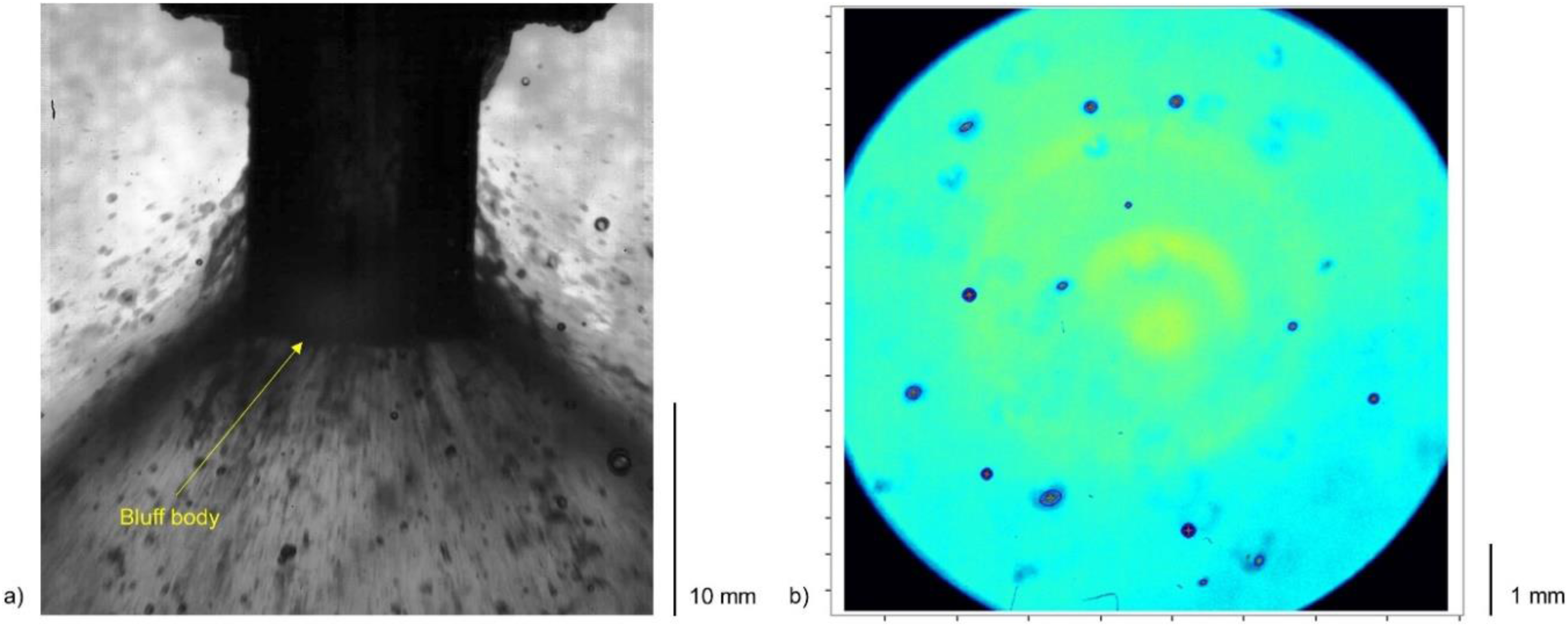
a) Spray image for 10 kg/h air flow rate and 100 kg/h water flow rate for Lc = 10.0 mm. b) Raw image of the droplets for Lc = 10.0 mm case at radial location 150 mm. .
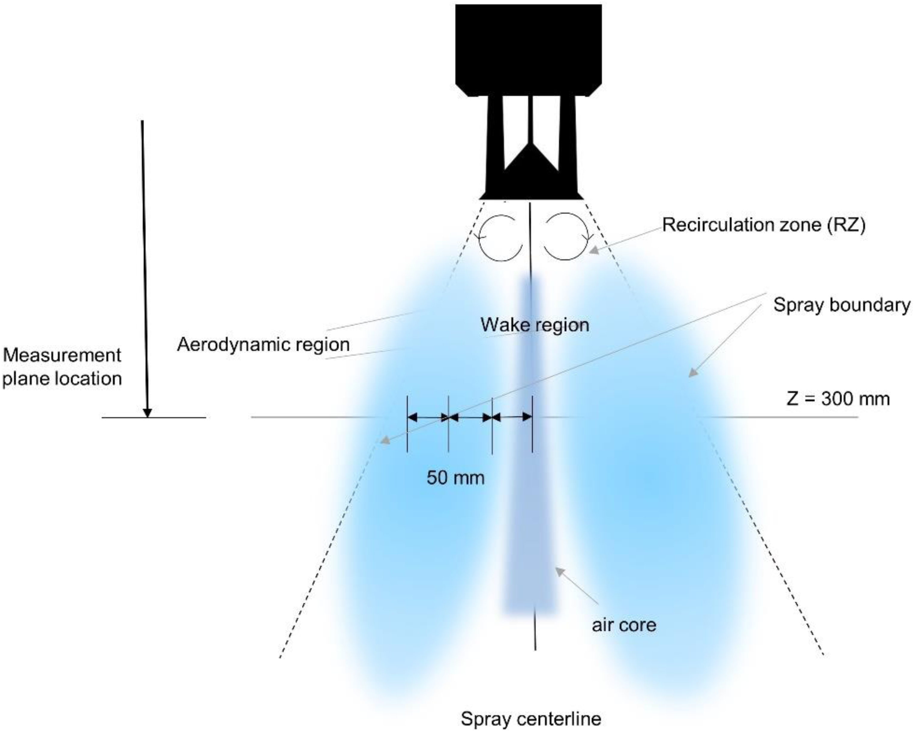
Schematic of the droplet size measurement location for the bluff body-assisted twin-fluid atomizer.
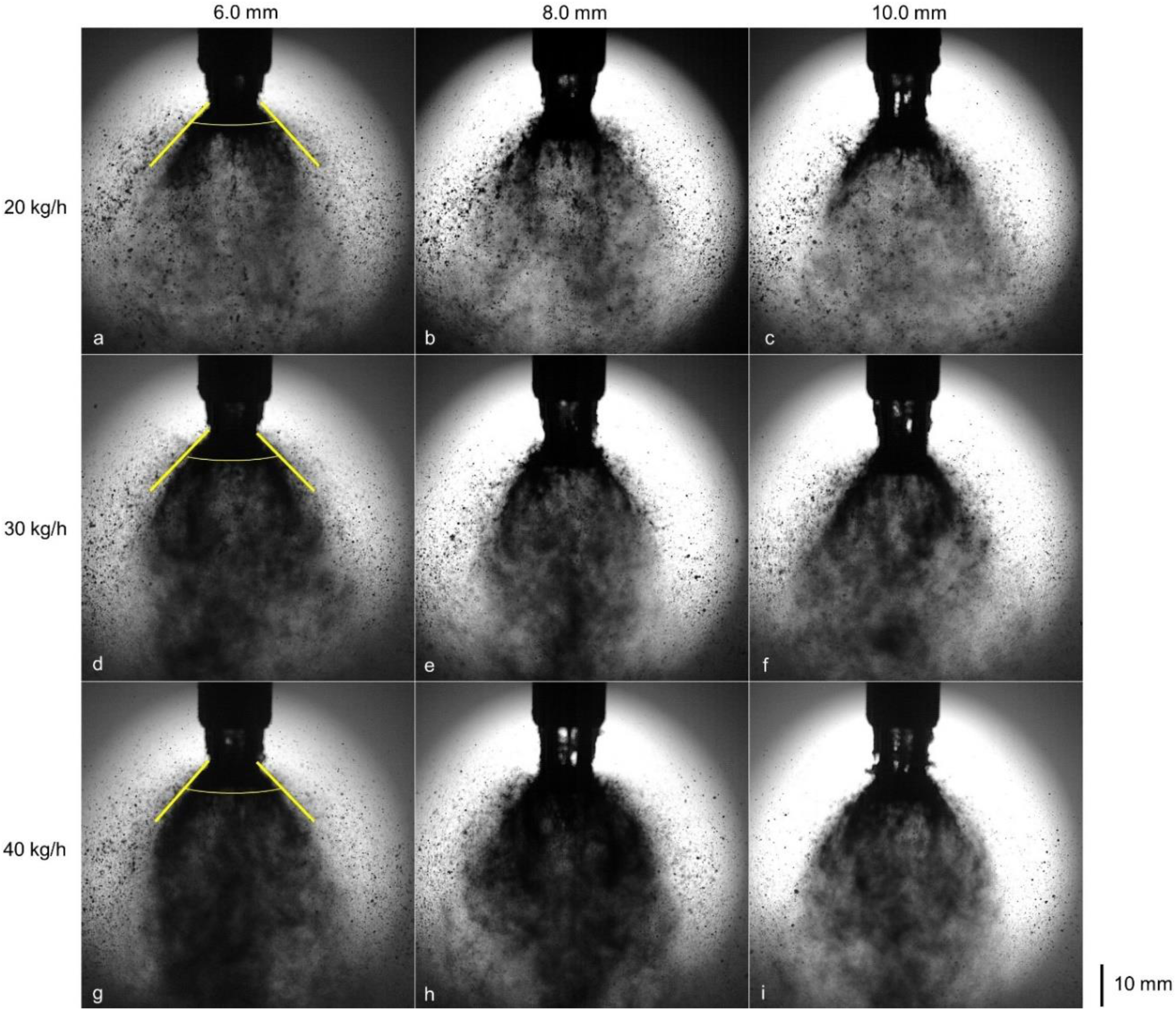
Laser-based backlight imaging pics for the 20 kg/h airflow rate for different water flow rates.
Laser-based backlight imaging pics for the 200 kg/h water flow rate for different airflow rates.
Results
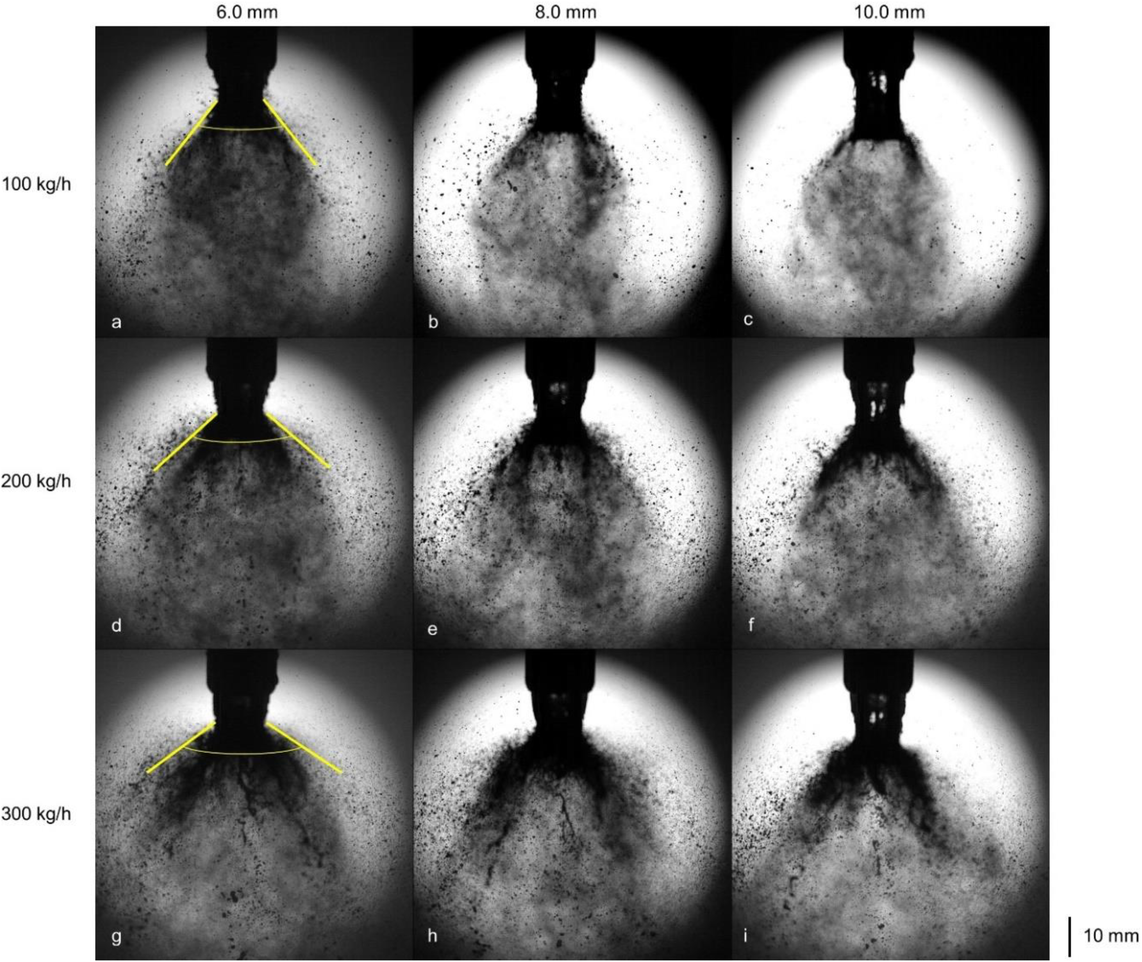
The near atomizer exit spray structure was qualitatively studied for various working conditions using high-speed imaging. The larger field of view (FOV) spray images were obtained for 100 kg/h to 300 kg/h water flow rate for 20 kg/h airflow rate (Figure 7). The relatively larger droplets are formed for the 6.0 mm case due to the early interaction between the sheet and the bluff body (cone). The mist formation is more pronounced in the case of a 6.0 mm atomizer, which might be due to the intense shock interaction with sheet fragments owing to a shorter cone distance (Lc = 6.0 mm). Many droplets are visible due to the darker background as mist-like droplets cloud obstruct the laser light. Note that the laser light intensity is kept minimum (in terms of an ampere) to visualize the spray structure effectively. For the 100 kg/h water flow rate, the spray angle is narrower for all atomizer configurations compared to higher flow rates (300 kg/h) due to the relatively less liquid momentum or velocity, leading to lesser radial momentum after hitting the bluff body (cone) in the former. With the increase in liquid flow rates (say, 300 kg/h), the spray angle increases due to the higher liquid momentum and momentum imparted to the resulting spray after a high-speed impact with the bluff body.
There is some uncertainty regarding the spray angle for different atomizer configurations for liquid flow rates due to the uneven laser light obstruction subjected to the dense spray. There is an apparent ligament structure protruding downstream at the spray centreline (Figure 7 g &h), especially for higher liquid flow rates (say, 300 kg/h) which might be the reason for the larger drop size at the spray centre region at an axial location downstream for lower airflow rates (say, 20 kg/h). For a constant (200 kg/h) water flow rate (Figure 8), an increase in the airflow rate from 20 kg/h to 40 kg/h results in a slight decrease in the spray angle (curved boundary) for all atomizer configurations due to the higher air-jet axial momentum/velocity, leading to less divergence in the two-phase flow after impacting the bluff body (cone). With the increase in airflow rates, the spray becomes more homogenous due to the high-speed air-liquid interaction and the spray-wall impact leading to more mist formation. The drop size becomes smaller with the increased airflow rates (Figure 8g & h).
The droplet size measurements were performed at the Z/D = 100 location downstream from the exit for all three atomizer configurations (6.0 mm, 8.0 mm, and 10.0 mm). Volume-normalized droplet size distribution (DSD) and their cumulative distribution function (curve) are plotted together in Figure 9. The drop size distributions (DSD) are unimodal with slightly skewed towards the smaller droplet sizes. For a given airflow rate (say, 20 kg/h) with a 100 kg/h water flow rate, the distribution peak is around 75–100 µm for all the atomizer configurations. With the increase in liquid loading (say, 300 kg/h) water flow rate, the distribution peak shifted towards a slightly higher value (100–125 µm) which corroborates the ligament structure convecting downstream at the spray centreline (Figure 7). The DSD spread increases from 6.0 mm atomizer to 10.0 mm atomizer configuration for 100 kg/h water flow rate attributed to the less intense impact on the bluff body. In comparison, DSD spread decreases from 6.0 mm atomizer to 10.0 mm for a higher water flow rate (300 kg/h) attributed to the higher impact momentum on the bluff body. Note that the DSD spread is directly linked to the relative span factor (Δ). The cumulative distribution function (green curve) such that (80% of the droplet size by volumes) fall under ∼ 200–250 µm range for all atomizer configurations irrespective of the water flow rates.
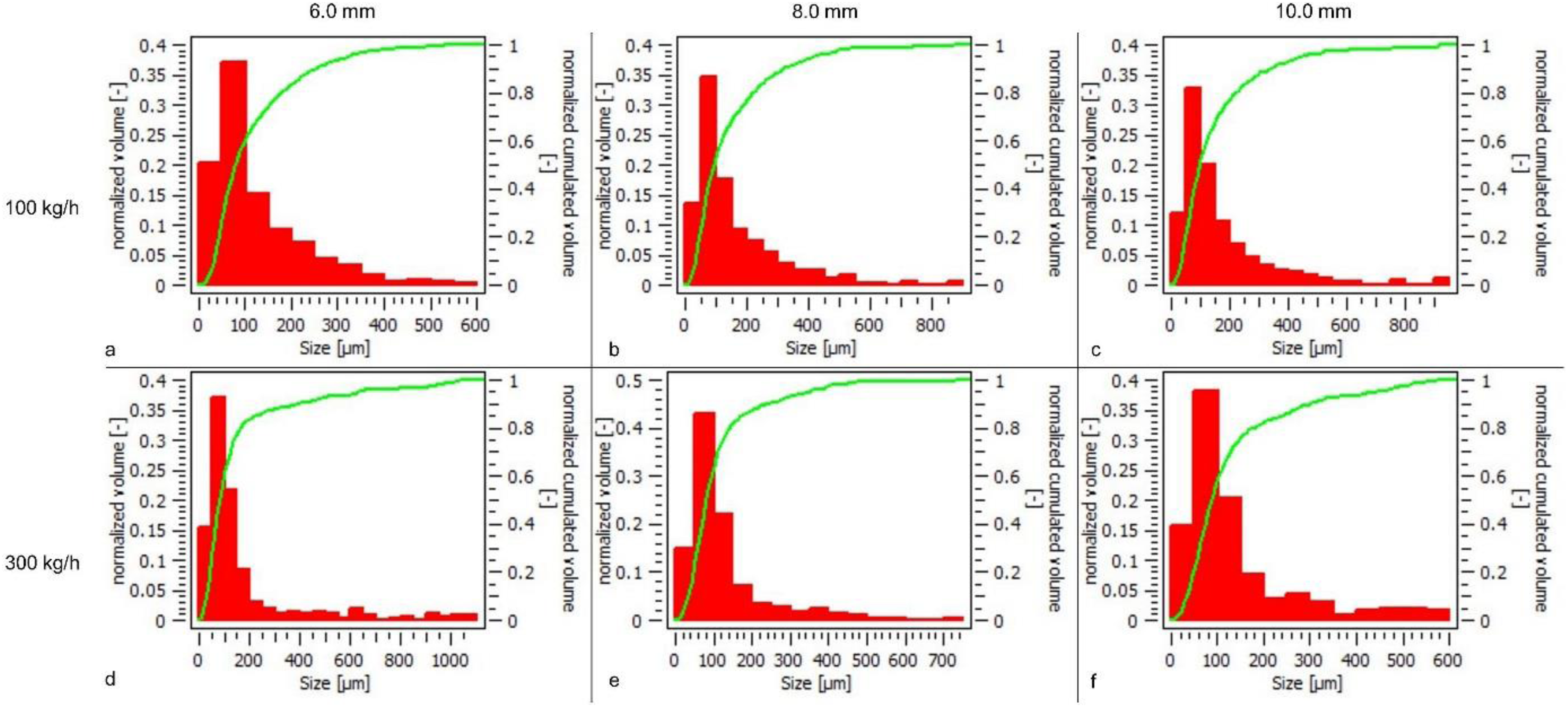
Histogram showing the drop size distribution (normalized volume) and cumulative distribution line (in green colour) for 20 kg/h airflow rate for 100 kg/h & 300 kg/h water flow rate at Z/D = 100 location downstream for 0 mm radial location.
The droplets formed are of irregular shape as elliptical droplets/globules, whose diameter is based on the semi-major and semi-minor axes. The excentricity (shape) of the droplets is based on the ratio of perimeter and diameter. As plotted in Figure 10, for a given airflow rate (20 kg/h) the droplets with higher excentricity (>110%) are formed in relatively larger numbers as we increase cone distance (Lc), and the increment for high excentricity droplets is more with higher liquid loading (say, 300 kg/h). The 10.0 mm cone distance atomizer configuration contains a marginally smaller number of highly excentric (irregular) droplets than the other two configurations (6.0 mm and 8.0 mm). Also, the majority of these irregular-shaped droplets are smaller in size (∼100–600 µm) in the former case (Figure 10 f) owing to the bluff body impact momentum and airfield below the bluff body region.
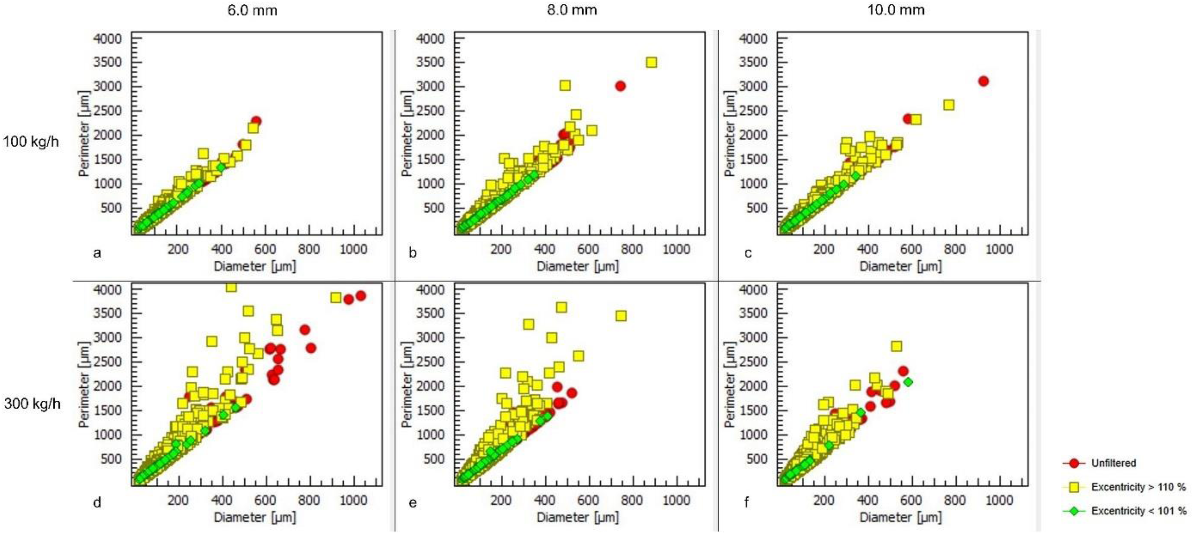
Scatterplot showing excentricity of droplets (in %) for 20 kg/h airflow rate for 100 kg/h & 300 kg/h water flow rate at Z/D = 100 location downstream for 0 mm radial location.
In Figure 11, DSD is plotted for a 200 kg/h water flow rate with a change in airflow rates. For all atomizers, DSD is unimodal with an almost similar distribution peak value (∼100 µm) irrespective of the airflow rate. The DSD spread decreases when the airflow rate increases from 20 kg/h to 40 kg/h, as depicted by the cumulative distribution curve (80% of the droplet size by volume) falling from (∼ 550–600 µm) range for 20 kg/h airflow to (∼175–200 µm) range for 40 kg/h airflow rate which emphasizes the effect of the air-to-liquid ratio (ALR) on the drop size distribution independent of the cone distance (Lc).
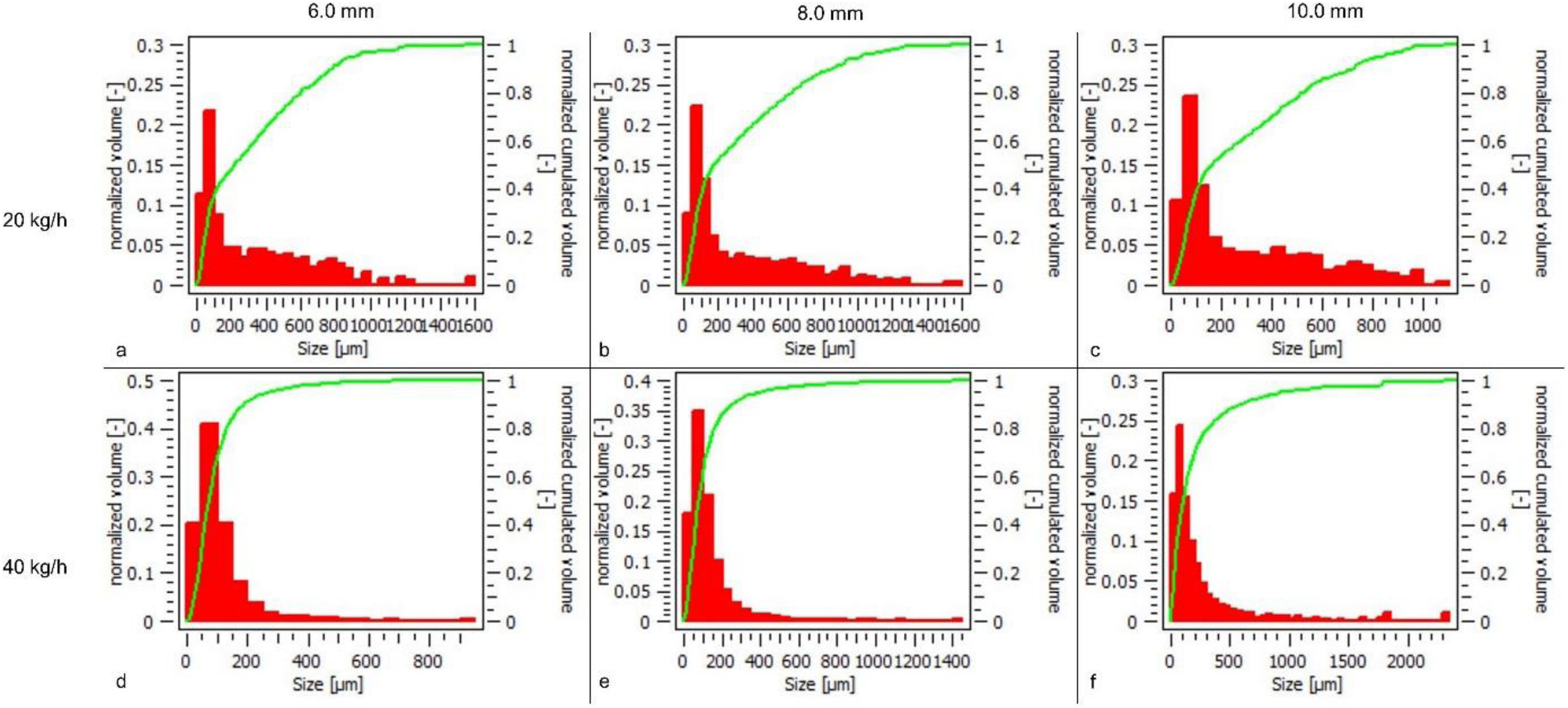
Histogram showing the drop size distribution (normalized volume) and cumulative distribution line (in green colour) for 20 kg/h and 40 kg/h airflow rates for 200 kg/h water flow rate at Z/D = 100 location downstream for 0 mm radial location.
For a 200 kg/h water flow rate with a low (20 kg/h) airflow rate, the 8.0 mm atomizer depicts a larger number of high excentricity droplets than the other atomizer configurations (6.0 mm and 10.0 mm), with relatively constant perimeter for given diameter values for the latter case.
A larger quantity of high excentricity droplets in the former case might be due to the low reflected shock strength at a low airflow rate, resulting in less energy exchange before impacting the thin film formed on the bluff body (Figure 12). For a higher airflow rate (40 kg/h), though the 10.0 mm cone distance atomizer configuration contains a slightly larger number of high excentricity droplets compared to the other two configurations (6.0 mm and 8.0 mm), with a higher perimeter of the droplets than other two configurations (Figure 12 f). The important point is that the high perimeter values for given diameter values in the 10.0 mm atomizer configuration indicate that a large fraction of aspherical droplets is formed due to the spray impacted onto a thin film formed at the bluff body and turbulent airfield below the bluff body region at high airflow rates. Please note that even smaller droplets are formed at a high airflow rate (40 kg/h), droplet perimeters are higher indicating the intense shearing effect resulting in more irregular-shaped droplets.
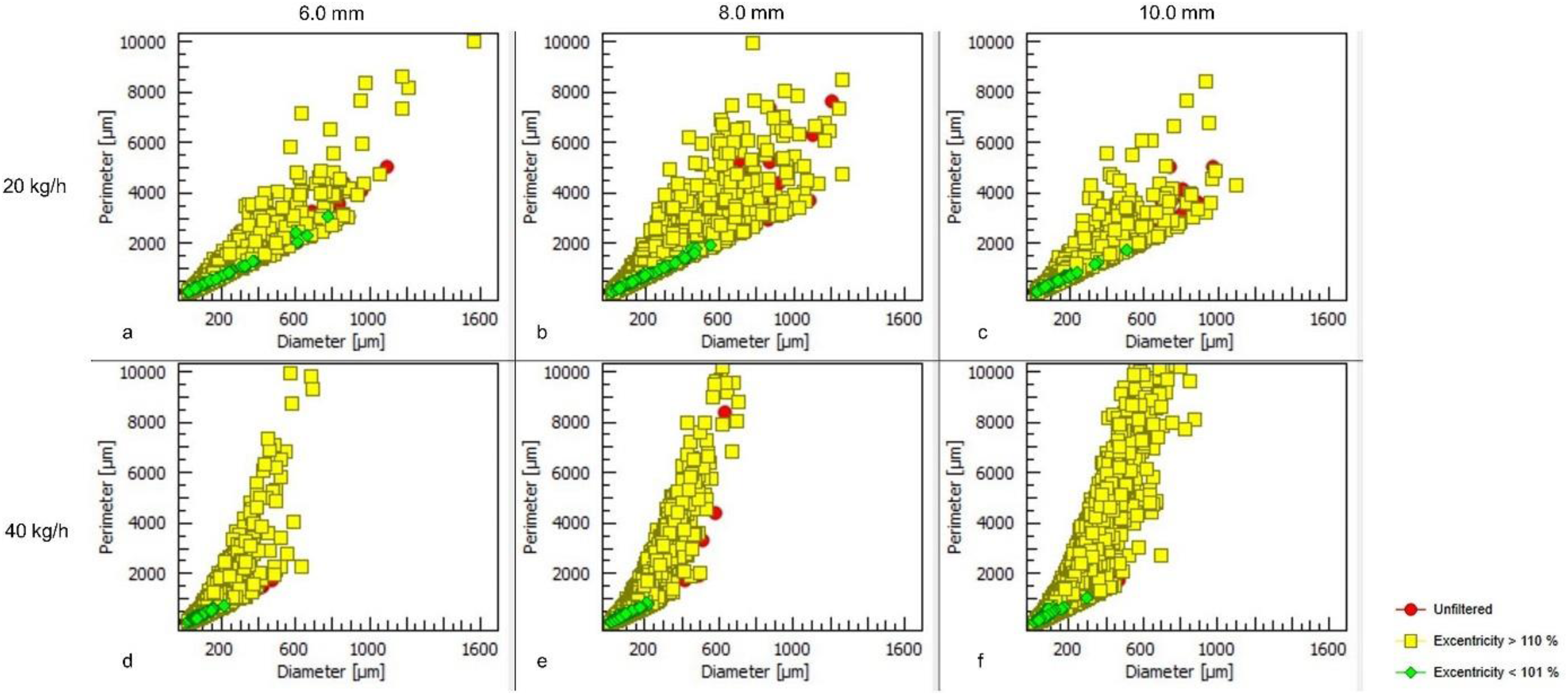
Scatterplot showing excentricity of droplets (in %) for 20 kg/h and 40 kg/h airflow rates for 200 kg/h water flow rate at Z/D = 100 location downstream for 0 mm radial location.
For three radial locations 50 mm apart, the drop size distributions (DSD) and cumulative distribution function (curve) are plotted for fixed airflow and water flow rates, 30 kg/h and 200 kg/h, respectively (Figure 13). The drop size distribution is unimodal and non-symmetric for all atomizer configurations incorporated. The DSD spread is constant at a particular radial location such that 80% of the droplet size by volume falls in the range (∼125–150 µm) for the 50 mm radial location and in the range of (∼225–250 µm) for the 150 mm radial location independent of the atomizer geometry. The above difference indicates the effect of spray-bluff body impact dynamics on the mean drop size and the droplet size distribution (or Relative span factor (Δ)). It is important to note that the 80% droplet size by volume for the 8.0 mm atomizer is slightly narrower than the other two configurations (6.0 mm and 10.0 mm). Apart from the physical geometry (cone distance (Lc) variation), it might be due to the distinct jet dynamics as the liquid sheet interacts with the reflected shock patterns formed by the underexpanded flow (expansion waves at nozzle exit) before impacting the bluff body. Also, spray-bluff body impact momentum led to marginally wider spray formation resulting in comparatively narrow DSD for an 8.0 mm atomizer configuration at a far radial location. The DSD in terms of different distribution functions is plotted in Figure 1B (see Appendix B) for all the radial locations at all the fluid flow rates employed.
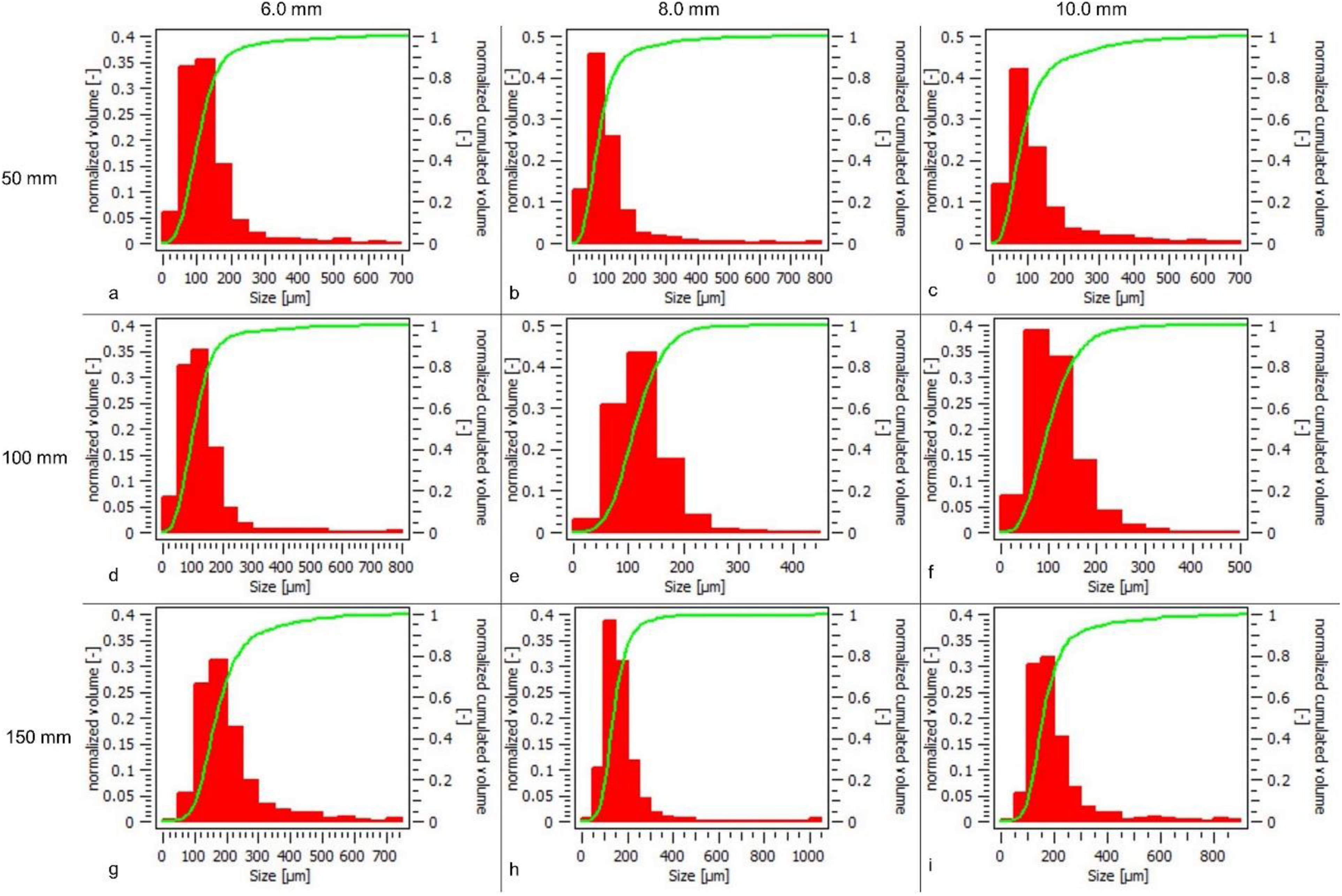
Histogram showing the drop size distribution (normalized volume) and cumulative distribution line (in green colour) for 30 kg/h airflow rate for 200 kg/h water flow rate at Z/D = 100 location downstream for radial locations 50 mm, 100 mm & 150 mm.
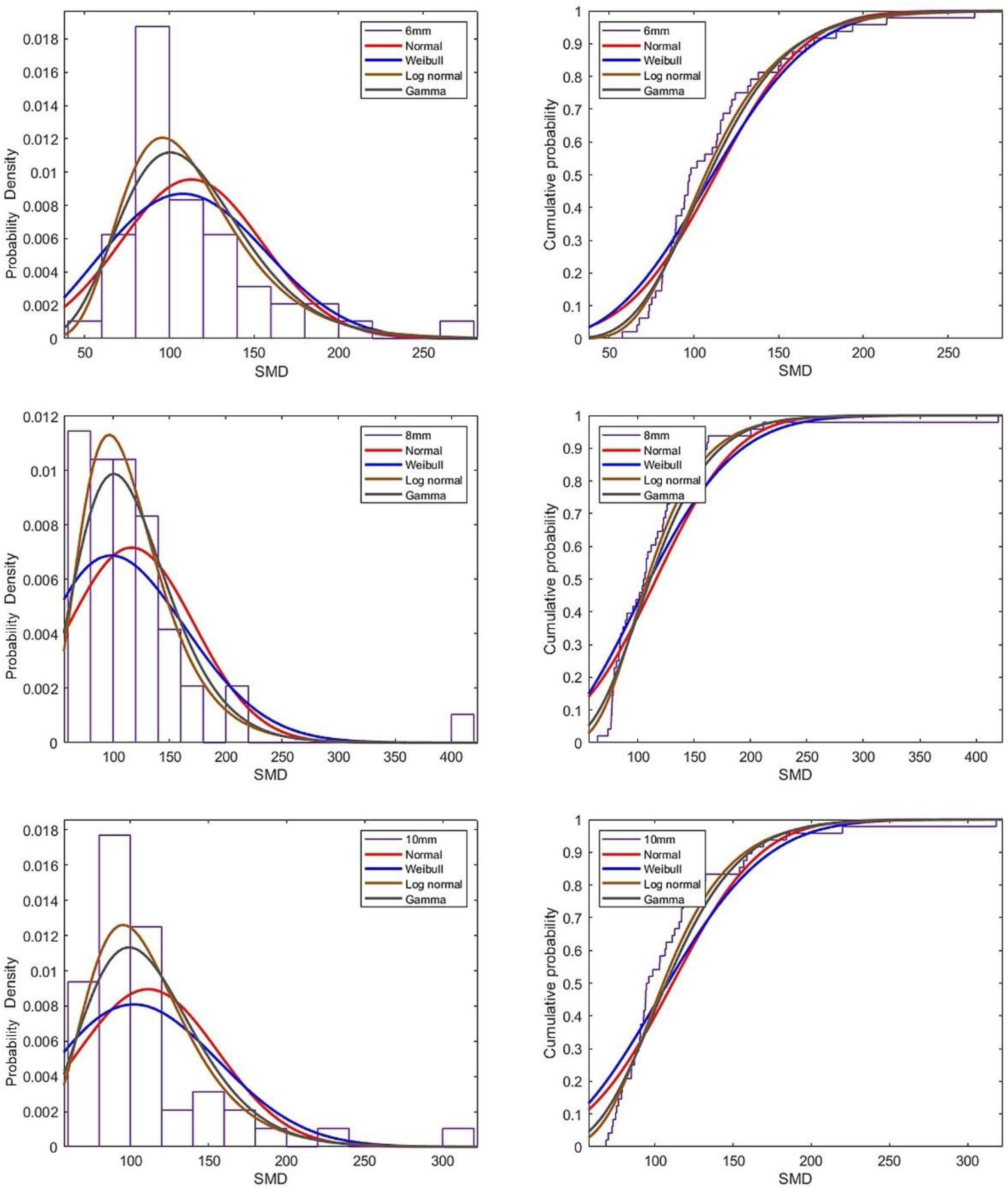
Distribution curve fits including all SMD (in µm) values for all radial locations at various fluid flow rates for all atomizers configurations.
For a given airflow and water flow rates, 30 kg/h and 200 kg/h, respectively, the droplets with higher excentricity (>110%) are formed relatively in larger numbers for all the atomizers at a 50 mm radial location as shown in Figure 14. For 150 mm radial location, a minimum number of relatively larger droplets ranging from ∼200 µm have high excentricity. The decrease in the number of high excentricity droplets as we move radially away from the centreline indicates the spray-bluff body impact dynamics intensity affecting the secondary droplet atomization. The newly droplets formed (due to the crown/splashing) get into a highly turbulent (high shear) airfield at the near-centre region resulting in high excentricity droplets. On the contrary, the less turbulent airfield at far radial locations led to nearly spherical droplet sizes. The important point to note is that perimeter & diameter follow a nearly linear correlation for far-radial location (150 mm) for the majority of the higher excentricity droplets.
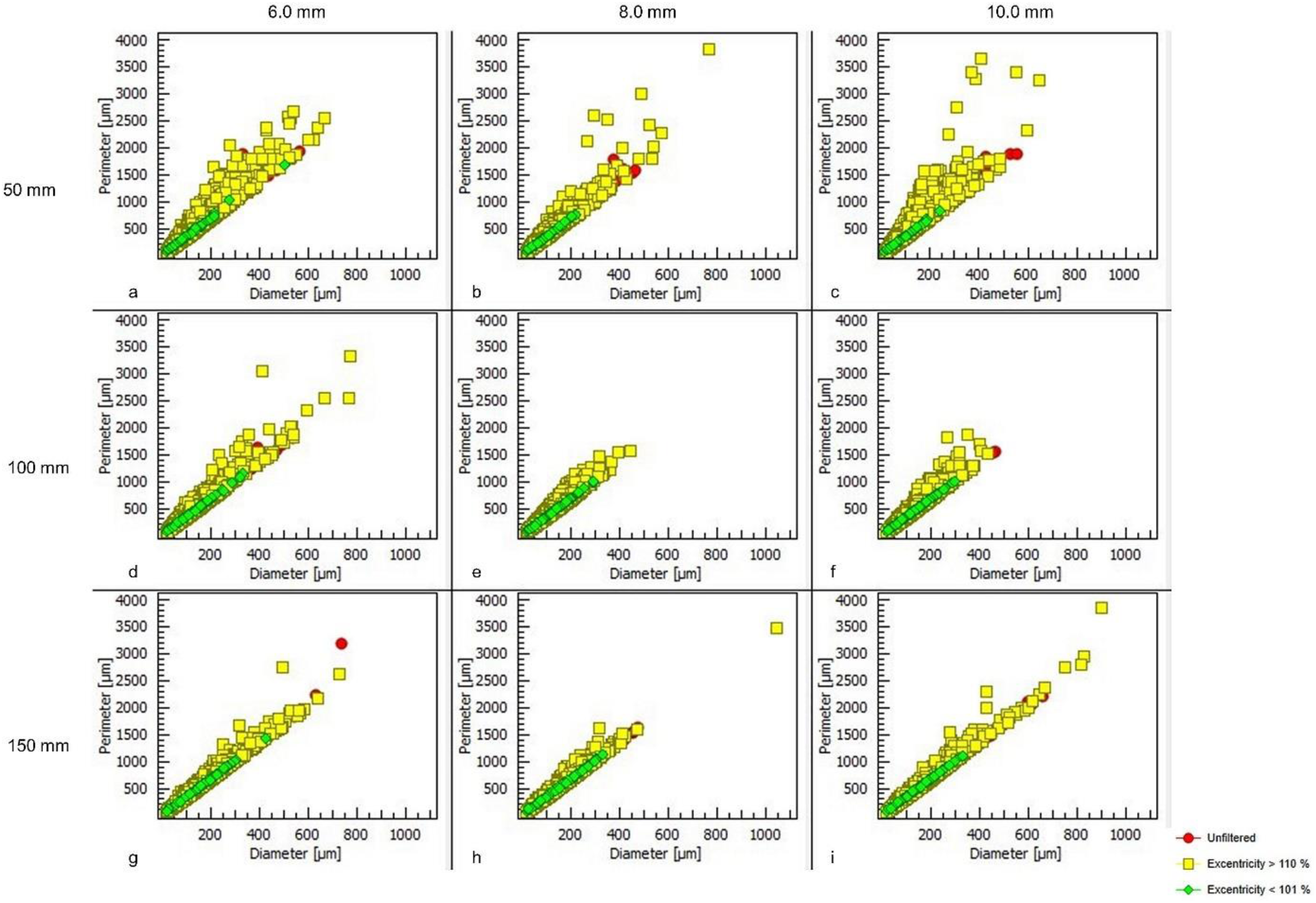
Scatterplot showing excentricity of droplets (in %) for 30 kg/h airflow rate for 200 kg/h water flow rate at Z/D = 100 axial location downstream for radial locations 50 mm, 100 mm & 150 mm.
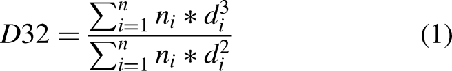
The mean drop size complements the droplet size distribution (DSD) in characterizing the sprays. The calculation of mean diameter by considering the volume and surface area of the droplet is termed Sauter mean diameter (SMD). It is defined as surface-volume mean diameter or D32 such that it gives the estimate in terms of volume to area ratio for the whole spray (Kowalczuk et al.
28
) Please note that the SMD and D32 are used interchangeably for Sauter mean diameter. It is calculated using equation 1:
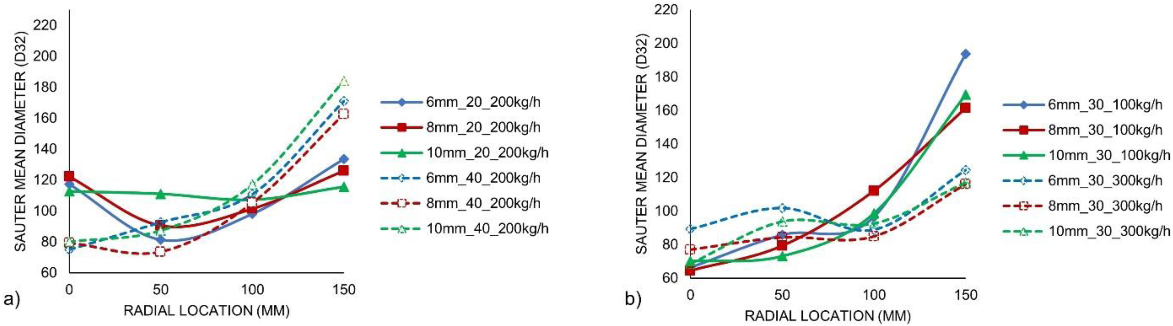
Plot showing a) SMD for 20 kg/h & 40 kg/h airflow rate at 200 kg/h water flow rate b) SMD for 100 kg/h & 300 kg/h water flow rate at 30 kg/h airflow rate, at all radial locations.
Not only does the mean drop size (SMD) value gives a unique value for the overall spray, but the drop distribution can also be translated as a single entity. The Relative span factor (Δ) is a parameter that defines the droplet size distribution with a sole number. As it indicates the uniformity of the spray at a given spatial location, its importance is eminent as Bossard et al.
29
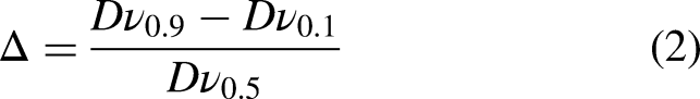
stated that the theoretical formulations employed for drop size distributions, such as Rosin-Rammler etc., lack generality, where the relative span factor (Δ) provide a more suitable representation. It is defined by incorporating percentile-based diameters such as Dv0.1, Dv0.5 and Dv0.9 as the diameters containing 10%, 50% and 90%, respectively, of the droplets (by volume) smaller than this diameter. It gives the estimate in terms of uniformity of the spray distribution. Please note that the RSF and relative span factor are used interchangeably with the symbol Δ. It is given by equation 2:
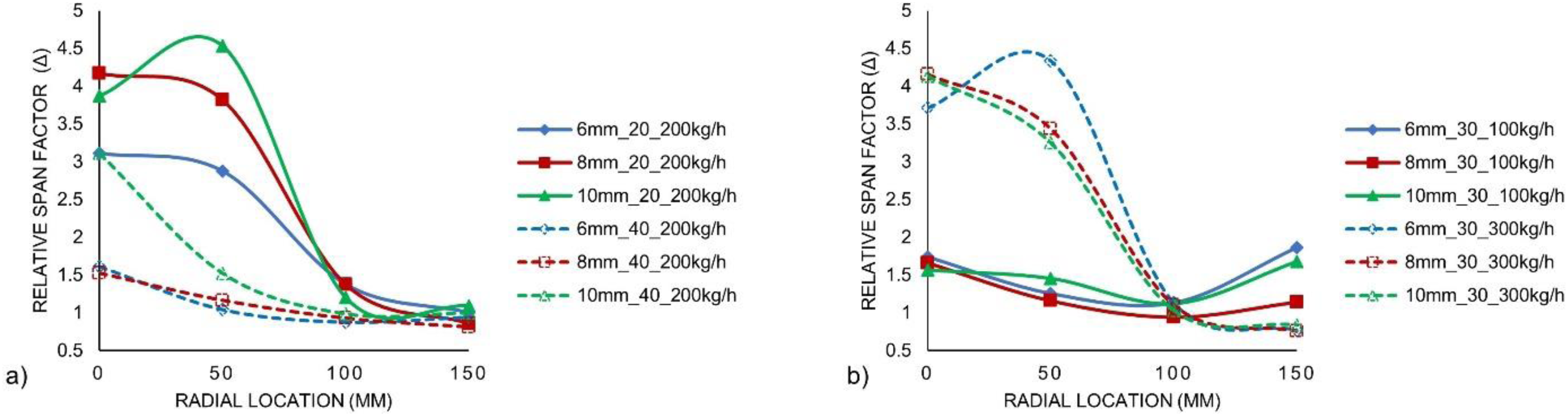
Plot showing a) RSF for 20 kg/h & 40 kg/h airflow rate at 200 kg/h water flow rate b) RSF for 100 kg/h & 300 kg/h water flow rate at 30 kg/h airflow rate, at all radial locations.
Discussion
The findings from the extensive experimental study indicate that there is a certain effect of atomizer physical design (variation of cone distance (Lc) in terms of spray dynamics (sheet interaction with the bluff body), droplet size (SMD) & shape (excentricity) and spatial droplet size distribution (DSD) & cumulative distribution function curve, albeit to a moderate degree.
In our case, the added complexity in the form of the bluff body attachment aids in further liquid disintegration with the spray-bluff body impact on an inclined plane. The high-speed energy exchange with the newly formed ligaments from bluff-body impact leads to the formation of mist-like fine droplets in the spray centreline. Also, when the relative velocities between two phases are high (as in the spray centreline region) the catastrophic breakup regime results in a larger fraction of smaller mist-like droplet formation (Guildenbecher et al. 30 ).
The spray-bluff body impact intensity governs the droplet size distribution (DSD) and cumulative distribution based on the fluid flow rates and cone distance (Lc) variation. DSD and cumulative distribution become uniform with increased liquid loading and airflow rates. Due to the increased turbulence intensities introducing bluff bodies near atomizers that generate strongly separated and reverse flow causes reduced drop sizes and more uniform droplet size distributions (Liu 31 ). They can affect the droplet shape & size, contributing to the lower droplet size but a slightly larger number of high excentricity droplets for higher airflow rates (see Figure 15 a), especially below the bluff body region. On the contrary, at radial locations far from the spray centreline, relatively larger size droplets are formed with a large fraction of nearly spherical droplets, which might be due to the radial momentum not completely transferred to the globules/droplets forming secondary droplets; also, the normal momentum is partially lost due to the high energy impact of the two-phase flow on the bluff body (cone). The recirculation region behind the bluff body can also affect the droplet trajectory and droplet dispersion based on droplet sizes, as mentioned in Chen et al. 32 . After impinging on the bluff body, the larger droplets might follow the outward spray trajectory due to their larger inertia (large radial velocity). At the same time, smaller droplets will travel in the near nozzle vicinity (centreline) of the high-speed spray core.
The excentricity plots depict the intensity of spray-bluff body impact dynamics through secondary droplet characteristics based on different radial locations. High airflow rate (40 kg/h) with 200 kg/h liquid flow rate gives a comparatively large amount of highly excentricity droplets than low airflow rate (20 kg/h) at 0 mm radial location (spray centreline). At the same time, a relatively moderate air flow rate (30 kg/h) gives a higher number of nearly spherical droplets with linear perimeter-diameter correlation at off-centre locations with the same liquid flow rate (see Figure 14).
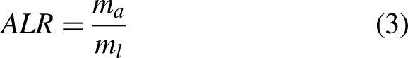
Mean drop size and droplet size distribution (or RSF) depend on fluid flow rates and atomizer (dimension) configurations. The air-to-liquid ratio (ALR) is an important entity to examine the mean droplet size in terms of SMD (D32) and droplet size distribution in terms of RSF (Δ). It is given by equation (3), where ma and ml are mass flow rates of air and water, respectively.
Plot showing SMD trendlines for cone distance (Lc) of 6.0 mm, 8.0 mm, and 10.0 mm for various ALR values for radial locations in terms of X/D at Z/D = 100 location. .
Plot showing RSF (Δ) trendlines for cone distance (Lc) of 6.0 mm, 8.0 mm, and 10.0 mm for various ALR values for radial locations in terms of X/D at Z/D = 100 location. .
Scatter plot showing SMD and RSF (Δ) values for cone distance (Lc) a) 6.0 mm, b) 8.0 mm, and c) 10.0 mm for radial locations 0 mm, 50 mm, 100 mm & 150 mm.
The spray impact on the bluff body (disc or cone) may affect the spatial distribution of the droplets in terms of droplet mean sizes and the droplet number density. The mean drop size and the spray density directly affect both vaporization and combustion aspects; however, combustion characteristics also depend on the type of combustor system (such as industrial boilers), the airflow pattern within combustors, etc. The dense spray region (below the bluff body region) curtails the air-liquid mixing due to the slow air entrainment rate whereas the less dense spray region (off-centre locations in our case) promotes better air-liquid mixing for efficient spray combustion (Law 34 ).
Further study is required to explore the effect of different air jet diameters on the spray behaviour as drop diameter is highly sensitive to the air jet diameters (Padwal et al. 35 ). Spray uniformity will be estimated in terms of spray pattern using a Mechanical Patternator designed in-house specifically for these atomizers by covering only one sector angle (120°) and integrating it for the other two sectors to get whole coverage azimuthally. The patternation has the advantage of estimating the spray volume flux in addition to the spray pattern at different spatial locations providing the spray characteristics in terms of spray homogeneity. Also, mean drop size and drop size distribution (DSD) based on different atomizer configurations (different airflow diameters with fixed cone distance (Lc)) subjected to different air-to-liquid ratios (ALR) need to be investigated to estimate the atomization effectiveness based on atomizer geometry and atomizing air as in real applications compressor power or minimum airflow requirement can be an issue.
Summary
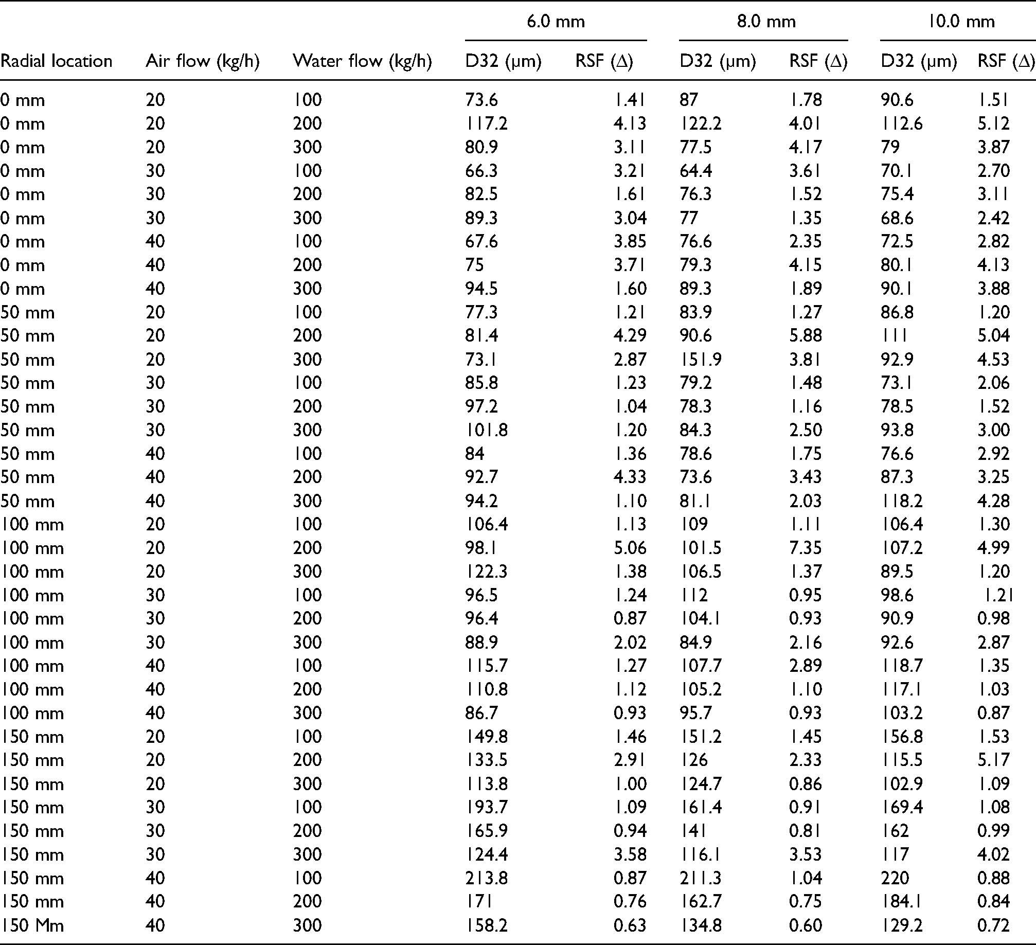
The study reveals the complex spray behaviour associated with droplet formation from different atomizer designs and air-liquid interaction within the atomizer type. The high-speed sheet/ligaments interact with the bluff body-induced shock waves, leading to mist-like fine droplets cloud in addition to a larger ligament structure protruding downstream. Droplet size distribution (DSD) and cumulative distribution become narrower with increased liquid loading and high airflow rates. Excentricity plots hint at the intensity of the secondary spray dynamics as a large fraction of high excentricity droplets are formed at the spray centreline, while nearly- spherical droplets are formed away from the spray centreline. SMD generally increases with an increase in radial locations from the spray centreline attributed to the spray-bluff body impact dynamics leading to different spray characteristics. High SMD values for high airflow rates (40 kg/h) at 150 mm might be due to entrained smaller droplets into the recirculation zone below the bluff body region, as higher droplet number density was observed at the spray centreline. The relative span factor (Δ) follows an inverse trend as it decreases away from the spray centreline. The high RSF value at the spray centreline indicates the large droplet size range formed due to ligament breakup and finer drop sizes formed due to mist formation. Low RSF values at a higher radial location corroborate the aerodynamic atomization such that a smaller number of newly droplets formed are of comparable sizes. SMD and RSF (Δ), when plotted against radial locations in three-dimensional plots for each atomizer configuration, larger SMD values correspond to lower RSF (Δ) values and vice-versa. Sauter mean diameter (SMD) and Relative span factor (Δ) show correlation through cluster formation with some outliers when plotted for all different fluid flow rates employed (Figure 20). The values of SMD and RSF for all atomizer configurations at all radial locations are tabulated in Table 1A (Appendix A).
Plot showing RSF (Δ) Vs SMD (D32) for cone distance (Lc) of 6.0 mm, 8.0 mm, and 10.0 mm for radial locations 50 mm, 100 mm & 150 mm.
SMD (µm) and RSF (Δ) values for all atomizers at various radial locations.
Footnotes
Acknowledgements
The researchers would like to express gratitude for the financial assistance received from Wärtsilä Moss AS for the necessary equipment for the experimental setup.
Declaration of conflicting interests
The author(s) declared no potential conflicts of interest with respect to the research, authorship, and/or publication of this article.
Funding
The author(s) received no financial support for the research, authorship, and/or publication of this article.