
Abstract
In cross-country skiing races, the difference between the fastest and the second fastest time can be minuscule. As in all endurance sports, cross-country skiing requires the use of energy to overcome resistive forces, in this case primarily aerodynamic drag and friction between the skis and snow. Even a slight reduction in either of these can determine the outcome of a race. The geometry of the ski exerts a profound influence on the friction between the skis and snow. As a result of the flexible modern cross-country skis, the camber profile and gliding properties to be influenced by the skiers’ position. Here, based on the location of the normal force corresponding to the plantar pressure, we characterize the ski camber while performing three variations of the downhill tucking position. We found that when gliding on a classic ski, the risk of contact between the kick wax and snow can be reduced by tucking in a leaning backwards position (i.e. by moving the skier’s center of mass backwards). With the tucking position, the percentage of the skier’s body weight that is distributed onto the friction interface at the rear of the skis varies between 63.5% in Gear 7 (leaning forward) on a skating ski and 93.0% in Gear 7 (leaning backwards) on a classic ski.
Keywords
Introduction
As in most elite sporting competitions, the difference in the finishing times for the best and next-best cross-country skiers is often quite small. Because cross-country skiers expend most of their energy to overcome the resistance of aerodynamic drag and friction between the skis and snow, even a slight reduction in these resistive forces can exert a considerable impact on the chances for success, as demonstrated by Street and Gregory. 1 Accordingly, almost every national cross-country skiing team includes technicians who attempt to select and prepare the skis in a manner that reduces friction as much as possible.
The nature of friction between sliding objects and frozen water, has interested researchers for some time now. As early as 1939, Bowden and Hughes 2 concluded that the coefficient of this friction depends on the material at the interface, the extent of loading on the snow, and the temperature. These observations were later extended specifically to cross-country skiing. 3 In a review by Colbeck, 4 many aspects of the contact with snow were discussed, and one of the key topics was the distribution of the load. Previously, in 1949, Eriksson 5 concluded that the geometry of the skis affects ski-snow friction. A thorough review of the resistive forces in ski friction was recently presented by Almqvist et al., 6 they discussed the importance of aspects to be considered for the advancements in understanding ski friction.
In general, research on snow-ski friction utilizes three different approaches. First, there are the theoretical studies, which provide us with the physics and mathematical backbone of friction modeling. Both Glenne 7 and Lehtovaara 8 presented mathematical expressions for frictional behaviors that are recognized in skiing, and both works describe a decreasing friction coefficient as the load increases. The contact between the ski base and snow has been examined in greater detail, at the microscopic level, by both Theile et al. 9 and Mössner et al. 10 Studying the compaction of pre-compressed snow Theile et al. 9 concluded that during the first 10 µm the snow crystals in the top layer experienced a brittle fracture deformation process. After fracture deformation, snow compaction enters an elastic regime in which an increasing load elastically deformed the snow another 20 µm. Thereafter, an increasing load was found to plastically deform the snow. The contact mechanical simulations by Mössner et al. 10 showed that the contact pressure between a ski base and a single grain might be as high as 100 MPa, and the results are in line with the local deformations suggested by Theile et al. 9
The second major approach employed in this area of research, is referred to as component testing designed to limit the influence of unwanted parameters to enable studying a single aspect of ski friction. Both Giesbrecht et al. 11 and Rohm et al. 12 used miniature skis with a single flat contact zone, in order to remove the ski-camber profile and thereby control the apparent load in a simpler way. Because skis are very complex, their methodology should reduce the uncertainties, that is, studies on solely ski-base structures, material and preparation, can be done with higher accuracy.
The third approach is full-scale testing of real cross-country skis, with the advantage being that it is closer to the race situation. In this case, it is the full combination of all the different parameters that renders the friction, but it is a difficult task to discern exactly how and to what extent it occurs. For instance, there is a certain combination of ski-camber profiles and ski-base structures that will produce the most beneficial interaction effects and thus the lowest friction. Schindelwig et al., 13 ran tests in a purpose-built unidirectional rig, loading and guiding a single real cross-country ski, indoors in a controlled environment. The objective was to investigate the temperature underneath the ski, and the tests showed that the temperature is different along the length of the ski. They also used a device to analyze the pressure distribution along the ski, and these measurements provided insight into how the temperature and friction are likely to vary. Hasler et al., 14 investigated the precision of the ski-tribometer, that Schindelwig et al. previously used. Their paper shows that ski friction testing is a delicate matter, even in a controlled environment. They showed that when performing 50 tests in a row, the coefficient of friction may either converge to a stable value or continuously diverge, depending on the test parameters. Lemmettylä et al., 15 investigated the performance of a ski-tribometer similar to the one used in other studies.13,14 They also experienced the issues with either converging or diverging coefficient of friction over a series of 50 tests. Budde and Himes, 16 utilized a sledge with a pair of skis running tests outdoors. They did a thorough work, studying the influence of the wax under different conditions. They also tested the influence of the ski-base structure, which was characterized as cold and warm, without presenting any details of the characteristics of the structures’ topographies. The present study falls into this category and aims to provide a further understanding of the interaction between the skier, ski boot, and the camber profile. The results will provide for better experiment design of ski friction tests where the ski-camber profile is considered, as well as facilitate the interpretation of the results.
During cross-country skiing, the ski exhibits dynamic loading conditions. In the skate skiing discipline alone, there are seven different gears, 17 which are used at different speeds and involve different dynamic loading patterns on the skis. On top of that, each individual athlete has his/her own style which will load the ski differently, 18 therefore, a good ski should perform well in all gears. On the straight downhill segments where the athlete tries to maintain a stationary Gear 7 (downhill tucking) (G7) posture, differences in the restive forces become apparent. Ski technicians have known for a long time that there is a correlation between performance at different conditions and the ski-camber profile. When ski technicians are trying out the skis for the race, they test which skis have the optimal ski-camber profiles, and this is done by sliding downhill in the G7 position to evaluate the glide performance. When Breitschädel19,20 analyzed the ski-camber profile characteristics of the ski fleet used by the Norwegian National Team, he concluded that the skis considered suitable by the team’s technicians for cold and warm conditions have different cambers. The ski-camber profile will determine the locations of the contact zones, that is, the interfaces where the ski-snow friction takes place. Bäckström et al., 21 investigated ski-camber profiles and developed a method to measure the pressure distributions under the ski, a parameter which is not frequently presented and has not yet been very thoroughly investigated.
Although reports on full-scale testing of cross-country skis are readily available, both the loading conditions and corresponding ski-camber profiles are not always well documented. This is, however, of utmost importance when conducting studies where the loading conditions are varied. For example, a load increase could result in either an increased contact pressure or an increased contact area, or both, and to discern the prevalent condition one would have to know the ski-camber profile. However, when testing the same skis under the same loading conditions, it is not a prerequisite to know the ski-camber profile, although knowing it could provide additional insights. This paper presents an investigation of how the athlete interacts with their skis while performing the G7 position and how this affects the ski-camber profile and the ski-snow friction interface. The main questions for the current study are: (i) How does the athlete’s position influence the ski-camber profile and ski-snow friction interface? and (ii) How does the load transfer interface affect the ski-camber profile and the ski-snow friction interface?
Theory
In this paper the ski-camber profiles of both a classic- and a skate-ski, will be considered as a function of two important factors namely, the execution of the G7 position and the skier-to-ski load transferring interface. In reality, the ski-camber profile varies due to the athlete’s execution of the G7 position resulting in variations of the athlete’s center of mass , illustrated in Figure 1 as the origin of the gravitational force (red arrow). By measuring the plantar pressure, which is illustrated in the red circle in Figure 1, the Normal Force Location (NFL) where the ski boot transfers the load to the ski binding can be calculated. The shape of the ski boot’s sole constitutes the interface at which the load is transferred to the binding. The ski camber height, depicted in the blue circle in Figure 1, is defined as the distance between the ski base and the underlying surface. Herein, the coordinate system will be defined as
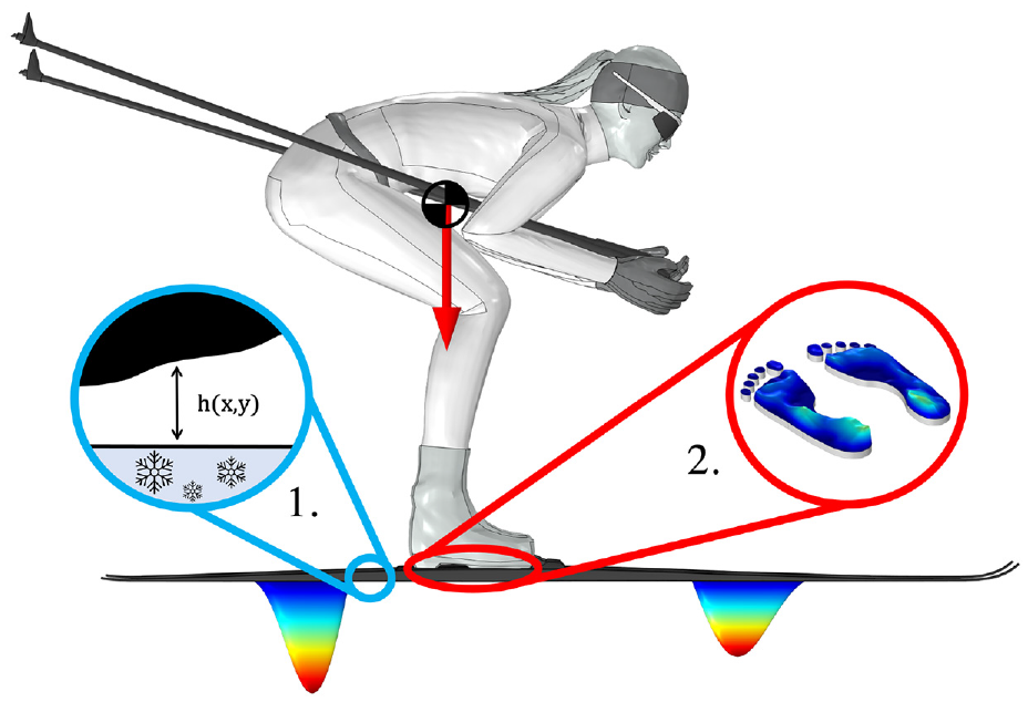
Schematic illustration of the parameters of primary interest in the present study. The skier’s center of mass and corresponding gravitational force are located somewhere over the feet. The reaction pressure is exerted underneath the skis. In circle 1 (blue), the camber profile is defined as the distance between the base of the ski and the underlying surface, as a function of the length and width of the ski. Circle 2 (red) illustrates plantar pressure.
Figure 1 also shows the contact pressure distributions over the front- and rear friction interfaces. In reality, the load is not partitioned equally over the front- and rear friction interfaces and the contact pressure is not uniformly distributed over them. 21 In this work, the load partitioning will, however, be calculated based on that the pressure distributions are uniform. The contact zones, with the uniform pressure distributions, will be determined based on the definition presented by Breitschädel. 20 More precisely, Breitschädel considered that there is contact with the snow where the ski camber height is smaller than 50 µm when measured against the counter surface in a device that measures ski-camber profiles. In this work, the counter surface is the stone in the SkiSelector, 22 which was used to measure ski-camber profiles at different loads.
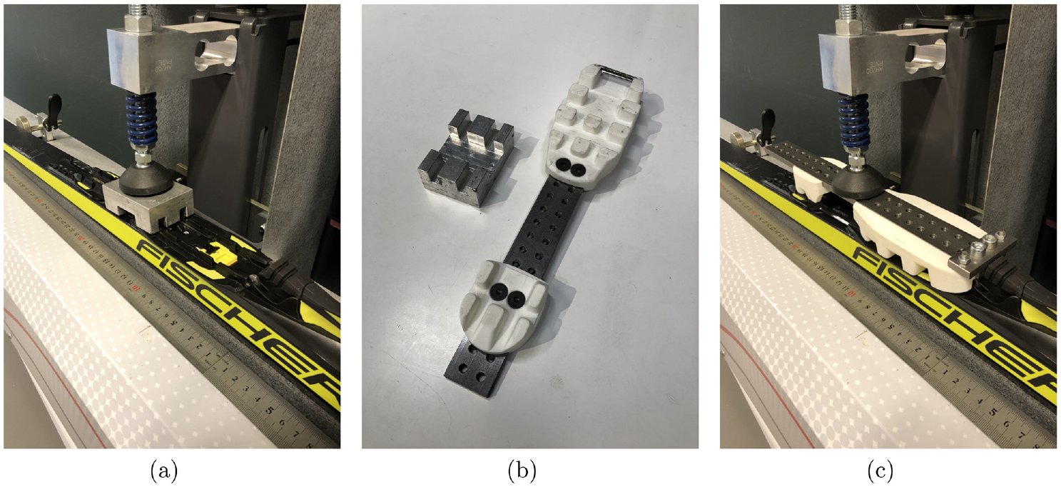
If we adopt Breitschädel’s 50 µm contact criterion and assume that the pressure is distributed symmetrically around the center of the contact zone, then we can calculate the partitioning of the load between the front- and rear friction interfaces as follows. Let us first consider force equilibrium in the vertical direction, that is

where

where
now
Method
Our approach involves the following four intermediate steps: (i) measuring the athlete’s plantar pressure, (ii) analysis of the plantar pressure distributions, (iii) ski-camber profile measurements at the NFL, and thereafter, (iv) analysis of the ski-camber profiles.
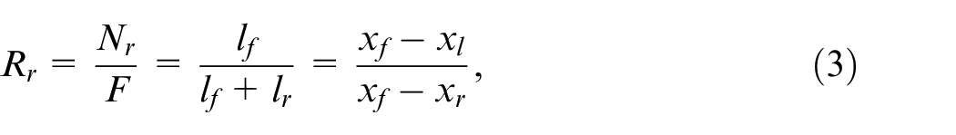
For measurement of plantar pressure, a male athlete with 28.5 cm foot size and body weight of 70 kg was equipped with Medilogic WLAN insoles, 23 with which the athlete’s plantar pressure could be measured. The athlete was asked to perform three different variations of the G7 position, shown in Figure 2. In the first G7 position, depicted in Figure 2(a), the athlete was leaning forward. This position, referred to as Gear 7 (leaning forward) (G7 f ,) can be used by athletes for resting in a downhill segment. The second G7 position, Gear 7 (neutral position) (G7 n ) where the athlete is in a neutral position, is depicted in Figure 2(b). In this position, the athlete feels most well-balanced, and it is perhaps the most typical G7 position. The third G7 position, Gear 7 (leaning backwards) (G7 b ) where the athlete is leaning backwards, is depicted in Figure 2(c). This position has a reduced resting efficiency, because the moment caused by the shifted body weight requires the leg muscles to be active during G7 b .
Athlete in three different Gear 7 (downhill tucking) (G7) positions: (a) (G7 f ) athlete is resting and leaning forward, (b) (G7 n ) athlete is in a neutral tucking stance, and (c) (G7 b ) athlete is focused and leaning backwards.
The second step is to analyze the plantar pressure measurements to determine the NFL, which determines where the loads should be placed on the ski relative to the BP (indicated on the ski by the manufacturer). Herein, it was estimated that the tip of the insole and the binding bar on the boot were located at the same position. The movable bindings were set to a neutral position (0/0), and this locates the binding bar at the BP.
The third step is to measure ski-camber profiles, using the normal force locations obtained from the analysis of the plantar pressure distributions. This will be done by measuring the ski-camber profile when loaded with the force equivalent of 35 and 70 kg, that is, the athlete’s half- and full-body weight, at the NFLs, corresponding to the three G7 positions. The skis used in this investigation are Fischer Speedmax 3D Skate Plus (186 cm) and Fischer Speedmax 3D Classic Plus 902 (197 cm).
24
Note that, the objective is to show how cross-country skis behave in general when they are subjected to different load conditions and load transfer interfaces, not to compare the response of different models of skis nor of different brands. There are several devices that can be used to measure ski-camber profiles at different loads. The one used in the present analysis is of the brand SkiSelector,
22
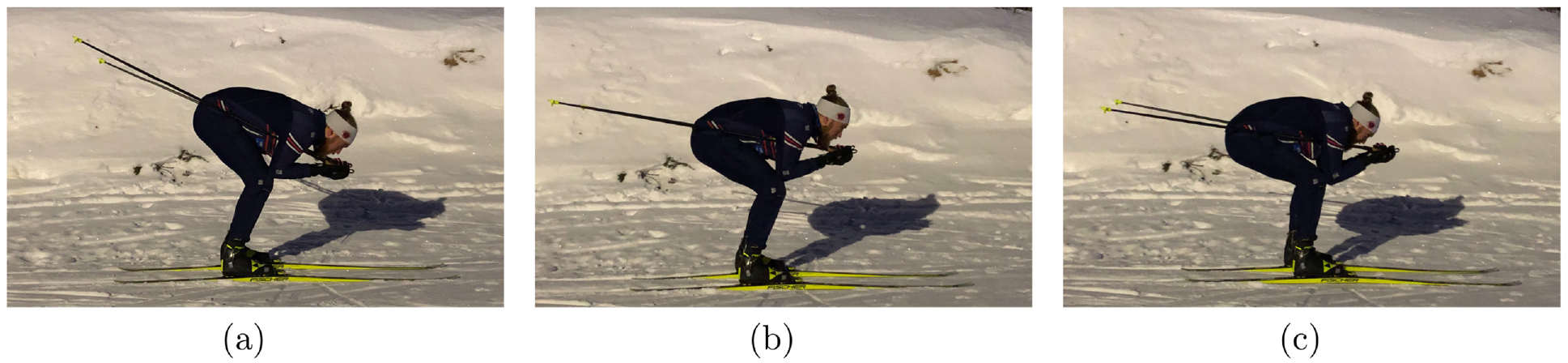
which has an accuracy of 10 µm according to the manufacturer. A physical stopper which can be seen in the upper left corner of Figure 3(a), can be adjusted to assure that the ski is loaded at the same
Measurement setup at the SkiSelector, using the Conventional Block (CB) (a) and using the Measurement Boot (MB) (c). The sole of the CB and the MB is shown in (b).
The fourth step is the analysis of the ski-camber profile measurements. Here the load partitioning between the rear- and front friction interfaces, will be calculated based on the contact criterion defined by Breitschädel, 20 in combination with equation (3) and the corresponding apparent contact area will be presented, and the load partitioning calculated.
Table 1, presents the
Ski-camber height measurements at the end of the rear- and front-contact zones (RCZ and FCZ) of a classic ski loaded 160 mm behind the BP.
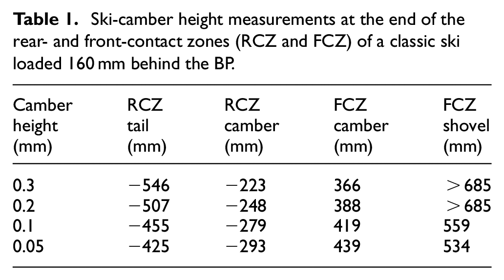
Here is an example of how to calculate the load partitioning using equation (3) and the ski-camber measurements presented in Table 1. By calculating the middle point of the rear- and front-contact interfaces
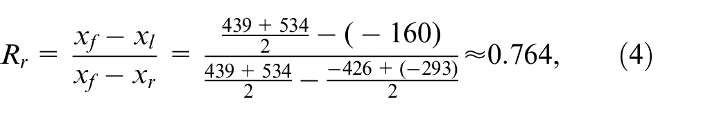
where
Results and discussion
From the plantar pressure measurements with the athlete’s different G7 positions, the plantar pressure distribution could be extracted. Figure 4 depicts three plantar pressure distributions, corresponding to the athlete’s three G7 positions, shown in Figure 2. It can be seen from Figure 4, that the plantar pressure from the G7 f -, G7 n -, and G7 b positions results in clearly distinguishable distributions. The NFL (for each foot), illustrated with a red arrow, highlights where the center of mass is located in each position. The absolute value of the movement is not particularly important, as all athletes are different, but it is noteworthy that there is a distinguishable difference.
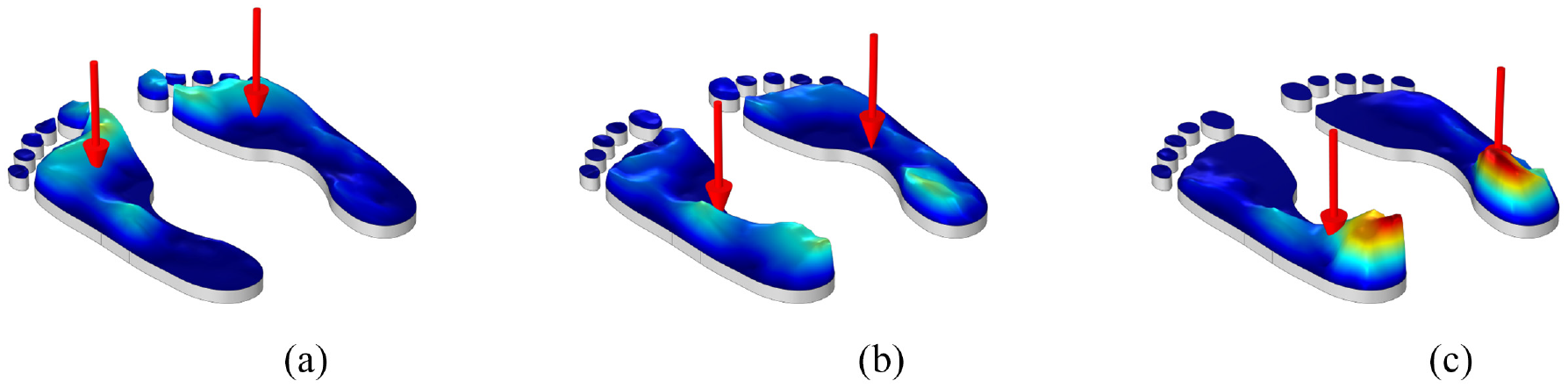
Plantar pressure distributions on the athlete’s 28.5 cm long foot, for the three different Gear 7 (downhill tucking) (G7) positions, shown in Figure 2. The red arrows show the Normal Force Location (NFL) on both the left- and right foot (LF and RF): (a) Gear 7 (leaning forward) (G7f ). The NFL is on the LF 9.9 cm and RF 10.5 cm behind the tip of the insole, (b) Gear 7(neutral position) (G7n).The NFL is on the LF 16.6 cm and RF 15.8 cm behind the tip of the insole, and (c) Gear 7 (leaning backwards) (G7b). The NFL is on the LF 22.2 cm and RF 22.3 cm behind the tip of the insole.
To simplify the analyses, we will continue by assuming that the NFL, measured from the tip of the insole, for G7 f , G7 n , and G7 b , are 100, 160, and 220 mm, respectively, and the ski boot extends from 0 to 300 mm behind the binding. These three NFLs correspond to approximately 35%, 55%, and 75% of the length of the foot.
Ski-camber profile measurement at half-weight load
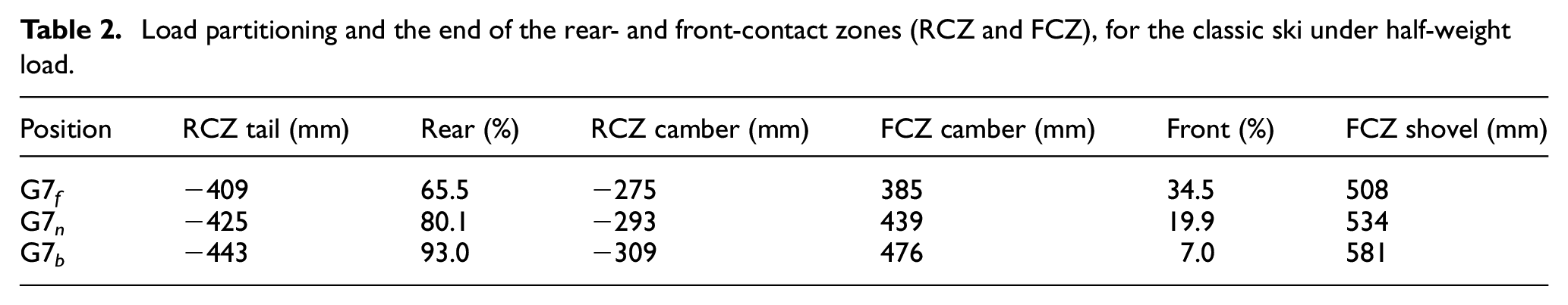
Ski-camber profiles under a load of 35 kg, corresponding to equal weight distribution between the feet, are depicted in Figures 5 and 6. The dashed lines correspond to measurements using the CB method, and the solid lines correspond to measurements using the MB. The three different colors of the ski-camber profile curves correspond to the three different G7 variations. The full length of the ski is not included in the figure, it extends from −900 to 900 mm outside the figure, this applies to Figures 5–8. The blue curves correspond to measurements with the NFL 100 mm behind the BP that is, G7 f , the red curves correspond to the NFL 160 mm behind the BP that is, G7 n , and the green curves correspond to the NFL 220 mm behind the BP that is, G7 b . Depicted in Figure 5, are the ski-camber profiles from a classic ski. The general pattern shows that using the measurement boot makes the ski collapse slightly more than using the conventional small block. Figures 5 and 6 show that the G7 variations influences the ski-camber profile in the order of tenths of millimeters. Notice that 0.3 mm is a small distance from the kick wax to the snow, indicating there is a risk that the kick wax will get into contact with the snow in the G7 f position. Positioning the athlete in a G7 b or G7 n reduces this risk. According to equation (3), the load supported by the rear- and front-friction interfaces can be calculated and the result can be seen in Table 2, where the load supported by the rear frictional interface varies between 65.5% and 93%. Notice that, the front- and rear ends of the 0.3 mm kick wax pocket measured in the G7 n , are located at −203 and 363 mm, respectively, when using the measurement boot, and at −223 and 366 mm, respectively, when using the conventional small block.
Load partitioning and the end of the rear- and front-contact zones (RCZ and FCZ), for the classic ski under half-weight load.
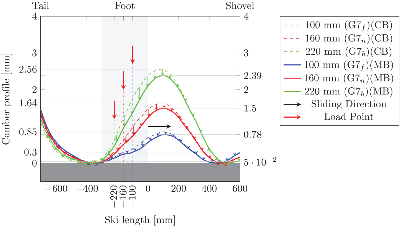
Classic ski camber profiles, for the three Gear 7 (downhill tucking) (G7) positions depicted in Figure 2, corresponding to the plantar pressure distributions and Normal Force Location (NFL) shown in Figure 4. The ski is under half-weight load (35 kg), distributed by the Conventional Block (CB) (dashed lines) and the Measurement Boot (MB) (solid lines). The maximum camber heights are indicated with thin gray lines and corresponding axis values, CB to the left and MB to the right. Breitschädel’s 50 µm contact criterion defined in Breitschädel 20 is indicated with the thin gray line, slightly above the counter surface.
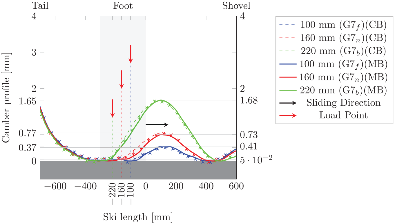
Skate ski camber profiles, for the three Gear 7 (downhill tucking) (G7) positions depicted in Figure 2, corresponding to the plantar pressure distributions and Normal Force Location (NFL) shown in Figure 4. The ski is under half-weight load (35 kg), distributed by the Conventional Block (CB) (dashed lines) and the Measurement Boot (MB) (solid lines). The maximum camber heights are indicated with thin gray lines and corresponding axis values, CB to the left and MB to the right. Breitschädel’s 50 μm contact criterion defined in Breitschädel 20 is indicated with the thin gray line, slightly above the counter surface.
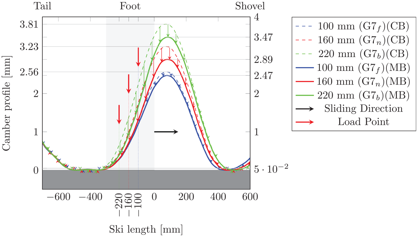
Classic ski camber profiles, for the three Gear 7 (downhill tucking) (G7) positions depicted in Figure 2, corresponding to the plantar pressure distributions and Normal Force Location (NFL) shown in Figure 4. The ski is under full-weight load (70 kg), distributed by the Conventional Block (CB) (dashed lines) and the Measurement Boot (MB) (solid lines). The maximum camber heights are indicated with thin gray lines and corresponding axis values, CB to the left and MB to the right. Breitschädel’s 50 μm contact criterion defined in Breitschädel 20 is indicated with the thin gray line, slightly above the counter surface.
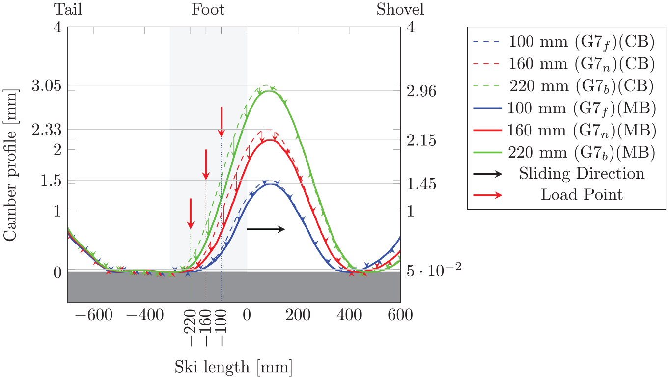
Skate ski camber profiles, for the three Gear 7 (downhill tucking) (G7) positions depicted in Figure 2, corresponding to the plantar pressure distributions and Normal Force Location (NFL) shown in Figure 4. The ski is under full-weight load (70 kg), distributed by the Conventional Block (CB) (dashed lines) and the Measurement Boot (MB) (solid lines). The maximum camber heights are indicated with thin gray line and corresponding axis values, CB to the left and MB to the right. Breitschädel’s 50 μm contact criterion defined in Breitschädel 20 is indicated with the thin gray line, slightly above the counter surface.
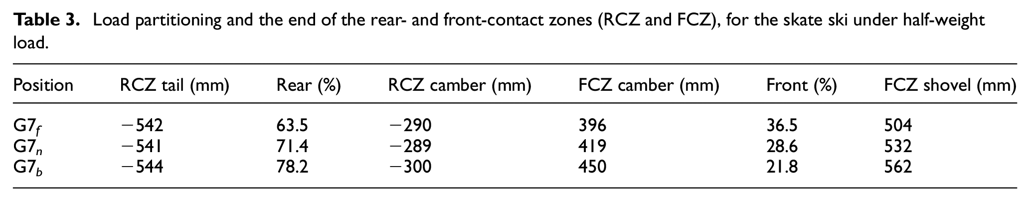
Depicted in Figure 6 are the ski-camber profiles from a skating ski under half-weight load (35 kg). The figure shows that the camber height increases with 1.00 mm when the athlete moves from G7 f to G7 b , it can also be seen that the front contact zone moves forward when the athlete moves from G7 f to G7 b , actually by 58 mm. Related to this, is that the weight carried by the rear friction interface will increase when the athlete moves from G7 f to G7 b , in this case from 63.5% to 78.2%. The load partitioning data for each of the three G7-positions can be seen in Table 3. Figure 6 also shows that the MB decreases the maximum height of the ski-camber profile, however, the difference is not as pronounced in the G7 f position where it is only 0.09 mm. The reason that the ski-camber profile decreases when the CB is replaced by the MB, is that it distributes the load over a larger area, reaching all the way up to the balance point where the stiffness is less and therefore deforms the ski more.
Load partitioning and the end of the rear- and front-contact zones (RCZ and FCZ), for the skate ski under half-weight load.
Ski-camber profile measurement at full-weight load
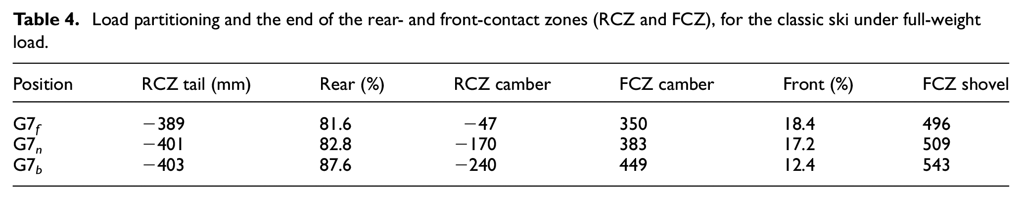
Depicted in Figure 7 are ski-camber profiles from the classic ski at full-weight load (70 kg), and the load positions are identical to the ones in Figure 5. The dashed lines correspond to measurements using the CB method, and the solid line corresponds to measurements using the MB. The figure shows distinguishable different ski-camber profiles (at least a 0.3 mm collapse) when the different G7 positions are used. For instance, when the athlete is applying their full weight on one ski in the G7 b position, the ski collapses less than at half weight in the G7 n position, and there is no risk for contact according to Breitschädel’s contact criterion. When the ski is loaded with the athletes full weight on the measurement boot and the athlete is in the G7 n position, there is now 33 mm of contact, from −203 mm (the back end of the kick wax pocket) up to −170 mm, according to Breitschädel’s contact criterion. This is even more pronounced when leaning further forward, and at full weight in the G7 f position there is now 156 mm of contact, again according to Breitschadäl’s contact criterion. According to equation (3), the load supported by the rear- and front-friction interfaces are listed in Table 4.
Load partitioning and the end of the rear- and front-contact zones (RCZ and FCZ), for the classic ski under full-weight load.
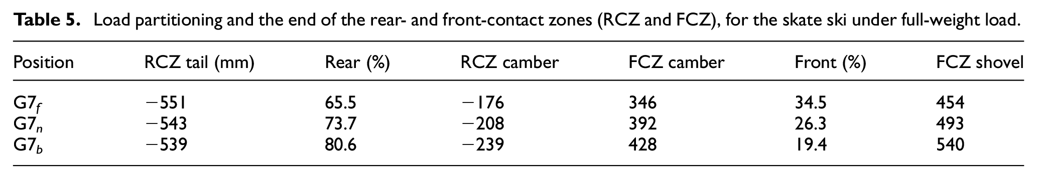
Depicted in Figure 8 are the ski-camber profiles from the skate ski loaded with full weight (70 kg), at the same loading positions as in Figure 6. Although not as large as at half-weight load, there is still a difference between the ski-camber profiles measured with the MB and the CB at full-weight load. Figure 8 also shows that the load position has a larger impact on the ski-camber profile of the skate ski, than the type of load transfer interface. However, because skate skis are stiffer, the G7 f loading position will not make the ski collapse as much as it does for the classic ski. According to equation (3), the load supported by the rear- and front-friction interfaces are listed in Table 5. By comparing the cambers at half and full-weight load, it can be seen that the length of the rear friction interface remains more or less constant at half-weight load, for the different G7 positions. At full-weight load, the length of the rear contact zone increases if the skier applies the load closer to the BP. In fact, the length is 300 mm at G7 b , 335 mm at G7 n , and 375 mm at G7 f .
Load partitioning and the end of the rear- and front-contact zones (RCZ and FCZ), for the skate ski under full-weight load.
Skis within a pair do not necessarily have the exact same ski-camber profile, however, the trends of how the second ski or a ski in general reacts to the NFL and MB are the same for all skis encountered so far. It was observed that skis deform to a larger extent when the NFL is applied closer to the BP. This is due to the load transfer interface, which differs between the CB and the MB, with the MB transferring more of the load closer to the BP, where the ski supposedly is more prone to deform. However, depending on the design of the load transfer interface between the ski boot and binding, the binding bar on the ski boot may exert a pulling force. Which was observed to increase the camber height in the front while lowering it at the rear.
Conclusions
The current study suggests that, measurements of the ski-camber profile can be influenced by the contact between the boot and ski and that this must be taken into account to attain high precision and reliability.
Starting with the measurement boot, it is concluded that the loaded interface between the contacting body and the ski influences the ski-camber profile during measurements. This is evident because using the CB results in a less collapsed ski than the MB in all the cases considered herein. Therefore, if there is a demand for higher precision and reliability of the measurements, then the contacting body should be as similar as possible as the skier’s boot.
In addition, the skier’s stance in the G7 position also influences ski-camber profile, both for the classic- and the skate ski, resulting in that the maximum camber height decreases when the athlete moves their center of mass forward. Applied in a classic skiing setting, an athlete paired with soft skis could potentially experience kick-wax contact with the snow in the G7 f position. Applied in skate skiing, the relative decrease in maximum camber height, when the athlete leans forward, is smaller (28.8%) compared to the decrease for the classic ski (67.4%). In connection to this, the different G7 positions induce a notable difference; 65.5%–93%, in load supported by the rear friction interface for the classic ski. The length of the friction interfaces is, however, only marginally affected by the G7 position under half-weight load while they exhibit a greater increase under full-weight load.
Footnotes
Notation
Acronyms
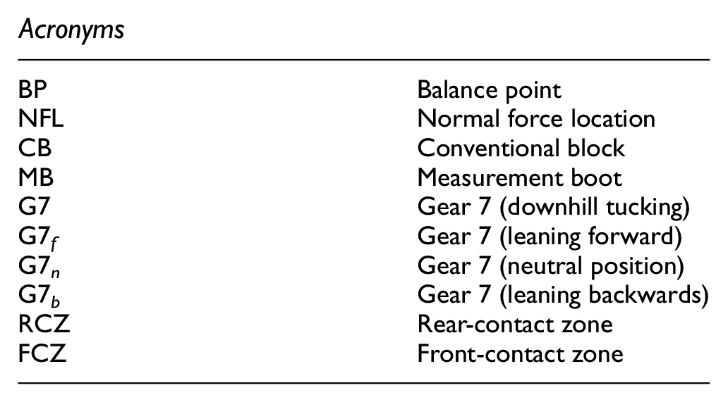
| BP | Balance point |
| NFL | Normal force location |
| CB | Conventional block |
| MB | Measurement boot |
| G7 | Gear 7 (downhill tucking) |
| G7 f | Gear 7 (leaning forward) |
| G7 n | Gear 7 (neutral position) |
| G7 b | Gear 7 (leaning backwards) |
| RCZ | Rear-contact zone |
| FCZ | Front-contact zone |
Acknowledgements
The authors would like to thank the reviewer Mr. Teemu Lemmettylä for the valuable feedback.
Declaration of conflicting interests
The author(s) declared no potential conflicts of interest with respect to the research, authorship, and/or publication of this article.
Funding
The author(s) disclosed receipt of the following financial support for the research, authorship, and/or publication of this article: The authors would like to acknowledge financial support from the Swedish Olympic Committee and from The Swedish Research Council (VR), DNR 2019-04293.