
Abstract
The wrist is a common injury site for snowboarders who often fall onto an outstretched hand. Wrist protectors are worn by some snowboarders to prevent wrist injuries by attenuating impact forces and limiting wrist extension. This paper presents a bespoke pendulum test device for impacting wrist protectors when fitted to a wrist surrogate. The rig can replicate injury risk scenarios, while measuring temporal forces and wrist extension angles. Results from testing 12 snowboarding wrist protectors are presented, including differences in peak vertical force, the time to reach this peak, and energy absorption between products. When compared to an unprotected surrogate, all 12 products lowered the peak force by at least 24% and increased the time to reach this peak by at least 1.8 times. Due to the severity of the load case employed, none of the products lowered the impact force below 2.8 kN, which is the value presented in the literature to fracture a cadaveric wrist. The developed rig could be used to support the development of new wrist protectors, as well as the development of finite element models for predicting wrist protector performance.
Introduction
Many snowboarding injuries occur to the lower arm and wrist1–6 with distal radius fractures being common.1,7 Most of these wrist injuries are reported to be due to inexperienced snowboarders 1 falling 8 forward or backward onto an outstretched hand. Loads from such falls can compress the palm and extend the wrist past its natural limit (hyperextension), causing sprains and fractures.9,10
Wrist protectors are worn by some snowboarders to prevent injuries,1,11 but it is unclear which specific design works best and limited tools exist to support manufacturers in evaluating protective performance. There are various wrist protectors on the market, which commonly include a combination of splints to prevent hyperextension and palmar padding to cushion the impact.1,11–13 Snowboarding injury surveillance data lack detail regarding protective equipment usage and design, which is thought to contribute to opposing opinions on wrist protector effectiveness in the literature. Some authors claim wrist protectors work,2,3,11,14–18 while others warn that they may transfer the load and cause different upper extremity injuries.19–21
Following a call from the snowsports safety community in 2013, 1 working group ISO/CD 20320 developed a standard for snowboard wrist protectors: ISO 20320:2020. 22 Tests in ISO 20320:202022 are driven by the need for simple and repeatable tests that can be conducted in test houses, and include a quasi-static bend test and an optional impact test. The impact test is only for products that claim to protect the palm against impact. The measured force in the impact test must be below 3 kN when a 2.5 kg guided mass (40 mm by 40 mm flat face) falls onto the palm region of the protector positioned on an anvil (3–5 J impact energy depending on protector size). The rigid hemispherical anvil used in this impact test is not representative of a wrist and has limited biofidelity. 23
Quasi-static and impact tests have also been used to find the load to fracture a cadaveric forearm, with mean values from studies between 1 and 4 kN (mean and standard deviation (SD) of 2.7 ± 0.8 kN24–37 as per Supplemental Table 1). The variation in fracture force between these studies could be due to differences in the bone mineral density, 38 sex, 39 age,40,41 and ethnicity 42 of the cadaver samples. Researchers have used various surrogates, rigs and energies to simulate wrist-surface impacts with discrepancies between studies.43–46 Finite element models of wrist protectors have also been presented,47–49 but only offer simple representations of products that are not ideal for assessing design features.
An impact rig and associated surrogate wrist for simulating injurious snowboarding falls would allow designers and manufacturers of wrist protectors to better understand the performance of their prototypes and products. Such a rig and surrogate could also support the development of finite element models for studying protector design features, 49 and provide relevant information regarding possible changes to certification tests in ISO 20320:202022 and standards for similar products (e.g. EN 14120:200350). This work presents a surrogate and bespoke pendulum test device, referred to herein as ‘the rig,’ for impacting wrist protectors when fitted to a wrist surrogate. Impact test results for 12 snowboarding wrist protectors are presented, and compared with those obtained from a quasi-static bending test.
Methods
Impact rig
Figure 1 shows the developed rig, which can deliver an impact at a speed of just over 5 m/s (depending on release height) onto the hand of a wrist surrogate. The surrogate can be impacted either without (unprotected) or with (protected) a protector. The rig was designed based on impact conditions reported by Greenwald et al. 36 when fracturing cadaveric forearms, as their work represented the most detailed cadaveric impact scenario in the literature.24–37 The research by Greenwald et al. 36 includes details of the setup (mass of 23 kg dropped from a height of 0.4 m, giving a vertical velocity of 2.8 m/s, and an energy of 90 J upon impact), fracture load (2.8 ± 0.76 kN) and crucially a typical force-time trace showing the loading rate of impact on the cadaveric forearm.
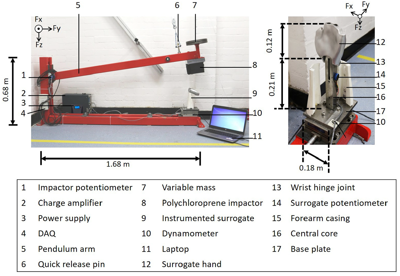
Pendulum impact test rig and detailed view of the surrogate. The variable mass shown on the end of the pendulum arm was not used for the work presented here.
For the set-up in the present study, the chassis of the rig was formed from welded steel box section (80 mm by 40 mm by 3 mm with a mass per unit length of 5.34 kg/m) supporting a 1.5 m long pendulum arm on a silver steel shaft. The shaft was mounted to the rig via bronze bushings and pillow bearings to give smooth rotational movement. The rig was rigidly fixed to a concrete floor. A pulley system was used to manually raise the pendulum arm and a pin was used to release it.
A surrogate was required to represent the wrist and mount protectors for testing. The surrogate was mounted vertically onto the rig with the hand at the top and formed of five main components: (i) a CNC machined aluminum hand (Protolabs, UK), (ii) a medium carbon steel central core (26 mm by 30 mm by 214 mm), (iii) a two-part laser sintered polyamide forearm casing (Materialise, UK), (iv) a shaft (ø12 mm by 60 mm, silver steel, RS Pro, UK) to mimic the wrist joint connecting the hand to the central core, and (v) a mild steel base plate to connect the surrogate to the rig. The surrogate was similar to the scanned surrogate used by Adams et al. 51 for quasi-static bend testing, with modifications to make it suitable for impacting.
The forearm of the participant used by Adams et al. 51 was rescanned (3dMDbody5, 3dMD,Atlanta, Georgia, USA) in a position more suitable for generating a surrogate for impact testing. Ethical approval was obtained from the Faculty of Health and Wellbeing Ethics Committee, Sheffield Hallam University, UK (HWB-S&E-69). The scan geometry was post processed (Geomagic, 3D systems, Rock Hill, South Carolina, USA) and imported into CAD software (Pro Engineer, PTC Inc, Boston, Massachusetts, USA), where the fingers and thumb were removed, the forearm was converted to a shell and a hinge joint was added to the wrist. Excluding the fingers and thumb was justified because the dorsal splints of most wrist protectors do not go past the knuckles and the fingers offer little resistance during impact hyperextending before the palm strikes the ground. 36
Instrumentation
Impact forces were measured using a three-axis dynamometer (9257A, Kistler, Winterthur, Switzerland) bolted to the base of the rig and connected to a charge amplifier (FE-128-CA, Fylde, Preston, UK). The lower end of the surrogate central core was securely fastened onto the base plate that was bolted to the dynamometer. Wrist extension angle was measured by a potentiometer (POL 200, Metallux, Rochester, New York, USA) within the central core, positioned 53 mm below the joint. The potentiometer was connected to the wrist joint shaft via a toothed timing belt. Another potentiometer (6657, Bourns, Riverside, California, USA) mounted to the pendulum shaft measured the angular displacement of the pendulum arm. A stand-alone 24-volt power source (Powergorilla power bank, Powertraveller, Alton, UK) powered both potentiometers, which were synchronized with the dynamometer and sampled into a laptop via a Data Acquisition Device (DAQ) (USB-6211, National instruments, Austin, Texas, USA). A high-speed camera (Phantom Miro Lab 320, Vision Research, Wayne, New Jersey, USA) was also synchronized with the DAQ using a Bayonet Neill Concelman (BNC) cable and manual trigger. All devices were sampled at 20 kHz with data analysis conducted using spreadsheets (Excel 2010, Microsoft, Redmond, Washington, USA).
Calibration of the dynamometer involved removing masses, while measuring voltage change. To calibrate the vertical axis (z-axis), the dynamometer was positioned face up with masses up to 250 kg removed. For the horizontal (y-axis) and lateral (x-axis) axes, the dynamometer was fixed on the horizontal side, then lateral side, with masses up to 100 kg hung and then removed. To calibrate the potentiometers, the pendulum arm and surrogate hand were held at different angles (range of 90°), as measured with an inclinometer (MW570-01, Moore & Wright, Bowers Group, Camberley, UK) to within 0.05°. When using the calibration parameters found for the potentiometers, the mean absolute difference between the measured and predicted angle was <1°.
Tuning the impact rig with the unprotected surrogate
To enable the rig to match the loading rate applied to a cadaveric forearm by Greenwald et al., 36 compliant material was added to an aluminum plate (400 mm by 120 mm by 180 mm) that was bolted to the end of the pendulum arm, as done by de Grau et al. 52 when testing helmets with a linear impactor. Impacts were conducted with the surrogate hand at maximum extension (∼110° from vertical), so the impactor struck the central core analogous to the wrist. The compliant material was selected via pilot testing of candidate materials of varying thicknesses and mass, including various grades of polychloroprene, polyurethane, and low-density polyethylene. The candidate material that gave the closest loading rate to that of Greenwald et al. 36 was a 100mm thick layer of polychloroprene Shore A hardness 50 (Boreflex Ltd., Rotherham, UK) with a density of 1450 kg/m3, tensile strength of 40 kg/cm2, and Shore A hardness of 50 ± 5, as stated on the data sheet. To create replaceable, compliant impactors (external dimensions of 100 mm by 120 mm by 160 mm), sets of five 20 mm thick polychloroprene blocks were bonded together with a rubber reinforced adhesive and then bonded to a 1 mm thick aluminum sheet that could be bolted to the aluminum plate on the pendulum arm. When fitted with a polychloroprene impactor, the pendulum arm was a few degrees above horizontal when it first contacted the unprotected surrogate.
The total mass of the pendulum arm did not contribute to an impact on the surrogate, so the effective striking mass was calculated. The effective mass of a pendulum is its moment of inertia about the pivot divided by the distance from the pivot squared.53,54 Therefore, the effective striking mass of the box section bar of the pendulum arm in isolation was taken as a third of its mass (∼2.5 kg) as calculated from the data sheet. The mass of additional attachments to the pendulum arm were also taken into account. This included mounts that totaled ∼2.0 kg to facilitate additional mass or alternative impactor setup for other applications, as well as the aluminum plate (∼2.5 kg) and polychloroprene impactor (∼2.6 kg). When added to the effective mass calculated for the bar in isolation, the total effective mass for the pendulum was ∼10 kg. The impact energy of the pendulum arm with polychloroprene was approximately 40 J when released from 0.4 m, equating to less than half the value of 90 J used by Greenwald et al. 36 for the cadaveric arm when released from the same height.
Impact testing of an unprotected surrogate
To assess the repeatability and degradation of the polychloroprene impactor, repeated impacts were conducted on the unprotected surrogate. Before testing, the polychloroprene impactor was acclimatized to 18° for 24 hours. Following acclimatization, Shore A hardness measurements were taken at 16 locations distributed around the impactor face with a durometer (AD100, Checkline, Cedarhurst, New York, USA) to within 0.1 ShA. Four repeat measurements were taken at each of the 16 locations. The polychloroprene impactor was then fitted to the rig and the pendulum arm was dropped 50 times onto the unprotected surrogate from a height of 0.4 m. The start of an impact on the unprotected surrogate was defined as the instant when the vertical force first exceeded the mean plus 10 standard deviations of the data from this channel over a 1 second window (20,000 data points) after the pendulum was released. The end of an impact was defined as the first instance when the vertical force returned to zero.
Impact testing of wrist protectors
To demonstrate the suitability of the rig to assess the performance of wrist protectors, 12 snowboarding wrist protectors were tested (See Figure 2 and Supplemental Table 2). The protectors were from 10 brands, varying in overall dimensions, location and size of splints, and size and material of any palmar padding. Four of the products were gloves with integrated protection (protective gloves). All protectors had the same strapping conditions on the surrogate. The straps were tightened using the method of Adams et al. 51 which involves hanging masses from them with the surrogate held in a horizontal position. The position of the tightened straps was marked for future reference, with the strapping tightness of the protector set before each impact using these marks.
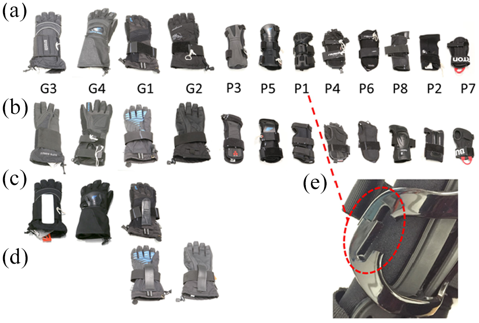
Twelve wrist protectors tested with the bespoke rig; protectors are shown from left to right in decreasing size order: (a) dorsal view of protectors, (b) palmar view of protectors, (c) exposed dorsal splints shown for G3, G4, and G1, (d) exposed palmar splints shown for G1 and G2, and (e) snapped sliding mechanism shown for P1. For (c–d) protectors are aligned vertically to (a) and (b).
Protector stiffness is related to the ability of the protector to limit wrist extension under load. More than a year before impact testing, the stiffness of the protectors was measured in a quasi-static bend test as described by Adams et al. 51 The bend test was similar to, but predated, the one in ISO 20320:2020. 22 The protector was fitted to a wrist surrogate (‘scanned’ in Adams et al. 51 ), which was then loaded slowly (angular velocity <3°/s) to extend the wrist up to 80°. The protector stiffness between wrist extensions of 35°–55° and 55°–80° was then obtained from the gradient of two straight lines fitted to the corresponding pairs of torque-angle data points. Results from this quasi-static bend test were compared to those from the pendulum impact test to determine if protector stiffness under slow loading related to impact performance.
The frictional forces acting between the polychloroprene impactor and protector during impact were reduced by putting a 1 mm thick polypropylene sheet (Direct plastics, Sheffield, UK), with a mass of 15 g, on the surface of the impactor. During impacts with the unprotected surrogate, this polypropylene sheet was not used, as no sliding occurred and it fractured during pilot testing. When testing the protected surrogate, the surrogate hand was manually extended to a ‘start’ angle of 30° ± 0.5° from vertical for all protectors. For protective gloves, the fingers were pinned back. Due to the hand being held upright when wearing the protector, the pendulum arm was approximately 4° above horizontal when the impactor first struck the protected surrogate.
To ‘condition’ the polychloroprene and establish a baseline peak force, the unprotected surrogate was impacted four times before the protectors were tested. During data collection, testing was conducted in three bouts. Each protector was impacted once per bout, followed by three impacts on the unprotected surrogate. Each protector was impacted three times (i.e. once per bout) with the protector order randomized for each bout, giving 49 impacts of the polychloroprene impactor (13 unprotected and 36 protected). A data collection error voided the first attempt to test the protectors, meaning they were impacted twice before usable results were obtained the next day. A fresh acclimatized polychloroprene impactor was used after the data collection error was found. Testing was completed over 9 hours at 18°C ± 1°C.
For the protected surrogate, the start of an impact was defined as the instant when the wrist extension angle first started to increase. A moving average filter with a window size of 31 data points (1.6 ms, selected empirically) was used to smooth the pendulum angle data. The portion of the energy absorbed by the protector relative to the unprotected surrogate was calculated by dividing the difference in rebound heights for these two cases by the release height of 0.4 m. Comparisons between protectors were made based on peak vertical force, time to reach this peak and percentage of the energy absorbed. To monitor protector degradation over the three impacts, the peak vertical force for each impact was compared for each protector.
Results
Unprotected surrogate
When replicating the drop height of 0.4 m used by Greenwald et al., 36 the loading rate (gradient (m) of a straight line fitted to force vs time trace up to 4.5 ms) on the unprotected surrogate was similar to the value on the cadaveric forearm they tested (within 25%) (Figure 3). The peak vertical force on the surrogate (∼6 kN) was approximately twice the value reported by Greenwald et al. 36 (∼3 kN), when energy would have been absorbed during fracturing of the forearm. Horizontal and lateral forces were also generated during impact (Figure 3). Inspection of a high-speed video indicated that the joint connecting the hand and forearm moved approximately −3 mm in the horizontal direction during impact, and then returned to approximately +1 mm post impact. As lateral forces were low (Figure 3), they were not considered further. Based on the pendulum rebound height, approximately half the kinetic energy upon impact with the unprotected surrogate was absorbed by the system. Energy absorbed by the system was mainly attributed to friction between the impactor and the surrogate, hysteresis of the polychloroprene under compression, and movement and vibration of the rig and surrogate.
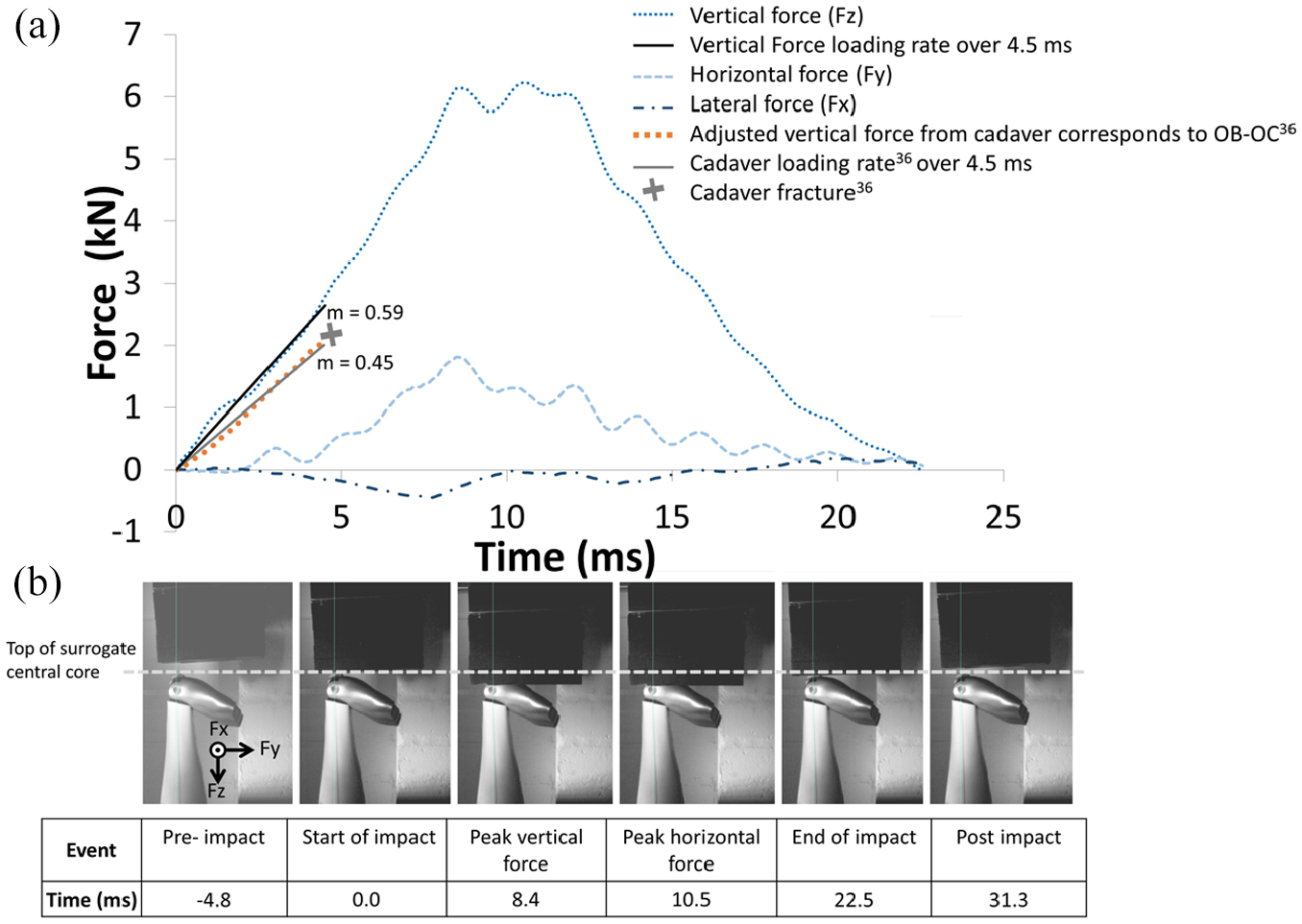
(a) Force versus time data for an impact with a release height of 0.4 m when using the polychloroprene impactor on the unprotected surrogate, with the loading curve data from Greenwald et al. 36 (dotted orange). The loading rates for vertical force for both the presented setup (solid black line) and Greenwald et al. 36 (solid gray line) over 4.5 ms are included, with gradients for both loading rates reported (where m = gradient over portion of interest kN/ms). The data from Greenwald et al. 36 was digitized from the steeper region of the force versus time data presented in Figure 7 of the article, 36 over a ~5 ms period occurring after 20 ms, for the impact on the unbraced cadaver. The digitized region corresponds approximately to that between points OB and OC, as defined in Greenwald et al. 36 The force time data from Greenwald et al. 36 has been adjusted to start at 0 s and 0 N from the point where the force was continually increasing prior to fracture to determine the loading rate. (b) High-speed video footage showing six key stages of the impact.
The first impact on the unprotected surrogate had vertical and horizontal force versus time traces that were clearly different to the other 48 measurements (the measurement for one impact was lost to a recording error). The peak vertical force for the first impact was 5.9 kN, with a higher mean for the other measurements of 6.2 ± 0.05 kN, and a range of 0.26 kN. The peak horizontal force was the same for the first impact (2.0 kN) as the mean for the other readings at 2.0 ± 0.03 kN, with a range of 0.11 kN. The coefficient of variation for peak force in the vertical and horizontal directions was <2% for all 49 impacts. When hardness measurements were repeated on the polychloroprene after 50 impacts, the mean across all locations had reduced marginally from 59 ± 1.6 to 58 ± 1.6 ShA.
Protector comparison
The 12 unprotected impacts (excluding the ‘conditioning impact’), from before the first bout and after each of the three testing bouts, had a coefficient of variation for peak force in the vertical and horizontal directions of <3.5%, which was greater than the results found for the repeatability study (coefficient of variation <2%), as presented in the previous section. The mean peak vertical and horizontal forces for these 12 unprotected impacts were similar to those in the repeatability study. The mean peak vertical force for the 12 unprotected impacts was 6.2 ± 0.10 kN, with a range of 0.33 kN. The mean peak horizontal force for the 12 unprotected impacts was 1.8 ± 0.06 kN, with a range of 0.19 kN.
The force versus wrist extension angle results in Figure 4 are typical of those from the rig, albeit with different values for each protector, and are used here to explain the general trends. Figure 4 shows results for an impact on stand-alone protector P5, which was the ‘long protector’ in Adams et al. 51 and AP7 in Schmitt et al. 55 Protector P5 was 210 mm long and 85 mm wide with almost full length thermoplastic (DuPont Hytrel®) dorsal and palmar splints (Figure 2). Shortly after the impactor struck the surrogate (t1), there was an initial spike in vertical force (t2), followed by a period with the horizontal force temporarily dominant as the wrist started to extend (t3). The horizontal force reversed direction (t4) as the wrist extended past 50°, with the vertical force steadily increasing as the wrist continued to extend. The peak vertical force occurred (t5) just before the maximum wrist extension angle (t6). After reaching the peak value, the vertical force decreased with the wrist extension angle. The vertical force returned to 0 (t7) when the impactor left the surrogate.
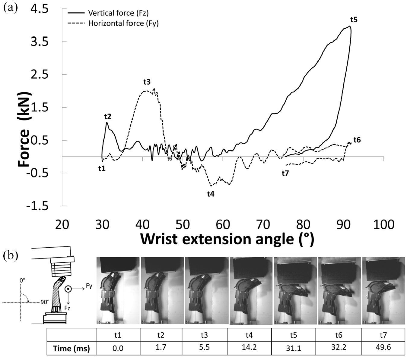
Results for an impact with a release height of 0.4 m on protector P5: (a) force and wrist extension angle versus time and (b) high-speed video images show the key phases of the impact.
Figure 5 compares results for an impact on the surrogate when unprotected and protected with protectors P5 and P7 (short protector in Adams et al. 51 AP4 in Schmitt et al. 55 and the protector modeled by Newton-Mann et al. 49 ). P7 was 160 mm long and 72 mm wide with two narrow splints on the dorsal side and three narrow splints on the palmar side, as well as a palmar pad. The splints were High Density Polyethylene (HDPE) and the palmar pad was a polyurethane foam covered with a HDPE shell 49 (Figure 2). The protectors reduced the peak vertical force on the surrogate, while extending the time to reach this peak. The peak horizontal force was higher when impacting the protected surrogate due to the sharp increase following initial contact (∼−30 ms to −25 ms in Figure 5(a)). While the force versus time relationships were similar for protectors P5 and P7 (Figure 5(a)), particularly for vertical force, clear differences were seen in their vertical force versus wrist extension angle relationships (Figure 5(b)). Similar to its longer counterpart (P5) with m = 0.13 kN/° between 60° and 90°, the vertical force for the shorter protector (P7) showed a clear increase when the wrist extension angle reached 60°, but with a two part loading curve with a shallow gradient (m = 0.04 kN/°) from ∼60° to 85°, followed by a steeper gradient to peak vertical force at approximately 95° (m = 0.26 kN/°).
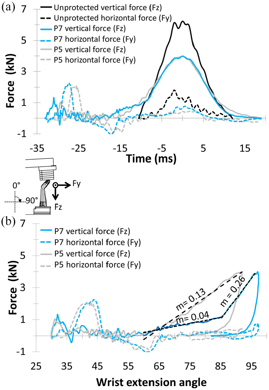
Comparison between an impact on an unprotected and protected surrogate for two protectors P5 and P7, for a pendulum release height of 0.4 m. (a) Force versus time, results are aligned with the peak vertical force at 0 s. (b) Force versus surrogate angle (unprotected case not shown as the surrogate angle does not change) where m = gradient over the portion of interest (kN/°).
The sliding mechanism on the dorsal side of protector P1 snapped under the first impact (Figure 2(e)), so it was only tested once. For 8 (73%) of the remaining 11 protectors, the lowest peak vertical force was recorded for the first impact, with 6 (54%) of these protectors recording the highest value for the last (third) impact. The largest difference in peak vertical force between impacts was for protector P2, where the values were similar for the first two impacts (∼4 kN), but increased by >20% for the third impact to almost 5 kN. For the other five cases where peak vertical force increased from the first to the last impact, the increase ranged from 1% to 7% (mean and SD of 3.6 ± 2.7%). Based on these findings, the results from the first impact were used when comparing the 12 protectors.
For two of the 12 (17%) products tested, the peak horizontal force was similar to the unprotected surrogate with a value of 1.8 kN. For the remaining 10 of the 12 (83%) products tested, the peak horizontal force was higher for impacts on the protected surrogate (range of 1.9–2.5 kN for the 10 products) than for the unprotected surrogate. When compared to the unprotected surrogate (peak vertical force = 6.2 kN with a time to peak of 10.6 ms), the peak vertical force was reduced by at least 1.5 kN and the time to peak was increased by at least 20 ms for all 12 protectors (Figure 6(a)). Greenwald et al. 36 reported that, on average, cadavers fractured at loads of 2.8 ± 0.76 kN, and none of the 12 protectors attenuated forces below this threshold. Relative to the unprotected surrogate, the 12 protectors absorbed between 17 and 37% more energy (Figure 6(b)). Some patterns were observed when comparing the performance of the 12 protectors. Products returning a lower peak vertical force tended to take longer to reach this peak, with the exception of two outliers. These outliers were the stand-alone protector – P1 (peak vertical force = 3.0 kN with a time to peak of 31 ms) that broke under the first impact and a protective glove – G2 (peak vertical force = 4.5 kN with a time to peak of 36 ms), which was the only glove without a dorsal splint (Figure 2). The gloves tended to take longer to reach peak vertical force than the stand-alone protectors. Protectors that absorbed more energy tended to have lower peak vertical forces (Figure 6(b)). Protective glove G1 appears to be an outlier (Figure 6(b)), and unlike the other gloves, it had splints on both sides and a palmar pad.
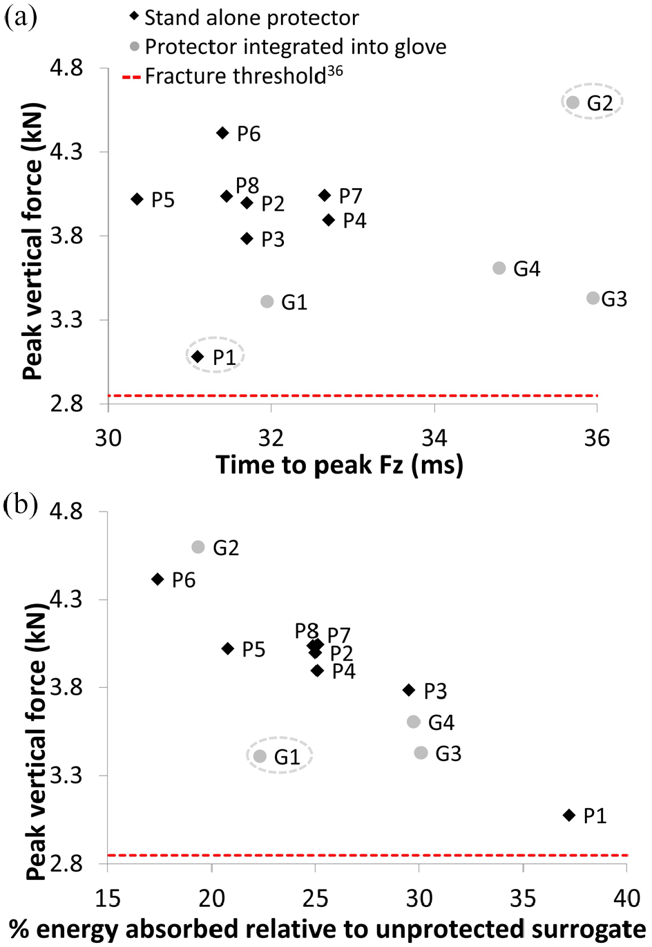
Comparison for the first impact between 12 protectors for a pendulum release height of 0.4 m: (a) peak vertical force versus time to peak and (b) peak vertical force versus % energy absorbed relative to unprotected surrogate. Outliers highlighted with dotted ellipse.
The protective gloves gave a lower peak vertical force than the stand-alone protectors with a similar quasi-static stiffness (Figure 7(a) and (b)), with the exception of one glove (G2) that was identified as an outlier for the time to reach peak vertical force (Figure 6(a)). Products with a larger quasi-static stiffness for wrist extensions of 55°–80° tended to give a lower peak vertical force under impact (Figure 7(b)). Protective gloves took longer to reach peak vertical force than the standalone protectors with a similar quasi-static stiffness (Figure 7(c) and (d)), with the exception of G1, which was identified as an outlier for energy absorption (Figure 6(b)). Protectors with a larger quasi-static stiffness tended to reach peak vertical force sooner (Figure 7(c) and d)).
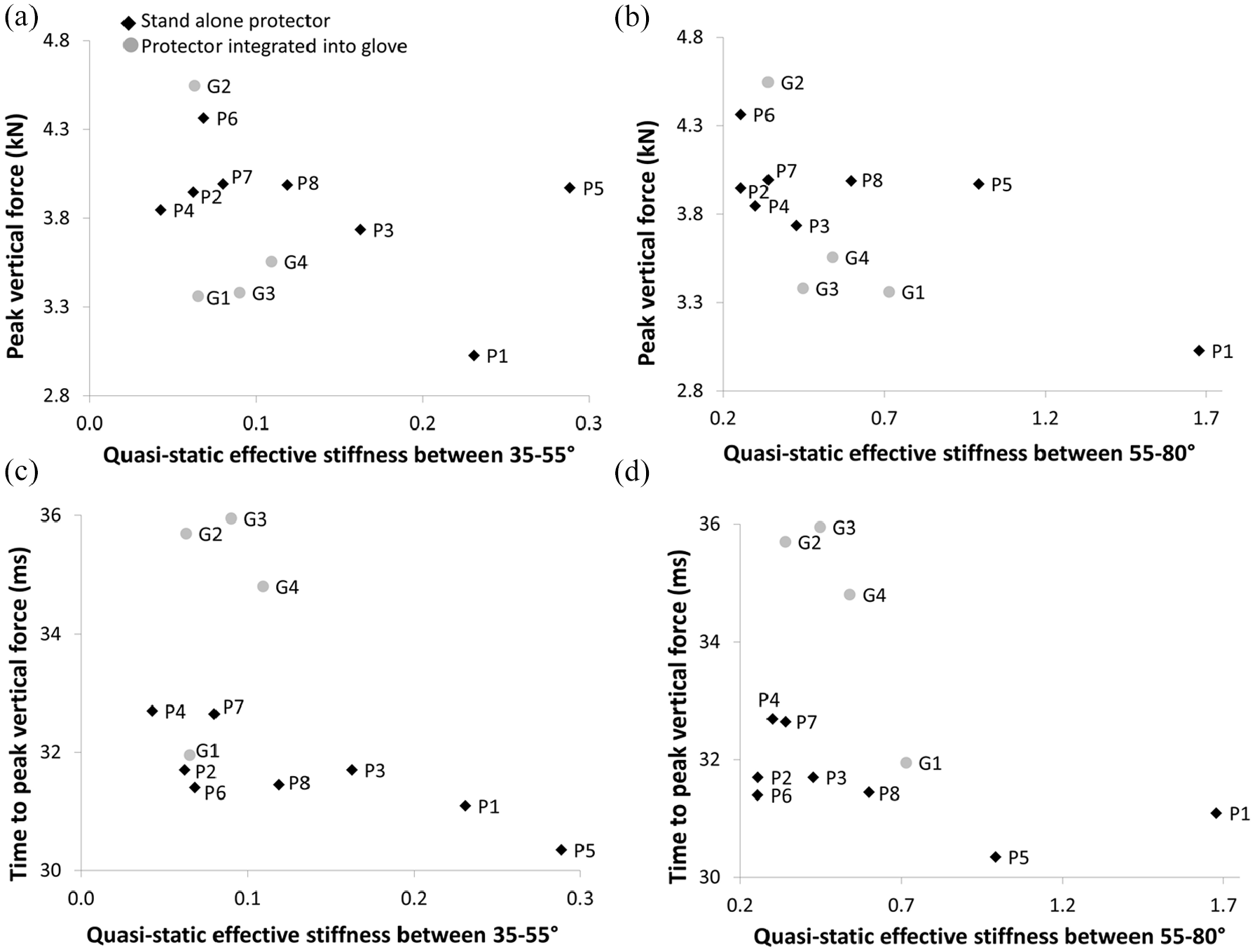
Comparison of quasi-static and impact test results: (a) peak vertical force versus quasi-static stiffness between 35° and 55°, (b) peak vertical force versus quasi-static stiffness between 55° and 80°, (c) time to peak vertical force versus quasi-static stiffness between 35° and 55°, and (d) time to peak vertical force versus quasi-static stiffness.
Discussion
A bespoke pendulum test device and instrumented surrogate to evaluate the protective performance of snowboarding wrist protectors was introduced. This rig can mimic the conditions surrounding a snowboarding fall to facilitate product development, support the development of finite element models and provide information to inform possible changes to safety standards. The rig can be used to mimic different impact scenarios with adjustments to inbound velocity, mass, and stiffness. While wrist extension angles have been reported during non-injurious snowboarding 46 and skateboarding falls, 56 the specific scenarios causing wrist fractures are not well understood. For example, a range of fracture forces (∼1–4 kN) have been reported, and various effective masses (∼2–45 kg) and inbound velocities (∼1.5–3.5 m/s) have been used during laboratory studies on cadaveric forearms.26–29,37 Therefore, the stiffness of the impactor was tuned to replicate the loading rate of Greenwald et al. 36 for a drop test on a cadaveric forearm. During repeatability testing, the polychloroprene used to tune the stiffness of the impactor showed a marginal reduction in hardness (∼1 ShA or <2%) across the surface after 50 impacts. Based on these results, following a ‘conditioning impact,’ the polychloroprene impactor was deemed suitable for at least 49 impacts without noticeable changes in peak impact force (coefficient of variation <2%) and hardness.
The rig enabled comparisons to be made between 12 protectors. When compared to an unprotected surrogate, all 12 products reduced the peak vertical force by approximately one third to one half, whilst increasing the time to reach this peak. No protector lowered the force below 2.8 kN, as reported by Greenwald et al. 36 to fracture a cadaveric wrist under a similar loading rate. This finding aligns with work on cadaveric forearms, where protectors reduced impact force, but did not prevent fractures,34,36,37 and may partially explain why snowboarders can suffer wrist injuries while wearing them. 1 The recent introduction of ISO 20320:202022 may influence the range and diversity of wrist protectors available for snowboarders to purchase and should be considered when selecting products for testing in future studies.
Relative to the unprotected surrogate, approximately 20%–40% of the kinetic energy at impact was absorbed by the protectors (Figure 6(b)), including via stretching of fabric, friction during sliding, hysteresis during compression of padding and bending of splints. Except for one product (P1), no obvious protector damage was observed during testing. Peak vertical forces were, however, lowest for the first impact for 73% of the protectors, indicating that they may have degraded with changes to padding and fatigue of splints. This finding suggests that protectors may need to be replaced after a severe fall onto the hand, even if there is no visible damage, as found for ice hockey helmets 52 and in line with general guidance for helmets. Fatigue of the splints may have also occurred under the quasi-static bend testing of the protectors before impact testing. Further work is needed to confirm if protectors do degrade during testing, with implications for product design, testing, and certification strategies.
A stand-alone protector (P1) and a protective glove (G2) were outliers in the impact test data (Figure 6(a)). The stand-alone protector gave a low peak vertical force that was reached quickly (∼3.0 kN at 31 ms), while the glove gave a high peak vertical force with a relatively long time to peak (∼4.5 kN at 36 ms). The lower force for the stand-alone protector may have been due to the failure of the sliding mechanism that would have absorbed energy as it broke, similar to an expanded foam helmet liner. More of these protectors (P1) would need to be tested to determine if this snapping was a design feature, a random occurrence, a flaw with the sample or an artifact of the test. It is unclear why the glove G2 took a relatively long time to reach a high peak vertical force, although it was the only glove without a dorsal splint, which may explain its low quasi-static stiffness (Figure 7).
Unlike G2, the other three protective gloves tended to give a lower peak vertical force than the stand-alone protectors, taking longer to reach the peak and absorbing more energy (Figure 6). The additional bulk and material of these gloves may have offered some cushioning while increasing protector-impactor friction, spreading forces over a longer duration. Schmitt et al. 55 however, did not report differences between stand-alone protectors and protective gloves when they impact tested them using the method described in EN 14120:200350 (rigid anvil and drop mass).
There appeared to be general trends between quasi-static protector stiffness and both peak vertical force and the time to reach this peak. A quasi-static bending test, 51 therefore, appears to be a suitable starting point for characterizing and certifying snowboarding wrist protectors (e.g. ISO 20320:202022). While quasi-static bending allows wrist protector stiffness to be compared simply, knowledge on how torque-angle relationships relate to wrist injuries is limited, whereas forces from an impact test can be compared to published fracture thresholds for cadaver forearms.24–30,32–37 As different surrogates were used for the quasi-static bending 51 and impact tests, future work could see if using the same surrogate improves relationships between outputs. Such work could compare outputs from an impact rig, like the one presented here, with those of both the quasi-static bending and impact test in ISO 20320:2020. 22 Ideally, such work should be conducted under both room temperature (20°C ± 2°C) and low temperature (−10°C ± 2°C) conditions, as specified in ISO 20320:2020. 22
The developed rig and surrogate were not without limitations. Due to the low friction hinge joint, the wrist was fully extended when the impactor struck the unprotected surrogate, resulting in different protected and unprotected setups. As expected, vertical forces were lower when the surrogate was protected, although horizontal forces were higher in most cases. The protector stiffened the joint and raised the hand, causing the pendulum arm to strike while slightly raised, which increased horizontal impact forces. These horizontal impact forces fluctuated as the forearm moved (∼4 mm) because a torque was applied at the base where it was mounted. The polypropylene sheet added to limit frictional forces acting between the polychloroprene impactor and the protector during impact was another difference between the unprotected and protected setups.
There are also clear differences between the experimental setup of Greenwald et al. 36 and the work presented here. As the surrogate was stiffer than the cadaver forearm tested by Greenwald et al. 36 polychloroprene was used to add compliance to the impactor. However, this modification added a few kilograms, required preconditioning and the hardness of the polychloroprene decreased when repeatedly impacted. While a leaf spring 57 could replace the polychloroprene impactor, improving the biofidelity of the surrogate is also beneficial. A soft tissue simulant on the surrogate58–64 could slow the loading rate as it deforms under impact and lowers forces, reducing reliance on a compliant impactor. Flexion and extension of the wrist joint was obtained using a low friction hinge. Improving the biofidelity of the joint would enable different injury scenarios to be studied, as fractures can be caused by ulnar-radial deviation coupled with hyperextension.25,65 Future work could use an improved, biofidelic surrogate to find the impact conditions when snowboarding wrist protectors can prevent fractures. The surrogate could also be developed to include more of the arm to help ascertain whether wrist protectors simply transfer loads and cause other injuries. To better replicate the scenarios surrounding actual snowboarding falls, the surface of the impactor could be adapted to mimic snow or ice. Altering the impactor surface would enable future studies to explore how snow conditions influence injury risk.
Differences in protector performance were noted using the developed test setup. Future work could enhance our understanding of the performance of individual protectors, considering factors like overall size, strapping conditions and splint and palmar pad dimensions and materials. The effect of fitting a glove over a stand-alone protector could also be investigated. Such work could use more impact energies and extra measurement techniques, such as pressure sensors on the surrogate58,59,64 and digital image correlation, 66 alongside finite element modeling.45,47–49 The rig could serve as a tool to check the accuracy of finite element models of wrist protectors. Such finite element models would be well suited to assess the effect on impact performance when changing materials, splint dimensions, and palmar pad dimensions.
Conclusion
This paper presents a bespoke pendulum test device and instrumented surrogate that can replicate injury risk scenarios, while measuring temporal forces and wrist extension angles. Using data from the literature, the stiffness of the rig was tuned to give a similar loading rate to an impact test on a cadaveric forearm. Results from testing 12 snowboarding wrist protectors showed differences in peak vertical force, the time to reach this peak, and energy absorption between products. Such a rig can facilitate a better understanding of the performance of prototypes and products to aid the design and development of future products.
Supplemental Material
sj-pdf-1-pip-10.1177_17543371211054752 – Supplemental material for Impact testing of snowboarding wrist protectors
Supplemental material, sj-pdf-1-pip-10.1177_17543371211054752 for Impact testing of snowboarding wrist protectors by Caroline Adams, Tom Allen, Terry Senior, David James and Nick Hamilton in Proceedings of the Institution of Mechanical Engineers, Part P: Journal of Sports Engineering and Technology
Supplemental Material
sj-pdf-2-pip-10.1177_17543371211054752 – Supplemental material for Impact testing of snowboarding wrist protectors
Supplemental material, sj-pdf-2-pip-10.1177_17543371211054752 for Impact testing of snowboarding wrist protectors by Caroline Adams, Tom Allen, Terry Senior, David James and Nick Hamilton in Proceedings of the Institution of Mechanical Engineers, Part P: Journal of Sports Engineering and Technology
Footnotes
Declaration of conflicting interests
The author(s) declared no potential conflicts of interest with respect to the research, authorship, and/or publication of this article.
Funding
The author(s) received no financial support for the research, authorship, and/or publication of this article.
Supplemental material
Supplemental material for this article is available online.
References
Supplementary Material
Please find the following supplemental material available below.
For Open Access articles published under a Creative Commons License, all supplemental material carries the same license as the article it is associated with.
For non-Open Access articles published, all supplemental material carries a non-exclusive license, and permission requests for re-use of supplemental material or any part of supplemental material shall be sent directly to the copyright owner as specified in the copyright notice associated with the article.