
Abstract
Structural heart disease (SHD) encompasses a wide range of congenital and acquired cardiac abnormalities, increasingly treated with transcatheter interventions. Echocardiography plays a crucial role in optimising these procedures, providing high-resolution imaging for pre-procedural planning, real-time guidance and post-intervention assessment. The shift from two-dimensional to advanced three/four-dimensional (3D/4D) echocardiography has significantly enhanced the visualisation of complex cardiac structures, improving procedural success and patient safety. The purpose of this review article is to provide an overview of the vital role of echocardiography in key structural heart interventions, including mitral transcatheter edge-to-edge repair, transcatheter aortic valve replacement, paravalvular leak closure, left atrial appendage occlusion and atrial septal defect closure. It highlights the integration of 3D/4D imaging and advanced Doppler techniques in refining procedural precision, optimising decision-making, and improving patient outcomes. The evolving field of interventional echocardiography continues to shape SHD management, making more minimally invasive treatments available to patients.
Keywords
Introduction
Structural heart disease (SHD), which comprises congenital and acquired abnormalities of the cardiac valves, septa and chambers, has been significantly influenced by substantial advancements in interventional cardiology. Echocardiography is now essential for planning, guiding and evaluating structural heart interventions by offering high-resolution imaging and real-time feedback which is pivotal for procedural success.
The transition from two-dimensional (2D) to three-dimensional (3D) and four-dimensional (4D) echocardiography has been a game changer, improving the ability to visualise complex cardiac structures and provide precise measurements. While 3D echocardiography provides detailed spatial visualisation of cardiac anatomy, 4D echocardiography adds the temporal dimension, enabling real-time dynamic assessment of cardiac motion and function. 3D/4D transesophageal echocardiography (3D/4D-TEE) is particularly valuable in transcatheter interventions enhancing precision, reducing fluoroscopy time and improving patient safety. 1
High radiation doses during structural procedures pose risks to both patients and catheterisation laboratory staff, including interventional cardiologists, sonographers, and imaging personnel. Echocardiography, particularly TEE, provides real-time guidance without exposing staff or patients to ionising radiation, making it a valuable tool for reducing cumulative radiation burden. This benefit is increasingly important given documented variability in radiation exposure across centres and procedures, emphasising the role of TEE in enhancing safety in contemporary structural heart interventions. 2
Beyond procedural guidance, echocardiography is increasingly utilised for pre-procedural, intra-procedural, and post-intervention monitoring. Advanced Doppler techniques provide valuable insights into cardiac function, enabling the detection of potential complications such as residual leaks, prosthetic dysfunction or changes in ventricular performance, thereby improving real-time decision-making during interventions. As these innovations continue to evolve, echocardiography will remain a key tool in advancing the field of SHD interventions. 3 The purpose of this review article is to provide an overview and to highlight the critical role of echocardiography in optimising structural heart interventions including mitral transcatheter edge-to-edge repair (TEER), transcatheter aortic valve replacement (TAVR), paravalvular leak closure (PVL), left atrial appendage occlusion (LAAO) and atrial septal defect (ASD) closure. It elucidates how advanced echocardiographic techniques such as 3D/4D echocardiography and fusion imaging enhance procedural planning, device positioning and overall patient outcomes.
Although this review provides a comprehensive discussion of echocardiography in major structural heart interventions, several emerging or less commonly performed procedures were not included, such as tricuspid and pulmonary valve interventions, coronary and cardiac fistula occlusions, valve-in-valve procedures and the use of intracardiac echocardiography. Their omission reflects the scope and focus of this review, which aims to highlight the most widely adopted structural interventions. Given the rapid evolution and growing clinical importance of these procedures, future reviews may incorporate them to provide a more complete overview of echocardiographic applications in SHD.
Mitral valve interventions
Mitral regurgitation (MR) is a prevalent valvular disease linked to increased morbidity and mortality.4,5 It affects over 2 million individuals in the United States, with a prevalence of 10% among those aged >75 years.6,7 In Europe, MR is the second leading indication for heart valve surgery. 8 Despite advancements in diagnostic and therapeutic technologies, MR remains underdiagnosed and undertreated, often leading to poor survival and quality of life. The aetiology of MR varies by region: in high-income countries, functional (secondary) MR remains the predominant aetiology, while degenerative causes such as mitral valve (MV) prolapse are more common than in low- and middle-income countries. In contrast, rheumatic heart disease continues to be a major contributor in low- and middle-income regions. Accurate assessment, particularly through detailed echocardiography, is crucial for effective management. The severity of MR should be evaluated using a multiparametric approach comprising qualitative, semi-quantitative and quantitative methods to facilitate an accurate diagnosis.
Primary MR
Primary MR results from intrinsic disease of the MV apparatus (leaflets, chords, annulus, papillary muscles). Common causes include degenerative changes, rheumatic disease, endocarditis and valvulopathies induced by radiation or drugs. Degenerative MR is the most common form, with two main phenotypes. The first, fibro-elastic deficiency is usually characterised by single chordal rupture and isolated scallop prolapse (typically P2) and affects patients >60 years. The second, Barlow’s disease9,10 involves excess, thickened leaflet tissue with redundant chordae. It usually affects younger patients (40–60 years) and often involves multiple scallops.
However, when we refer to primary MR, MV prolapse (MVP) is the most common condition. MVP is defined as leaflet excursion >2 mm above the annular plane, and it is easily diagnosed through echocardiography, 11 particularly 3D/4D-TEE. 12 3D/4D-TEE provides an ‘en-face/surgeon’s view’ of the valve offering anatomic details essential for the interventionists. These include identifying prolapsing scallops, detecting indentations or cleft MV, assessing mitral annular disjunction 13 and evaluating suitability for transcatheter treatment.
Secondary MR
Secondary (functional) MR (FMR) arises from altered left ventricular (LV) and/or left atrial (LA) geometry and function, with the valve itself remaining structurally normal. Common causes include ischaemic or non-ischaemic cardiomyopathy and atrial myopathy (e.g. due to atrial fibrillation (AF) and LA enlargement). Restricted systolic leaflet mobility in secondary MR results from global or segmental LV remodelling, displacement of the papillary muscles and increased tethering forces that eventually lead to tethering of the leaflets.14–16
Assessment of FMR requires a thorough echocardiographic evaluation. First, LV systolic function and the left-sided chambers, including LV and LA volumes, should be assessed. Next, the mitral annulus size and leaflet motion are evaluated. Key quantitative parameters – such as vena contracta width, effective regurgitant orifice area, regurgitant volume and Doppler flow patterns – should also be measured. Finally, tricuspid regurgitation and pulmonary pressures should be assessed to complete the evaluation. 17 FMR has a dynamic component influenced by blood pressure, and it significantly leads to worse outcomes compared to primary MR with similar severity. FMR can be easily underestimated with standard 2D techniques since the regurgitant orifice is usually elliptical. 18 The addition of 3D vena contracta area (3D-VCA) measurement can overcome the limitations of 2D echocardiography and provide a more accurate assessment of MR severity.
Transcatheter treatment of MR
Nearly 50% of patients with MR are not suitable candidates for surgical intervention due to advanced age, comorbidities or severely reduced ejection fraction (EF). This unmet clinical need has driven the development and adoption of transcatheter therapies, which have significantly expanded treatment options for these patients. 19 Over the past two decades, advancements in device technology and the expertise of interventional cardiologists have made minimally invasive approaches a cornerstone in managing MV diseases. Central to these procedures is the ‘heart team’ approach, whereby echocardiography plays a critical role. This has given rise to the specialised field of ‘interventional echocardiography’, with experts often referred to as ‘structural heart disease imagers’. 20
Transcatheter devices are designed either to repair the leaflets and annulus or to replace the MV. Each device requires specific echocardiographic protocols for pre-procedural planning and intraoperative guidance. However, most common practice suggests leaflet repair through approximation with an ‘Alfieri Stitch-like’ method. Currently, two devices are commercially available for TEER – MitraClip (Abbott Cardiovascular, Abbott Park, IL, USA)21,22 and PASCAL (Edwards Lifesciences, Irvine, CA, USA).23,24 MitraClip was the first device implanted with over 150,000 to date.
Pre-procedural planning
A comprehensive pre-procedural echocardiographic evaluation is essential to determine the mechanism of MR and the anatomic suitability for TEER. 25 The MV apparatus should be thoroughly examined to assess leaflet mobility, thickness, length, the maximum flail gap distance, pathology location (central vs non-central) and the presence of leaflet or annular calcium. The mitral valve area (MVA) should ideally be ⩾4.0 cm² or at least >3 cm2, measured via 2D planimetry in the parasternal short-axis view or ideally using multiplanar reconstruction (MPR) of a 3D/4D dataset (Figure 1). Other important echocardiographic features that should be addressed when screening a patient are: baseline mitral inflow mean gradient (ideally <4 mmHg), length of the posterior leaflet (ideally >7 mm), presence of rheumatic MV disease and exclusion of left atrial appendage (LAA) thrombus. The presence of rheumatic MV disease and LAA thrombus are both absolute contraindications for TEER. According to the EVEREST trial criteria, the relative contraindications are as follows: left ventricular ejection fraction (LVEF) <25%, left ventricular end-systolic diameter (LVESD) >55 mm, flail gap >10 mm, flail width >15 mm, coaptation depth >10 mm and coaptation length <2 mm. However, with extensive clinical experience and insight derived over the years, TEER is now considered feasible with more complex anatomy. For example, even though A2–P2 are the optimal scallops for TEER, commissural prolapse can nowadays be successfully repaired using this method. 26

3D-TEE for assessment of suitability criteria for mitral-TEER. (a) 3D/4D en-face view of MV of both atrial and ventricular side with dual crop mode. (b) Biplane 2D TEE colour Doppler imaging is performed using the bicommissural view of the MV (typically acquired at 50°–70°) as the primary image (displayed on the left) and the orthogonal view (displayed on the right), demonstrating severe MR. (c) Biplane 2D TEE imaging is performed using the bicommissural view of the MV as the primary image (displayed on the left) and the orthogonal view (displayed on the right), allowing precise measurement of the posterior leaflet length. (d) Multiplanar reconstruction for MV area assessment with 3D/4D-TEE.
In addition to anatomic suitability for TEER, the ‘heart team’ must collectively deem each patient clinically suitable for TEER. According to the ESC guidelines, 18 primary MR should be treated with TEER when the patient is inoperable or at high-surgical risk with a Class IIa indication. Secondary MR requires a comprehensive multidisciplinary assessment and holistic evaluation of the patient, but recent guideline updates have applied a class Ia recommendation for treating functional ventricular MR with TEER for those who are suitable. It is relatively well known that the presence of severe FMR bodes concerningly with regard to prognosis, especially in patients with a reduced EF. Recently published randomised trials like COAPT 27 and RESHAPE-HF228,29 demonstrated a substantial clinical benefit in the group of patients that received MitraClip with a significant reduction of deaths and hospitalisations. The MATTERHORN trial 30 further elucidated a favourable safety profile for the patients with FMR that were treated with TEER rather than surgical replacement. Moreover, there have been some COAPT-like profile echocardiographic criteria incorporated in the guidelines, ultimately helping clinicians better understand which particular patient may therefore benefit from this method.
Intra-operative guidance
Procedural echocardiographic guidance involves several critical steps beginning with the transseptal puncture. This step requires precise imaging to select a superior and posterior puncture site approximately 4 cm from the mitral annulus, as measured at mid-systole in the four-chamber view (0°). Biplane imaging, with views of the aortic valve as an anterior landmark and the bicaval view at 90°–110°, helps ensure accurate localisation. After puncturing the septum, the guidewire is advanced into the left upper pulmonary vein while avoiding the LAA to prevent perforation (Figure 2).

(a) Biplane 2D TEE imaging for transseptal puncture with tenting of the atrial septum as the primary image (displayed on the left) and the orthogonal view (displayed on the right), (b) height of the septal tenting to the MV annulus level, (c) 2D and volume rendered views of the guidewire entering the left upper pulmonary vein, (d) volume render views of PASCAL device into the LA, (e) biplane 2D imaging with commissural and long-axis view for guiding the device towards the MV and (f) volume rendered view with the arms of the device open in order to check perpendicularity.
The device (MitraClip/PASCAL) is then introduced via a steerable guiding catheter and flexed inferiorly and medially towards the MV. During this stage, care must be taken to avoid injuring the ligament of Marshall, free wall of the LA or the Coumadin ridge. The ligament of Marshall runs along the epicardial surface of the LA, adjacent to the Coumadin ridge, and its proximity is important to avoid inadvertent trauma during device manipulation. As the device turns toward the valve, biplane mode showing of the commissural and long-axis (LAX) views are used to guide the operator in both lateral–medial and anterior–posterior orientations, respectively. The commissural and long-axis biplane views are particularly important for tracking the device’s location and ensuring precise positioning over the region of interest, such as a prolapsing segment or the origin of a colour jet. 3D/4D en-face views of the MV are critical for ensuring the device’s perpendicular alignment, with the arms opened perpendicular to the coaptation line. The device enters the left ventricle by closing the arms while crossing the mitral leaflets and reopening them just below the coaptation point. Crossing the valve perpendicular to the coaptation line is crucial to prevent valve distortion and ensure proper device attachment after deployment (Figure 2).
Finally, the clip is implanted by grasping the anterior and posterior leaflet, with the device arms visualised in the LAX view (135°) with biplane imaging. Before releasing the device, it is essential to confirm adequate leaflet insertion by scanning both sides of the device in the commissural view (MPR and trans-gastric extra views may also help) and also confirming adequate tissue bridge formation using the 3D/4D en-face view. Measuring the mean trans-mitral gradient is essential with a mean gradient <5 mmHg desired to avoid significant mitral stenosis 26 (Figure 3).
(a) Grasping of anterior and posterior leaflet in long-axis view, (b) transgastric view showing the ‘figure of 8’ after grasping of both leaflets, (c) implantation of a second device using biplane imaging, (d) 3D/4D en-face volume rendered view of MV showing the presence of two devices in A2–P2 scallop, (e) mean mitral-inflow gradient for final assessment of the procedure and (f) 3D multiplanar reconstruction for assessment of the remaining MV area.
Post-procedural assessment
Post-procedural evaluation confirms the success of the intervention and identifies potential complications. Colour Doppler imaging in the commissural view is the preferred method for assessing immediate MR reduction while continuous wave Doppler excludes significant MV stenosis. A mean diastolic gradient >5 mmHg at a normal heart rate indicates that the device should not be deployed. Residual MVA can be assessed using 3D/4D planimetry. Systemic blood pressure should be maintained above 100 mmHg to avoid underestimating residual MR. Previous publications have highlighted that an achievement of final post-procedural MR of less than moderate severity with a mean gradient of less than 5 mmHg is a good prognostic marker for patients in the long term. 31 While these are the desired goals with TEER in every patient, it may not be feasible especially when we encounter extreme cases including but not limited to stenotic valves, commissural prolapse or Barlow’s disease. The final result should be evaluated on an individual basis.
Finally, the size and direction of residual ASD shunting is also documented. A left-to-right shunt is expected, but if a right-to-left shunt with subsequent desaturation is observed, percutaneous closure may be necessary. Potential complications of TEER include thrombus formation on guidewires or sheaths, entanglement of the MitraClip in the chordae tendineae, leaflet rupture or perforation and a pericardial effusion with or without tamponade (Figure 4). Meticulous TEE monitoring throughout the procedure is crucial to prevent, recognise and manage these complications early and effectively.32,33

Case of leaflet tear after MitraClip implantation: (a) Tear of the posterior leaflet from the medial clip demonstrated in the 3D/4D en-face view of MV and (b) severe recurrent MR demonstrated with biplane imaging. Recurrent MR in a case with dilated cardiomyopathy and further annular dilatation: (c) biplane 2D images of two clips in the A2–P2 scallop and (d) 3D colour with multiplanar reconstruction showing recurrent MR from both sides of the clips.
Transcatheter aortic valve replacement
Aortic stenosis (AS) represents a significant cardiovascular disease that predominantly affects older adults. It is characterised by the narrowing of the aortic valve (AV), which results in restricted blood flow from the LV to the aorta leading to symptomatic heart failure, reduced cardiac output and increased morbidity and mortality. 34 Historically the gold standard treatment for symptomatic severe AS has been surgical aortic valve replacement; however, the advent of TAVR has revolutionised the treatment of patients with symptomatic severe AS – particularly those who are at high or intermediate surgical risk. 35
TAVR, first introduced in 2002, has significantly evolved in terms of device design, procedural techniques and patient selection criteria. The U.S. Food and Drug Administration (FDA) granted its first commercial approval for the procedure in November 2011, initially for patients with severe AS who were deemed ineligible for open-heart surgery.36,37 The success of TAVR is multifactorial, heavily influenced by factors such as correct valve positioning, the absence of significant complications and optimal haemodynamic performance post-deployment. Procedural success directly impacts patient outcomes including survival, functional recovery and overall quality of life. 38 Given the complex interplay of patient characteristics, procedural aspects and device-specific factors, it is crucial to optimise each of these elements to maximise success.
Defining procedural success in TAVR
Procedural success in TAVR is defined by multiple criteria including successful deployment of the valve, absence of significant paravalvular regurgitation, no need for emergency surgery and freedom from major complications. 39 Optimal valve positioning is critical as malpositioning can lead to PVL, coronary obstruction or even valve embolisation, all of which adversely impact patient outcomes. 40
Operator experience is a key determinant of procedural success. Studies have demonstrated a clear learning curve associated with TAVR, with centres and operators performing higher volumes demonstrating significantly lower rates of complications and better overall outcomes. 41 This underscores the importance of specialised training and institutional experience in achieving optimal procedural results.
Device type and delivery system are also critical factors. The evolution from first-generation to second- and third-generation TAVR devices have resulted in improved outcomes, primarily due to enhanced valve anchoring mechanisms, reduced profile of delivery catheters, and improved sealing capabilities. 42 The availability of different valve types, including balloon-expandable and self-expanding valves, enables greater precision with regard to device selection based on anatomical considerations.
Patient characteristics including aortic root anatomy, the extent of calcification and peripheral vasculature significantly influence procedural success. Complex anatomical features, such as bicuspid valves or severe annular calcification, present distinct challenges that demand thorough preoperative planning and the use of specialised techniques to ensure successful valve deployment. 43
Role of computed tomography and echocardiography in TAVR planning
Pre-procedural imaging is a cornerstone in the optimisation of TAVR outcomes. Two primary imaging modalities computed tomography angiography (CTA) and echocardiography play a fundamental role in patient selection, procedural planning and intraoperative guidance.44–46
CTA is considered the gold standard for pre-procedural planning in TAVR. It offers a detailed 3D evaluation of the aortic annulus, left ventricular outflow tract (LVOT) and aortic root. Using advanced post-processing techniques, CTA provides accurate measurements of annular dimensions and the distribution of leaflet calcification. These data are essential for selecting the most suitable prosthesis size as undersizing can lead to paravalvular regurgitation and oversizing may increase the risk of annular rupture.44,45
Furthermore, CTA is pivotal in predicting potential coronary obstruction by assessing the height and location of coronary arteries in relation to the aortic annulus. Peripheral vascular assessment is crucial in determining the feasibility of a transfemoral approach by identifying significant atherosclerosis, vessel tortuosity and the minimal luminal diameter needed for sheath insertion. 45
Advanced image reconstruction techniques such as multiplanar reformatting and 3D volume rendering facilitate the determination of optimal fluoroscopic angles for valve deployment, improving accuracy and minimising radiation exposure. 46
Transthoracic echocardiography (TTE) serves as an initial screening tool for evaluating AS severity and LV function. TEE, particularly with 3D/4D imaging, provides detailed visualisation of valve morphology, aortic root and LVOT dimensions. 3D/4D-TEE is particularly useful in patients with contraindications to CTA or when additional haemodynamic data is needed to guide decision-making (Figure 5). 47

Assessment of the annular morphology using advanced imaging techniques in the same patient. (a) En-face view generated through automated Siemens software, with the ability to make manual adjustments for hinge point definition. (b) Multiplanar reconstruction using 3D TEE (GE) demonstrates that the annulus is non-circular and dynamically changes throughout the cardiac cycle. This process, which mirrors the technique used in CT scan assessments (c and d), requires 3D data acquisition and is largely semi-automated, providing accurate annulus sizing.
Studies have demonstrated that 3D/4D-TEE offers superior accuracy in annular sizing compared to traditional 2D methods. This precision helps in reducing the risk of device mismatch and PVLs. For instance, one study found that 3D/4D-TEE measurements provided more accurate annular sizing than 2D-TEE, especially in patients where contrast-enhanced CTA was contraindicated. 48
Furthermore, 3D/4D echocardiography offers highly accurate visualisation of the LVOT including its size, shape and alignment with the aortic annulus. This comprehensive assessment is vital for selecting the most appropriate approach for valve implantation and anticipating any potential procedural challenges. Research has shown that 3D/4D echocardiography is effective in evaluating LVOT eccentricity and other anatomical variations, ultimately contributing to improved procedural success. 49
Advanced 3D/4D techniques allow for a more comprehensive and accurate assessment of the leaflet morphology including the detection of calcification and other abnormalities. Identifying these features is essential, as they can influence valve deployment and may lead to procedural complications. Incorporating 3D/4D echocardiography into the pre-procedural assessment and intra-procedural guidance for TAVR enhances the precision of anatomical evaluations, facilitates optimal device selection and improves overall patient outcomes.
Intraoperative guidance
Fluoroscopy remains the primary imaging modality during TAVR deployment; however, its use varies between centres and countries. Many centres continue to rely on echocardiography, including both TTE and TEE, for procedural guidance in a substantial proportion of patients. In addition, real-time CT-fluoroscopy fusion imaging has emerged as a valuable complementary tool, superimposing pre-procedural CT-derived anatomical landmarks onto live fluoroscopy to guide optimal implantation depth, reduce malpositioning risks and enhance procedural precision. 50
TEE provides real-time functional assessment of the implanted prosthesis. It is particularly useful for detecting immediate complications such as PVLs, valve malapposition or embolisation. Doppler echocardiography enables the assessment of transvalvular gradients and LVOT obstruction, facilitating immediate corrective actions if necessary. 50
CT imaging is increasingly utilised for evaluating valve thrombosis, leaflet motion abnormalities and structural integrity of the implanted valve. Hypo-attenuated leaflet thickening and hypo-attenuated leaflet motion can be identified early with CT, allowing timely intervention and anticoagulation therapy when necessary.47–50
Complications and their impact on clinical outcomes
Complications such as PVL have a profound impact on outcomes. Moderate or severe PVL has been associated with increased long-term mortality, necessitating advances in valve design and deployment techniques to minimise its incidence. 51 Third-generation TAVR devices with sealing skirts have significantly reduced the rates of moderate-to-severe PVL compared to earlier devices. 52
Conduction disturbances and the subsequent need for permanent pacemaker implantation (PPI) are also common complications, particularly with self-expanding valves. 53 The need for PPI can negatively impact recovery and long-term outcomes, as it may impair LV function and increase the risk of heart failure. 54 Strategies to minimise conduction disturbances include careful pre-procedural planning, precise valve positioning and individualised device selection.
Vascular complications are another major concern, especially in patients with challenging peripheral vasculature. Minimising vascular complications is essential for reducing early mortality, improving procedural outcomes and reducing hospital length of stay. The use of percutaneous closure devices and lower-profile delivery systems has played a significant role in reducing the incidence of major vascular complications. 55
The prompt identification and management of complications using imaging techniques are essential for reducing procedural mortality and enhancing patient outcomes.
Future perspectives in TAVR
The field of TAVR is rapidly evolving with technological innovations focusing on improving valve durability, reducing complications and expanding the patient population that can benefit from the procedure. Next-generation valves are being designed with enhanced features to minimise PVL, reduce the risk of coronary obstruction and improve ease of use during deployment. 56
The expanding indications for TAVR are also noteworthy. Initially approved for high-risk patients, TAVR has now been shown to be effective in intermediate- and low-risk patients, suggesting that it may become the standard of care for a broader range of patients with AS.57,58
The integration of multimodality imaging, particularly 3D/4D-TEE and CTA, has significantly enhanced the safety and efficacy profile of TAVR. These imaging techniques not only facilitate accurate procedural planning and execution but also contribute to improved long-term outcomes by enabling early detection of complications. As TAVR expands to younger and lower-risk populations, the continued evolution of imaging strategies will be critical in further optimising patient selection and guiding procedural success.
Paravalvular leak closure
A frequent complication associated with valve replacements, whether surgical or transcatheter, is PVL, irrespective of valve position. PVL is a regurgitant jet that occurs through a permanent defect between the prosthetic valve and native annulus or between the prostheses in the case of valve-in-valve. It is found in 7%–17% of mitral surgical prostheses and 5%–10% of aortic surgical prostheses.57,59 Mechanical valves tend to have higher rates of PVL than bioprosthetic valves. 60
Several factors predispose to PVL including tissue friability, infection or significant annular calcification. While most defects are small and asymptomatic, larger leaks may clinically manifest with heart failure or anaemia secondary to haemolysis in 1%–3% of patients. This is associated with worse outcomes and, therefore, makes an interventional approach to close these leaks very important. 61
While surgical repair has been the standard, recently transcatheter PVL closure has emerged as an alternative therapy to repeat surgery with similar clinical outcomes. Accordingly, they have been endorsed by the American College of Cardiology/American Heart Association and European Society of Cardiology guidelines for patients with high or prohibitive surgical risk; transcatheter repair at an experienced centre is recommended.62,63
Echocardiography (particularly 3D/4D-TEE) is the cornerstone of evaluating PVLs as it aids in the assessment of their anatomical, functional and haemodynamic impact. Consequently, it therefore assists in patient selection, evaluation and procedural strategy selection for PVL closure.
Echocardiography guides every stage of the PVL closure procedure including pre-procedural planning and device selection. Intra-procedural guidance with 3D/4D-TEE ensures accurate defect crossing, device deployment and leak reduction while avoiding complications. Post-procedurally, echocardiography helps to confirm the success of the closure, evaluate residual leaks and assess overall valve function.
Grading of paravalvular regurgitation
Echocardiographic quantification of the severity of regurgitation is essential for selecting candidates who would benefit from intervention. Assessment and quantification of PVL grade is challenging as most guidelines and consensus statements used the three-class grading system (mild, moderate, severe). This is still the most widely utilised grading system for MV PVLs as demonstrated in Table 1.59,64 For an assessment of TAVR and para-AV leaks, the three-class grading system (mild, moderate, severe) or the angiographic four-class system can be used. It is important to recognise that when assessing for PVL severity, intermediate grades may not be accurately evaluated. 65 As a result, a five-class classification for aortic PVL can be used and is shown in Table 2. 66 This comprehensive classification system establishes a framework for the systematic examination of PVL outcomes, and it can also facilitate a direct correlative assessment with outcomes derived from prior grading systems.
Echocardiographic parameters to assess the degree of PVL for MV prostheses. 59

EROA, effective regurgitant orifice area; LA, left atrial; LV, left ventricle; MV, mitral valve; MVPR, mitral valve paravalvular regurgitation; PASP, pulmonary artery systolic pressure; PVL, paravalvular leak; RV, right ventricle; RVol, regurgitant volume.
Scheme, modalities, parameters and criteria for grading the severity of aortic PVR. 59
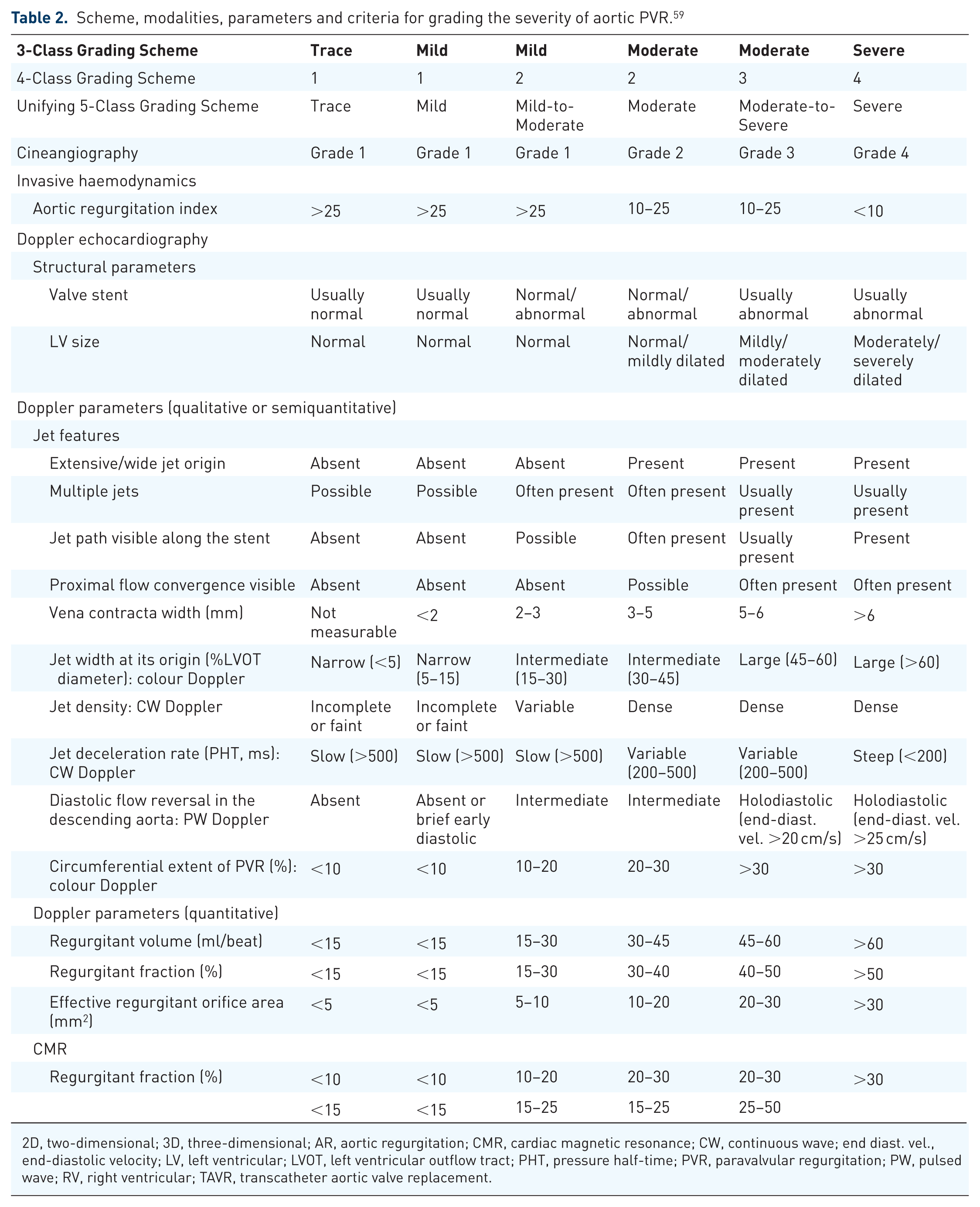
2D, two-dimensional; 3D, three-dimensional; AR, aortic regurgitation; CMR, cardiac magnetic resonance; CW, continuous wave; end diast. vel., end-diastolic velocity; LV, left ventricular; LVOT, left ventricular outflow tract; PHT, pressure half-time; PVR, paravalvular regurgitation; PW, pulsed wave; RV, right ventricular; TAVR, transcatheter aortic valve replacement.
These tables include the following parameters: 2D of the valve motion and stability, chamber size (LA, LV and RV), colour Doppler, pulsed wave and continuous wave Doppler and qualitative and quantitative Doppler regurgitation parameters. However, echocardiographic assessment has important limitations. The complex geometry of the implanted valve and surrounding structures can distort imaging planes, making measurements less reliable. Multiple and eccentric jets are common, further complicating quantification, and parameters such as vena contracta, regurgitant volume and circumferential extent of the jet may be misleading or not measurable. 67
Furthermore, high-velocity regurgitant jets detected by Doppler echocardiography are associated with shear stress, contributing to haemolysis. 9
Direct planimetry of the VCA can be obtained through an offline analysis with 3D/4D colour imaging. Doppler volumes help with deriving the planimetry of the PVL VCA and thereby enabling the measurement of the regurgitant jet dimensions. A major diameter of 3D colour ⩾0.65 cm indicates a severity level of mitral PVL, which is greater than moderate. 68 Recent studies suggest that the cut-off for 3D VCA that best correlates with severe AR is approximately 0.30 cm²; however, this threshold has not been validated for paravalvular AR. 69
Paravalvular leak size, location and morphology
The size and location of the defects aids in determining the type and size of the device and also determines the best access approach (either transseptal, transapical or retrograde aortic approach).
The evaluation protocol of PVL includes:
Precise location of the defect(s) described using a clock-face notation, 61 as shown in Figure 6, taken from a surgical view. This helps to denote the location, especially with MV PVLs or a 3D/4D en-face view of the AV from the aortic side, where the clock-face annotation shows the anterior right coronary sinus region at 12 o’clock;
The exact radial and circumferential measurements of the defects, along with the VCA;
The positioning of the defect concerning the sewing ring and prosthetic valve occluders or leaflets; and
The alignment of subvalvular structures.
While 2D imaging effectively identifies defects and assesses radial dimensions, the circumferential extent of the defect is optimally visualised using 3D/4D-TEE. 70 3D/4D-TEE also determines the leak morphology, which may present as crescent-shaped or irregular defects and accordingly determines the feasibility of closure using available devices.

(a) A 3D image representation of the surgical view of a standard mechanical prosthetic mitral valve. The clock-face annotation is illustrated. The AV is positioned at 12 o’clock, while the atrial septum is located between 2 and 5 o’clock. (b) Three-dimensional en-face representation of a prosthetic AV from the aortic perspective. The clock-face annotation indicates the anterior right coronary sinus region at 12 o’clock, the left coronary sinus region between 3 and 6 o’clock, and the noncoronary sinus region between 6 and 9 o’clock.
Another benefit of 3D/4D-TEE is its ability to detect multiple leaks, which become more noticeable after TAVR.
Device selection and planning
The choice of closure device is a critical component of pre-procedural planning and mostly depends on the size and anatomy of the PVL. Therefore, based on the data collected regarding PVL size, morphology and location, the closure device type and size are subsequently decided. Various devices are currently available aiming to safely close the leak while preserving the functionality of the prosthetic valve leaflets. The first device specifically designed for PVL closure is the Occlutech Paravalvular Leak Device (PLD; Occlutech, GmbH, Jena, Germany). Consequently, self-expanding occluder devices are often utilised off-label based on the patient’ anatomy. Most commonly, these include Amplatzer (Abbott Cardiovascular) devices such as the Amplatzer Vascular Plug (AVP) series (AVP II, AVP III and AVP IV), the Amplatzer Duct Occluder (ADO I and ADO II), the Amplatzer Atrial Septal Occluder (ASO) and the Amplatzer Muscular Ventricular Septal Defect occluder (AMVSDO). All of these devices share a common feature – they are deployed by unsheathing two discs positioned on either side of the PVL. In some cases, a single device may not fully seal the defect, necessitating the use of multiple devices. 71
Intraprocedural role of echocardiography in paravalvular leak closure
Intra-procedural guidance is key for the successful closure of PVLs, with the use of 3D/4D-TEE being a Class I recommendation in the 2020 ACC/AHA Valvular Heart Disease guidelines. 63
The use of 3D/4D-TEE during the PVL closure procedure helps with:
Guidance in vascular access by confirming the proper route (e.g. transfemoral, transapical or transseptal) to access the defect.
Real-time assessment of transseptal puncture (in case of MV PVLs using the antegrade approach).
Real-time imaging ensures that guidewires and catheters cross the paravalvular defect correctly without damaging adjacent structures.
Real-time monitoring of device final positioning and deployment (Figure 7). Assessment of valve function and leaflet motion after device deployment. Once the closure device is deployed, a gentle tug test is performed to ensure device stability. 72
Evaluation and quantification of residual leak post-deployment using 3D/4D colour Doppler.
Detection of complications post-device deployment like mechanical valve obstruction, device embolisation and coronary artery obstruction (aortic PVLs due to device protrusion). Pericardial effusion or tamponade can be caused by wire or device manipulation. Thrombus formation is also a possibility. Mechanical valve obstruction is uncommon and may be identified before the final release of the device. If obstruction of the mechanical valve occurs prior to final release, the device may be re-sheathed, repositioned or even removed. Device downsizing or re-evaluation for surgical repair may be considered. 72

Intraprocedural 3D/4D transesophageal echocardiography guidance during paravalvular leak closure of the MV. (a) The device is positioned within the paravalvular leak to assess interference with leaflet mobility. (b) The device remains in place after deployment at 7–8 o’clock.
Left atrial appendage occlusion
Patient selection and evaluation
AF is the most common arrhythmia worldwide affecting up to 8% of those above the age of 75 years with increasing prevalence. Age and comorbidity increase the risk of thromboembolism associated with AF necessitating the use of oral anticoagulant therapy. 73 The LAA is the most common site of intracardiac thrombus formation in AF with 91% of thrombi detected in those with non-valvular/non-rheumatic AF and 57% in valvular/rheumatic AF. 74 A number of randomised control studies have demonstrated non-inferiority of LAAO devices compared to oral anticoagulant therapy. This therefore provides an alternative method of thromboembolism prophylaxis for patients intolerant to anticoagulant therapy.74,75 The most commonly used devices include the Watchman (Boston Scientific, Marlborough, MA, USA), and the Amulet (Abbott Park, IL, USA).
TEE assessment of LAA anatomy is essential to determine exact size and morphology in patients being considered for LAAO. The LAA is a complex structure arising from the anterolateral area of the LA projecting outwards with varying anatomic variations including windsock, cauliflower, cactus and chicken wing morphologies. 76 The variations pose challenges for procedural deployment of LAAO devices, particularly the chicken wing morphology due to its broad orifical width and shallow depth. It is, however, associated with the lowest risk of thromboembolism. The more proximal LAA begins with an ovoid orifice and then opens into the neck, body and apex at the deepest point. 77 The orifice and landing zone, in particular, requires careful echocardiographic assessment and measurement to determine the major and minor diameters. These dimensions can be accurately measured either by 2D-TEE or 3D MPR. 78 There is also evidence that complementary imaging by CT can assist in delineating LAA anatomy particularly in cases of multiple lobes and measurements of the landing zone.
Risk stratification and procedural strategy
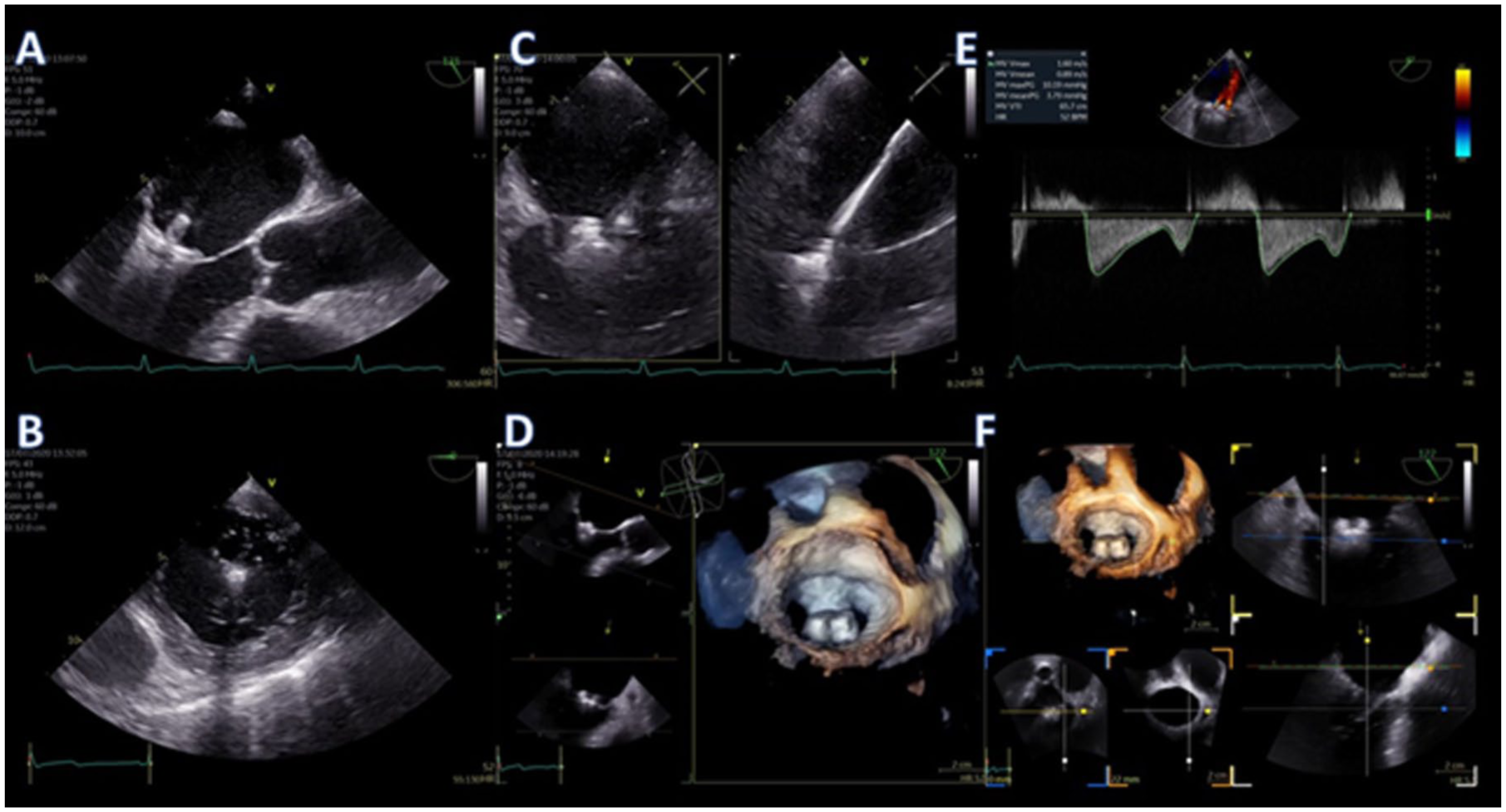
Most patients require a baseline TEE assessment prior to proceeding with LAAO. This focuses on establishing whether there is intra-cardiac thrombus particularly of the LA or LAA (Figures 8 and 9). If thrombus is detected in either of these areas, it is an absolute contraindication to proceeding with LAAO. Furthermore, assessment of the interatrial septum (IAS) for patent foramen ovale (PFO) or ASD and mobility allows planning for transseptal puncture. Baseline assessment of the MV function and left-sided pulmonary veins should also be obtained. 76

A 56-year-old patient with a history of tachycardia-induced cardiomyopathy and non-valvular atrial fibrillation with high stroke risk, who presented for elective left atrial appendage occlusion due to recurrent major gastrointestinal bleeding on oral anticoagulation, representing a contraindication to long-term anticoagulation therapy. Routine TEE demonstrated this large multi-lobulated and mobile thrombus in the LAA (a). 3D imaging confirmed the independent movement and protrusion of the thrombus through the LAA ostium (b) so the procedure was abandoned.
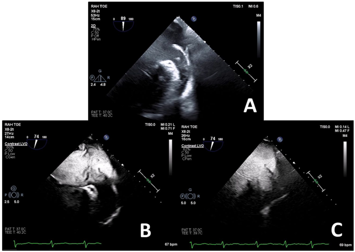
A 65-year-old patient with a history of dilated cardiomyopathy and non-valvular atrial fibrillation at high risk of stroke, who presented for elective left atrial appendage occlusion due to a contraindication to oral anticoagulation, representing an inability to use long-term oral anticoagulant therapy. Routine TEE demonstrated significant spontaneous echocontrast in the LA and LAA with possible thrombus versus artefact in the LAA (a). Perflutren-lipid echo contrast was administered demonstrating slow flow in the LA and LAA but eliminated the echo artefact (b). There was extremely poor flow in the LAA with incomplete opacification only after 30 cardiac cycles (c) so after discussion the procedure was abandoned due to risk of thromboembolism.
Accurate assessment of LAA morphology and sizing of the landing zone is essential for device sizing and predicts the likelihood of successful device deployment. It is commonly performed by imaging the LAA in end-systole at 0°, 45°, 90° and 135° determining the minor and major lengths of the landing zone. Due to the nature of 2D imaging, there is always a degree of uncertainty when it comes to planar imaging when measuring the LAA. This can be overcome by utilising 3D MPR, done live or retrospectively with a stored 3D dataset. In this mode, the two long axes of the LAA (from the orifice to apex) are aligned perpendicular to the short axis of the orifice. This subsequently generates an en-face view of the landing zone allowing precise measurement of its largest diameter. 79 Similar to TAVR annulus sizing, 3D measurements of LAA landing zone correlates with 2D sizes but generally are larger and demonstrate stronger correlation to final device sizing with less post device leakage. 80 Undersizing of LAA closure devices increases the risk of para-device leak, instability and embolisation, whereas oversizing increases the risk of perforation and cardiac tamponade. 81 The LAA wall is comprised of pectinate muscle usually thinnest in the posterior aspect less than 1 mm. 79
Techniques and tools for real-time guidance
TEE-guided transseptal puncture allows precise movement of the delivery catheter into the LA and a more favourable trajectory of equipment into LAA. To achieve this, a more inferior and posterior transseptal puncture is favoured for anteriorly directed delivery to the LAA. This is achieved with biplane TEE guidance at 45° short axis and 90° bicaval views, providing an anterior–posterior and superior–inferior orientation, respectively. In this way, the tenting of the septum and subsequent puncture can be performed in the inferior/posterior segment of the fossa ovalis. The biplane visualisation allows more precise localisation of the puncture, which may need to be varied depending on the orientation of the LAA. In addition, live visualisation enables the operator to avoid a puncture that is too anterior, which could potentially puncture the aortic root or too posteriorly which could cause tamponade by puncturing through Waterson’s groove. Insertion of the sheath and delivery catheter can be performed with 3D/4D imaging to allow better overall visualisation and avoidance of the catheter tip abutting the LA wall or its withdrawal back into the right atrium. The LAAO device is then advanced towards the LAA and confirmed by fluoroscopic contrast injection, TEE and subsequently deployed (Figures 10 and 11).

A 67-year-old patient presented for routine 12-month follow-up of LAAO. The medial rim of the Amulet closure device is in close association with the MV leaflets but with no significant interaction (a). 3D echo showed a slight lift of the medial aspect of the device at the level of the mitral annulus (b).

Utilisation of 3D/4D-TEE to guide pigtail catheter placement into the LAA during percutaneous LAAO.
Adequate deployment of the LAAO ‘Watchman’ device is confirmed by assessing the ‘Pass’ criteria – position, anchor, size and seal. 76 Position of the device is assessed to determine the correct ‘lie’ at the LAA orifice. If not positioned correctly in the long axis of the LAA, the device may exhibit excessive shoulder protrusion, encourage device thrombus formation and inadequate exclusion of the LAA. This can be assessed by 2D biplane or utilising 3D/4D to better visualise the extent of the device in relation to the orifice and MV. The ‘tug test’ is performed to assess anchorage to ensure that the device returns to the original deployed position on TEE and fluoroscopy. Size is assessed by confirming adequate device compression which is defined as between 8% and 20% for the Watchman device – this is measured at 0°, 45°, 90° and 135° ensuring the central catheter attachment is in view. This can also be performed using MPR similar to pre-device assessment.
Assessment of peri-device leaks is performed using 2D colour Doppler. Even small leaks (0–5 mm) after LAAO are common and have been associated with a modestly higher incidence of thromboembolic and bleeding events, particularly when ⩾3 mm. The size of the leak is also an important determinant of its temporal regression: peridevice leaks ≤3 mm tend to regress over time, whereas those >3 mm often remain unchanged. Comprehensive evaluation of a peri-device leak should consider not only its dimensions but also its potential mechanisms. 82
Reduction of the colour scale (Nyquist limit) to 20–30 cm/s is recommended and 3D/4D colour may be used to better visualise the degree of circumferential leak.74–76 In challenging cases, a contrast agent may serve as an alternative to cardiac CT. 83 After satisfactory device deployment, it is important to assess for potential complications such as left pulmonary vein obstruction, development of a pericardial effusion, MV dysfunction and an iatrogenic interatrial septal defect. 81
Atrial septal defect
Patient selection and evaluation
Transcatheter treatment of secundum ASD and PFO is the preferred modality of choice for patients meeting criteria for closure when anatomically suitable. 84 Evaluation for ASD closure is complex and requires an assessment of right heart size, function and shunt fraction, that is whether the lesion causes haemodynamically significant left to right shunting. This can be performed by several modalities including cardiac magnetic resonance imaging, TTE/TEE or invasive cardiac catheterisation. 85 Patients are considered for PFO closure if they have suffered a cryptogenic stroke and are under 65 years of age, and the PFO is assessed as embolism related. 86
Initial suspicion for significant ASD is usually identified by TTE in the presence of right heart dilatation or colour flow across the IAS. 84 The most common form of ASD is the secundum ASD (75%–80%) followed by primum, sinus venosus and coronary sinus defects. 87 Shunt fraction (Qp/Qs) can be assessed using TTE or TEE by comparing stroke volumes of the right and left heart. This is calculated using the following formula:
where: Qp/Qs = CSALVOT × VTILVOT /CSARVOT×VTIRVOT
CSARVOT, cross-sectional area of the right ventricular outflow tract; VTIRVOT, velocity-time integral of the right ventricular outflow tract; CSALVOT , cross-sectional area of the left ventricular outflow tract; VTILVOT, velocity-time integral of the LVOT.
This calculation is more challenging to perform with TTE due to the anterior positioning of the right ventricular outflow tract (RVOT), as its superior border may sometimes fall outside the echocardiographic window. Additionally, measurement errors in outflow tract diameters are squared, further impacting accuracy. 85 Confirmation of ASD anatomy is usually best evaluated by TEE due to the anatomically close relationship of the IAS to the oesophagus with high temporal and spatial resolution. Initial assessment of the defect size can be achieved with 2D multi-planar imaging with or without colour Doppler. However, this may underestimate the true size of the defect as the septum is not flat and the defect is not always circular. 84 3D/4D-TEE with the MPR method can accurately assess the size and the shape of an ASD and has a better correlation with balloon sizing which is often used by interventionists. Suitability for percutaneous closure is determined by the presence of the rims and the size of the defect itself. ASDs larger than 40 mm cannot be treated with an Amplatzer occluder and surgical closure is the only option.
Colour Doppler should be applied sequentially to identify small fenestrations or additional ASDs. 3D/4D colour Doppler can help differentiate dropout artefacts from a true defect and provide a better understanding of the size and location of the ASDs. Current guidelines suggest imaging the IAS at 15° increments from the mid-oesophageal window to evaluate the defect relationship to the aortic and tricuspid valves, caval connections, LA roof and pulmonary veins. At a minimum, there are six anatomical rims, which should be described as deficient (<5 mm distance between the defect and surrounding structure) or absent (<1 mm distance between the defect and surrounding structure). The superior–anterior (aortic) and inferior–posterior rims are measured at 45° in the short axis view of the AV. The inferior–anterior (atrioventricular) and posterior–superior (pulmonary vein) rims are measured at 0° in the four-chamber view. Finally, superior vena caval and inferior vena caval rims are evaluated at 90° in the bicaval view. 88
More complex defects, such as sinus venous ASDs, may benefit from multimodality imaging such as cardiac MRI as the caval structures may lie outside the echocardiographic window and may be associated with anomalous pulmonary venous drainage. 89
PFO is far simpler to assess by echocardiography due to its predictable location and extent of the defect. By definition, a PFO has no absence or deficiency of atrial tissue but rather a transient functionally journal tunnel or flap between the septum primum and secundum. Therefore, there are no tissue rims to be deficient.84,90 Factors that increase the likelihood of PFO implicated stroke include presence of atrial septal aneurysm, hypermobility, large spontaneous shunt on colour Doppler, prominent Eustachian valve or Chiari network. 91 Performing a TEE/TTE-agitated saline bubble study in patients with suspected right to left shunting on TTE or transcranial Doppler can isolate the shunt to the atrial level, visualise bubbles crossing the septum and quantify the degree of the shunt. 84
Risk stratification and procedural strategy
Pre-procedure planning and suitability for transcatheter ASD closure is important in preventing complications. Device undersizing or instability due to deficient rims may result in residual shunt, device embolisation or emergency surgery and oversizing can lead to device erosion. This is potentially a fatal sequelae, and particularly so when there is a deficient aortic rim. 92
3D/4D-TEE provides incremental information regarding complex defect shapes (oval, triangular, egg or pear shaped), fenestrations, multiple defects and a better overall view of the defect in association to its surrounding structures (Figure 12). It provides an en-face view of both the right atrial (RA) and LA aspects of the defect, better understanding of the adequacy of rims for percutaneous closure and visualisation of the dynamic change in defect size/shape during the cardiac cycle. ASD dimensions may be measured using MPR in both the end atrial-systolic and diastolic phases to assess the changes during the cardiac cycle. This facilitates more accurate device selection and sizing. 93 It is particularly important in complex ASDs with a non-circular shape to utilise 3D/4D-TEE to better appreciate the maximal and minimal defect diameters (Figure 13). This is because traditional 2D techniques may over or underestimate the defect size depending on the sector cut-plane. 84
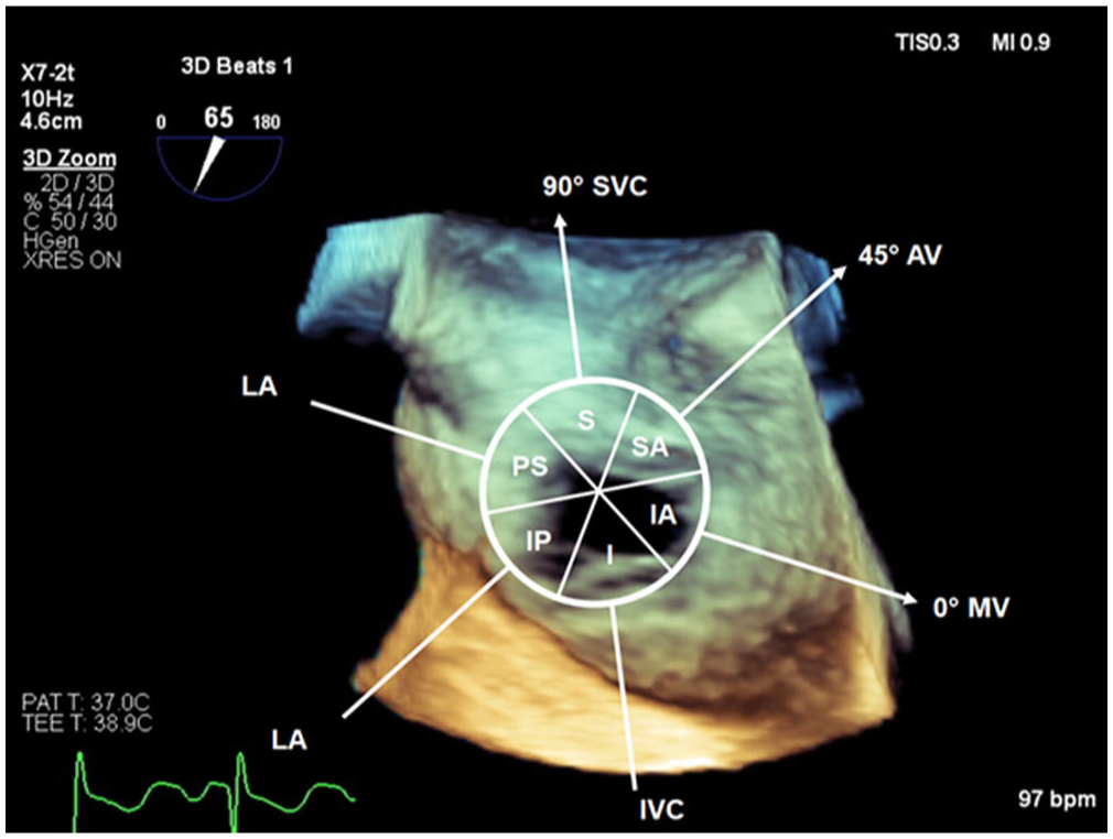
Schematic representation overlaid over 3D volume of IAS and ASD from the RA aspect demonstrating the surrounding structures and rims (SVC, AV, MV, IVC, LA). Sequential 2D assessment of the IAS will assess the respective rims: 0°: posterior–superior (PS) and inferior–anterior (IA), 45°: infero-posterior (IP) and superior–anterior (SA), 90°: superior (S) and inferior (I). The 3D en-face view enables the whole defect to be assessed with respect to the structures and rims.

A 35-year-old patient presented for re-attempted percutaneous ASD closure. Panels a and b demonstrate the defect and rims using 3D/4D echocardiography from the RA aspect in end atrial-diastole and end atrial-systole, respectively. The change in size and geometry with the cardiac cycle demonstrates the ‘dynamic ASD’. 3D MPR was performed to accurately size the closure device in end atrial-diastole (panel c). The patient had a previous unsuccessful closure attempt due to underestimation of the ASD size by 2D echo.
Deficient rims are a common finding in assessing ASD with up to 42% of patients having a deficient superior–anterior rim adjacent to the non-coronary cusp of the AV. However, despite this, only a minority of patients require surgical referral for ASD closure. 88 Adequate tissue rims allow effective anchoring of the ASD occluder, provide defect closure and prevent adverse interactions between the device and adjacent structures. These structures include the atrio-ventricular valves, right sided pulmonary veins, coronary sinus and caval connections. Deficient or absent rims in any location other than the superior anterior (aortic) rim are usually deemed not suitable for percutaneous closure and are referred for surgical management. In cases of deficient or absent superior–anterior rim, the occluder ‘straddles’ the aortic root and the Nitinol mesh prevents damage to the aortic tissue. Oversizing in this situation, however, increases the risk of erosion and complications.84,88,92
Techniques and tools for real-time guidance
Baseline procedural assessment of cardiac function should occur to enable comparison after device deployment to check for any complications or unintended interaction with other cardiac structures. 92 Intra-procedurally, 2D-TEE and 3D/4D-TEE are utilised to visualise the delivery system traversing the defect (Figure 14) and partially deploying in the LA avoiding the pulmonary veins, roof and appendage. The device is then deployed under direct vision ensuring adequate tissue within the closure device. This can be performed by continuous rotation of the multi-planar probe or with bi-plane imaging performing a sweep from left to right across the device. This is repeated with colour Doppler to ensure no significant residual shunt or device leak. Finally, 3D/4D may be used to visualise the device in situ and to observe adequate closure and any residual defects. 84 Post-procedure imaging is performed to make sure that the device does not impinge on vital structures and to ensure the absence of pericardial effusion that may be indicative of a perforation.

A 40-year-old patient presents for percutaneous PFO closure. Live 3D imaging is used to guide the deployment of the left atrial disc (a). The disc is then pulled back towards the interatrial septum to occlude the left atrial side of the PFO tunnel (b).
Conclusion
Echocardiography is essential in structural heart interventions, guiding pre-procedural planning, real-time execution and post-intervention assessment. Advances in 3D/4D imaging and Doppler techniques have enhanced precision, safety and procedural success while refining diagnostic accuracy and therapeutic decision-making.
As transcatheter interventions continue to expand, echocardiographic imaging will remain central to ensuring procedural success and patient safety. Future advancements in imaging modalities will likely continue to enhance the role of echocardiography, making interventions even more precise and tailored to individual patient needs. By integrating cutting-edge imaging technologies with a multidisciplinary heart team approach, the field of SHD interventions is poised to continue innovating and improving clinical outcomes.
Footnotes
Acknowledgements
The authors would like to sincerely thank all patients who participated in the studies reviewed, the echocardiography technicians for their invaluable assistance in image acquisition and all members of the catheterisation laboratory team for their support and contributions to clinical practice and research.