
Abstract
In this research, a bio lubricant was developed utilising eco-friendly constituents of jatropha oil, polytetrafluoroethylene (PTFE) and sodium dodecyl benzenesulphonate (SDBS), characterised and tested with four-ball tribometer under ASTM D2783 standard. The tribological performance in terms of friction, wear, load carrying ability and evaluation of the film behaviour on stability and strength was conducted. According to Fourier transform infrared spectroscopy (FT-IR) of the study, the presence of the two additives in base jatropha oil demonstrated good functional groups desired for lubricant lubricity. In comparison to base jatropha under 40 kg and 1200 rpm, blended 1 wt-% PTFE + 0.8 wt-% SDBS additives produced an outstanding reduction in coefficient of friction (61.4%) and good load carrying strength among all the samples tested, but commercial shell oil (CSO) outperformed under wear resisting potential. Scanning electron microscopy (SEM) and a 3D surface profilometer were used to examine the rubbed surfaces. Findings indicate that the boundary film on the worn surface was made up of PTFE and SDBS nanoparticles that deposited film elements of sulphur and higher carbon content. The decrease in the percentage of iron (Fe) indicates that tribo-pairs were separated from direct contact under additives usage. According to the research, adding an anti-wear substance to the new formulation could increase wear protection, thus effectively making it comparable with CSO counterpart.
Introduction
In lubricant formulations and lubrication applications, viscosity modifiers are essential constituents that are frequently taken into consideration. Due to system operating conditions and internally generated friction, lubricants required a suitable additive that would maintain the base lubricant's viscosity during service.1–3 The most common answer for such a task is polymers for viscosity improver operations. Many polymers have been subjected under tribological testing to discover the extent to which they perform as lubricants by reducing wear and friction. Polytetrafluoroethylene (PTFE) has been utilised extensively in the field of tribology due to its unique physical and chemical properties, 4 such as exceptional chemical stability, 5 corrosion resistance, high lubricating viscosity,6,7 and low friction coefficient. 8 Okechukwu et al. 9 examined the behaviour of PTFE suspensions in rolling/sliding contacts and found that PTFE particles can be used to reduce friction and wear when suspended at low concentrations in oils. Since PTFE's low wear resistance limits its application, much effort has been made using PTFE in different vegetable oils to improve its tribological property. It has been demonstrated that adding micro/nano-sized particles to PTFE additives improves their tribological performance.9,10 The expectations must be accomplished with an optimal compatibility between the vegetable oil and the supplementary polymer.
In contemporary engine oil, additives with carbonyl, alkene and aliphatic CH2 and CH3 group groups have been employed extensively. Long-chained alkyl derivatives of oil-soluble ester triglycerides that are carbonyl functional are frequently utilised as detergents, dispersants and viscosity modifiers. Alkylbenzene sulphonate materials with top-notch tribological performance have recently been created, 11 owing to the fast and effective tribo-film formation. The compatibility between the base oil and added additive affects the creation and growth of the film during the lubricating process. Additionally, the system's capacity to produce frictional energy during operations aids in the effectiveness of the film and degree of friction and wear reduction. Therefore, in this present research, friction, and wear reduction of base jatropha oil together with PTFE and sodium dodecyl benzenesulphonate (SDBS) will be investigated. The compatibility, tribo-reactions, film behaviour and strength during sliding operations were also examined. The jatropha oil used in this study was chosen for its eco-friendliness and desired inherent functional groups that support lubricant lubricity.
Materials and method
PTFE (40–75 nm) and SDBS (13–24 nm) powders were purchased from Sigma Aldrich firm Malaysia together with base jatropha vegetable oil (BJO) and commercial shell engine oil (CSO). According to the manufacturer, 12 the base jatropha oil used in this work is a crushed seed form. Despite having several uses, the synthetic fluoropolymer of tetrafluoroethylene known as polytetrafluoroethylene (polytetrafluoroethylene or polytetrafluoroethylene) excels as a lubricant polymer. PTFE could be distinguished from other materials owing to its smooth surface, high melting point, and resistance to many chemicals. The molecular structure SDBS and PTFE are presented in Figure 1.
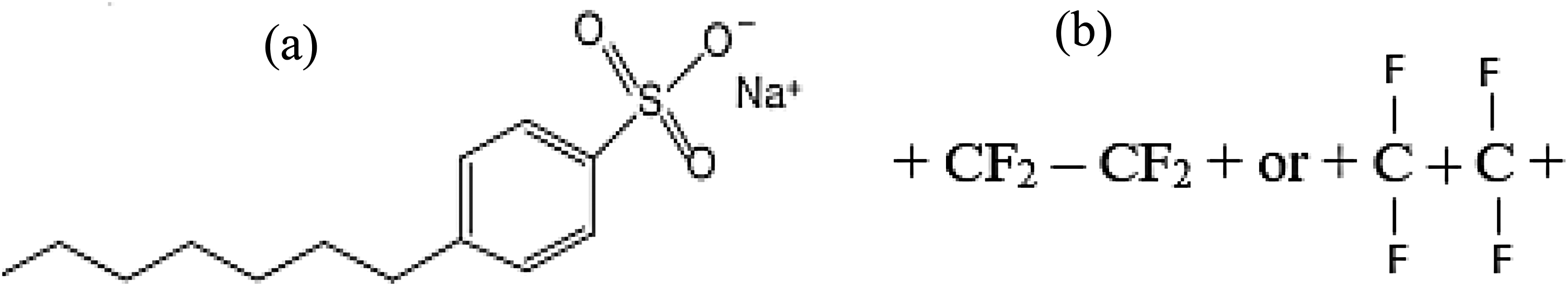
Molecular structure of SDBS (a) and PTFE additive (b).
The standard oil (jatropha oil) was used to determine the polymer performance and compatibility when used in lubrications with different concentrations (PTFE) and SDBS. Figure 2 displays the lubricant-PTFE nanoparticle mixing/formulations and the behaviour of PTFE under temperature variations. The hydrophobicity of the uncharged polymer backbone determines how much the PTFE compresses when it is in an uncharged condition. 13 Based on the state of the monomers, these charge adjustments and interactions with SDBS and PTFE occur. The formulation (base jatropha + PTFE + SDBS) was thoroughly mixed using a high-powered sonication machine for 2 h:30 min to prevent the agglomeration of nanoparticles and improve stability. The selection of the 0.5 wt-%, 1 wt-% and 1.5 wt% concentrations PTFE and 0.4 wt-%, 0.8 wt-% and 1.2 wt-% SDBS were chosen based on previous literature recommendations.14,15
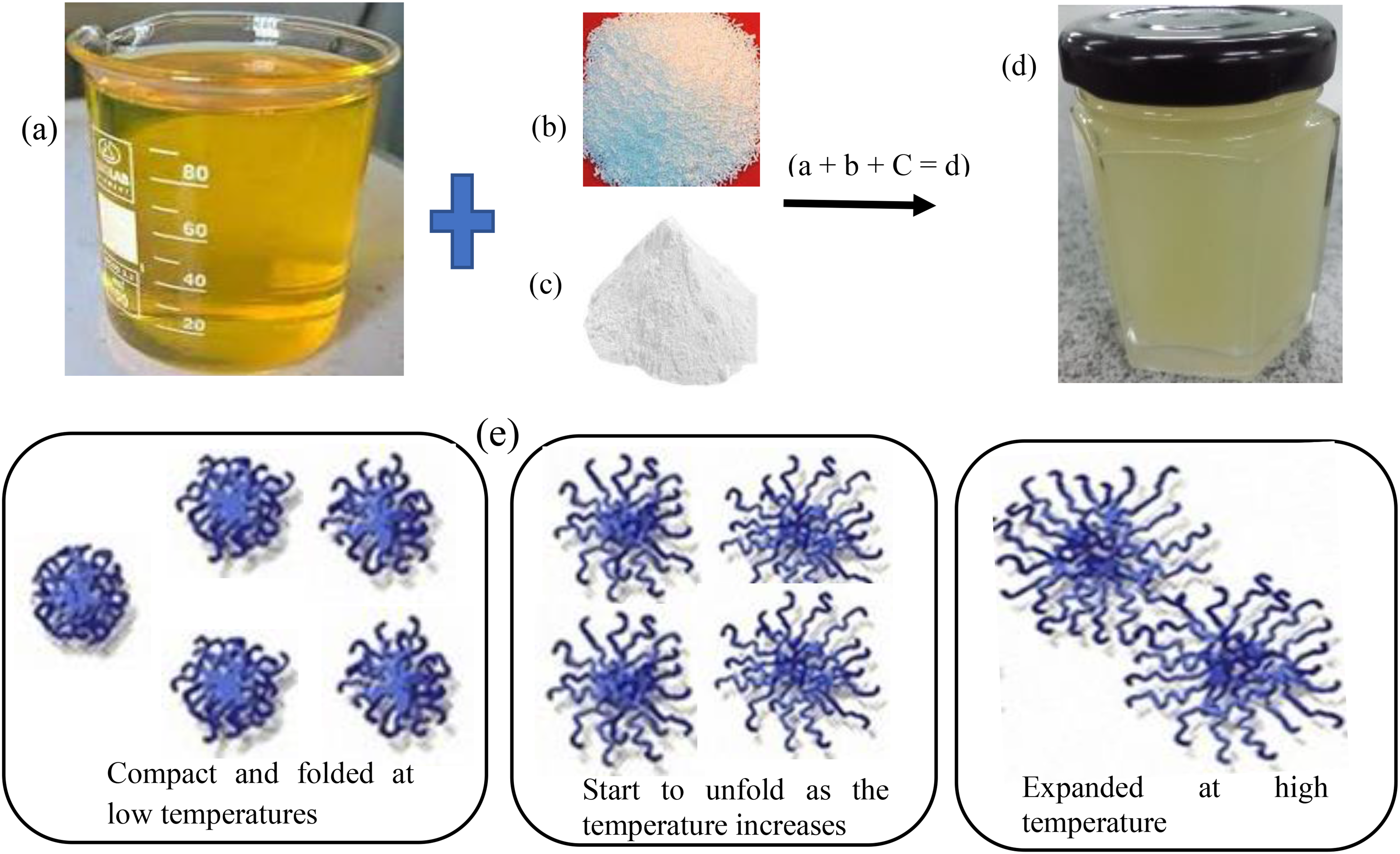
Lubricant formulation: base jatropha oil (a); PTFE (b); SDBS (c); PTFE + SDBS blended with jatropha oil (d) and the behaviour of PTFE polymer under temperature variations (e).
To conduct investigation of the nature of the materials used and tribological properties, many instruments were utilised on additives, lubricants, and contact surfaces of the specimens. The viscosity of the lubricants was measured using HK-265A apparatus with capillary tube tested at 40 °C and 100 °C, according to ASTM D 445 standards. To determine the morphology of the nanoparticles, a scanning electron microscope (SEM) (JEOL JSM-6010PLUS/LV) was used. The composition of the elements components on the rubbing surfaces was examined using the energy dispersion of X-rays (EDX). According to ASTM D3828 standard, flash point of the lubricants was determined using SETA flash point machine, conducted as presented by Golshokouh et al. 16 Before any testing, 100 scans (background and sample) must be finished, according to Alizadeh et al. 17 With spacers of 13 mm in diameter and 0.025 mm thick, the test material with a 5 mm thickness was employed.
To examine the wear surfaces diameter of the lubricated specimens, an optical microscope (OM) was used. The arithmetic means of the surface roughness (Ra) and surface depth (Rz) of the lubricated specimens was measured using OM 3D surface profilometer. To understand the ppm worn on the balls after lubricants lubrication, spectrochemical analysis using rotatory disc spectrometer (Spectroil 100 series) was conducted in accordance with ASTM-D6595 standard, thus ultrasound re-agitation of the samples for 30 min was performed prior to the test. A volume of 50 mL of each lubricant (unused and used) was made available to the laboratory in their customised analysis bottle.
Experiment procedure
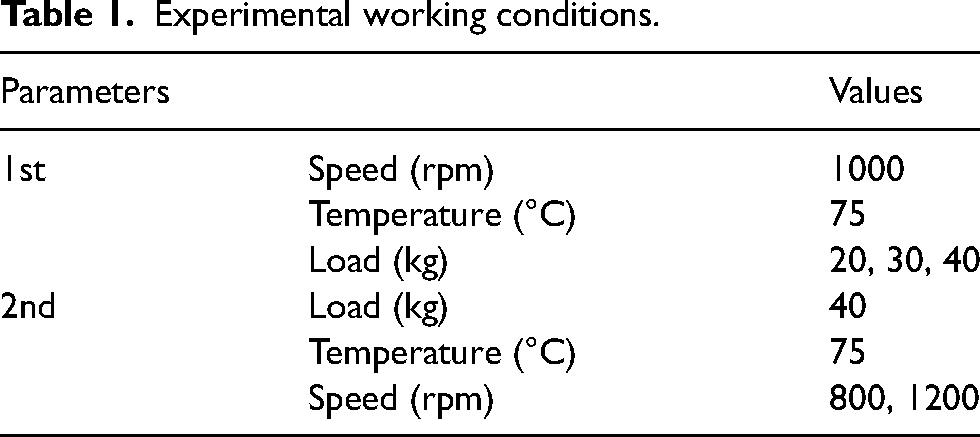
The four-ball friction tribo-tester was used to investigate materials’ capacity for wear resistance and friction reduction in accordance with ASTM D-4172 standard as seen in Figure 3. The selection of the working parameters was based on the ASTM standard to compare the tribological performance of the formulation at different loads and speeds. As affirmed from literature,18,19 that adequate frictional energy along with good tribo-reaction are operational working depended. The internal structure of the four-ball tribo-tester machine consisted of an upper moving specimen in contact with a lower specimen that was set in a temperature-controlled oil bath. In this study, the effects of applied load and sliding speed on the tribological properties of PTFE together SDBS were comprehensively studied. Before adding the various surfactant concentrations, the polymer concentrations were examined for the best performance during the lubricant experiment to determine their synergistic or antagonistic tendency. The detailed test parameters are illustrated in Table 1. The friction coefficient was recorded by a force transducer during the entire sliding test. For a total of 30 min and 1 h, depending on the analysis stage, each lubricant was tested at a temperature of 75 °C. In practical applications, load and speed are important parameters directly influencing the hydrodynamic pressure of the oil film, 20 thus could be used in determining the resistance strength of lubricating oil additives in separating body on sliding surfaces.
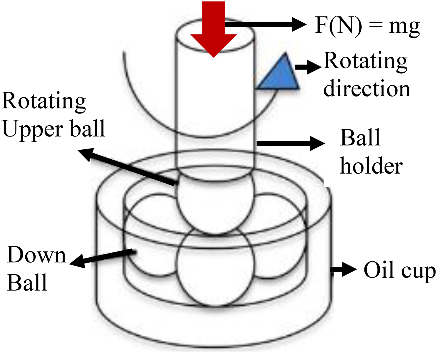
Four-ball tribometer balls arrangement/mechanism.
Experimental working conditions.
In the analysis, the upper and lower specimens were made of alloy steel (12 mm) with Hardness value 59–61 HRC and density (ρ) (g/cm3) of 7.79. The surface roughness (Ra) and surface depth (Rq) of ball sample's original surface was ranging between 0.02 and 0.09 µm for Ra, while Rq ranging between 0.03 and 0.08 µm. They were made of GCr15 bearing steel (AISI-52100) with a composition of C, 0.95–1.05 wt%; Si, 0.15–0.35 wt%; Mn, 0.20–0.40 wt%; P, <0.027 wt%; S, <0.020 wt%; Cr, 1.30–1.65 wt%; Ni, <0.30 wt%; Cu, <0.25 wt%. After each test, tissue paper and degreasing cotton were used to gently wipe away excess oil from the surfaces of the composite sample and counterpart. Additionally, the sample and counterpart were washed in an acetone bath to get rid of any remaining oil.
Wear is the term for the weight loss that occurs as a result of relative motion and friction of the contacting surface. The lower the value of COF and wears on the lubricated surface, the better the lubricant property, thus the lubricant would have a good film strength. Several factors, like the surface's nature (dry or wet),
21
orientation with relation to the counter face's sliding direction, affect durability of a surface.22,23,24 Equation (1) allows for the following deduction regarding the lubricant film strength as used by Paleu et al.
25

Characterisation of samples used
Figure 4 displays high resolution (100×) SEM representations of the morphology of PTFE and SDBS using a JEOL JSM-6010PLUS/LV. The image demonstrates that the aggregated particles were uniformly dispersed with the formation of pores, showing the capacity to dissolve in lubricant, in contrast to the SDBS sample, which had a clearer appearance. The results agree with reported findings.10,26 The manufacturer report in the additive's manual via supplier (Sigma Aldrich firm Malaysia) states that PTFE has a nanosize of 54 nm, which is within the nanorange, whereas the nanosize of SDBS was 14 nm. The EDX analysis is shown in Table 2, revealing the presence of carbon, sodium and sulphur in SDBS while PTFE demonstrated the presence of carbon and Fluorine elements, meanwhile zirconium (Zr) element was from the coating process. The data from the earlier study was like the elements mentioned.27–29
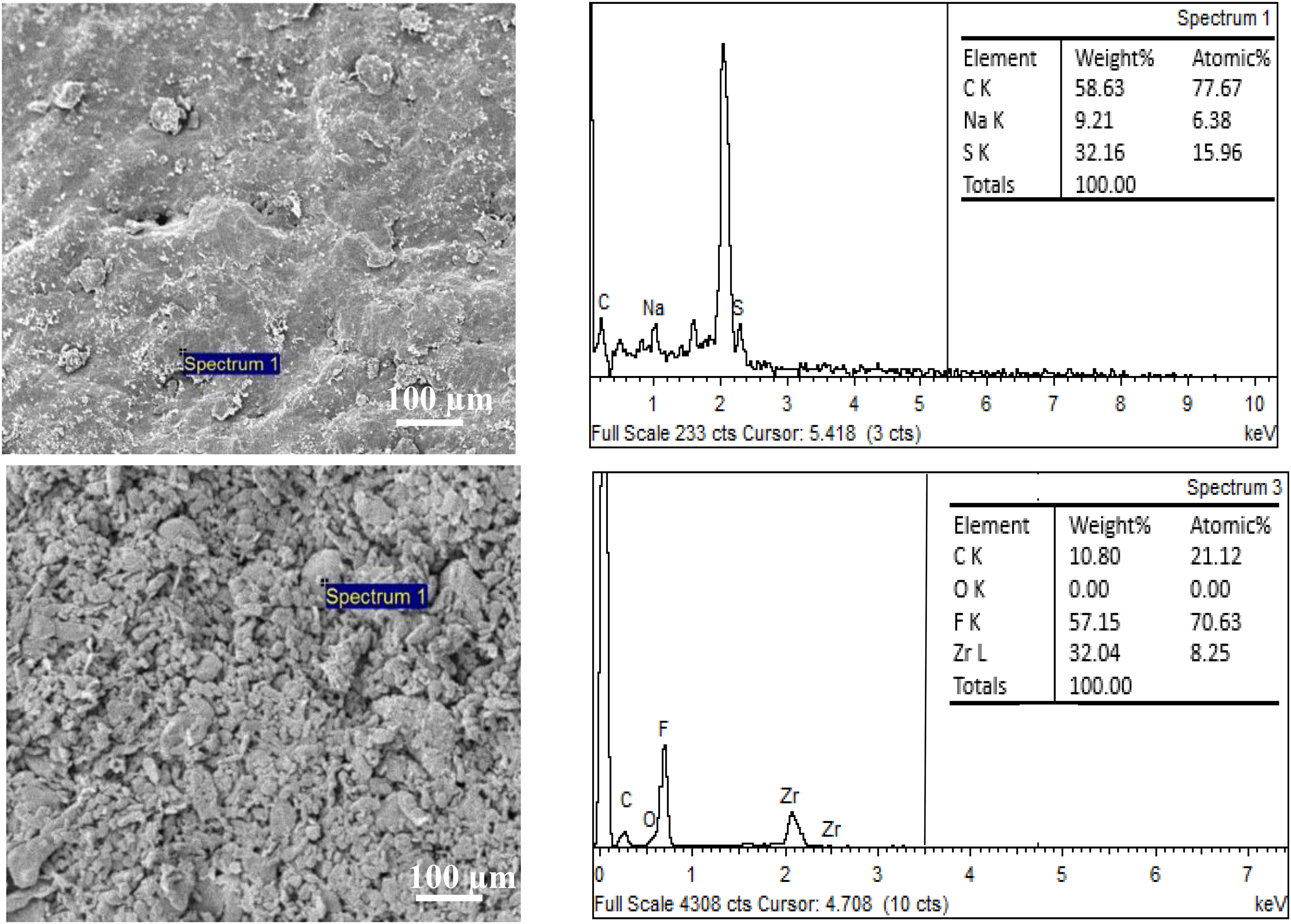
SEM micrographs and corresponding EDX of SDBS and PTFE particles.
The samples kinematic viscosities (cSt), densities and viscosity index at different temperatures.
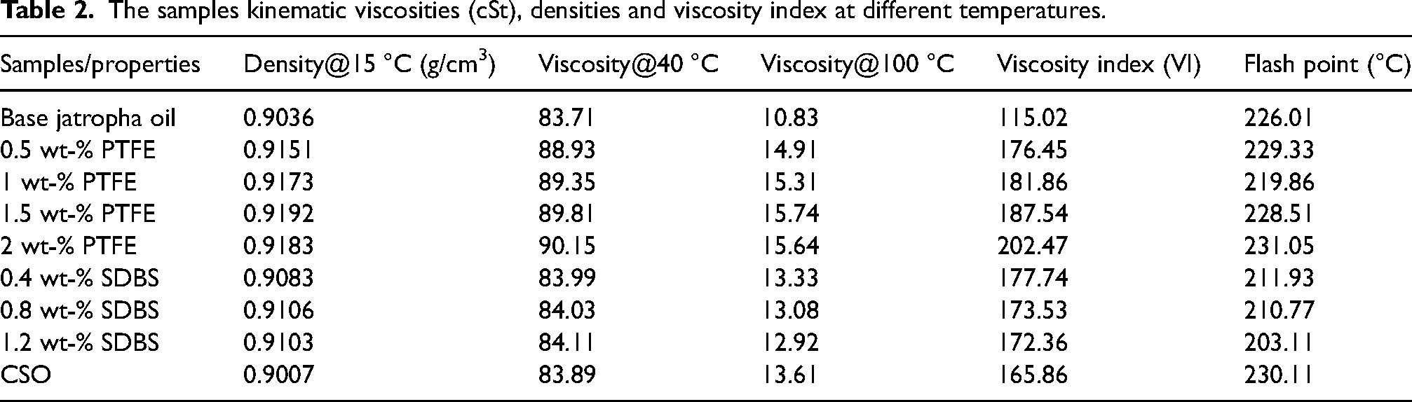
An important factor in the examination of lubricating fluid is the viscosity index (VI), thus obtained from the lubricant viscosity values at 40 °C and 100 °C. The introduction of polymeric additives causes a rise in the viscosity index (VI), observed in Table 2. This might be as a result of the polymer constituent dissolving in base lubricant, which causes long molecular chains to coil into polymer coils in the oil. 18 Prior to being added to a set 150 mL volume of base jatropha oil, the chosen PTFE concentration was mixed with various concentrations of SDBS separately because surfactants were combined to improve the stability of the lubricants. To create a homogenous solution, the mixture was next passed through a sonicator 740 ultrasound machine for 30 min. The polymer chains become more relaxed and tend to extend expands as a result of the interaction between the polymer chain and the oil molecules that occur as the temperature rises (the swelling process). The base stock's viscosity decreases as a result of the increase in temperature, 14 thus reduces under inclusion of PTFE. The application of SDBS reduces the viscosity of base lubricant due to its tendency of reducing lubricant molecular interactions. The results show that PTFE has a greater viscosity index than SDBS lubricants. This indicates how the polymer additive was successful in raising the viscosity index of the base stock. This is comparable to a literature reports.18,30
Using FT-IR analysis, Figure 5 illustrates the functional groups present in the base lubricant blended with SDBS and PTFE polymer. Apart from the early drop curve of PTFE in base oil, every other section of the curve appears similar to the blended additives owing to functional groups. The spectra of the samples show aliphatic stretching bands CH3 and CH2 at 2931 cm−1 and 2822 cm−1 and functional group deformation bands for methyl and methylene CH3 and CH2 at 1608 cm−1 and 1437 cm−1. When comparing the behaviours and functional groups in the spectra of the different samples, a more noticeable band at about 3481 cm−1 was found in the PTFE but reduced under SDBS blended samples spectra owing to the lesser amount of O–H/N–H group. Investigations discovered that the hydroxyl group (OH) is associated with a rocking vibration in the PTFE spectra at the 3118 cm−1 band, which was insufficient for SDBS samples and caused peak shift. This is because at ambient temperature and without external influence, the propagation of oil monomers components inside the polymer chains had a little difference in the structure.14,31
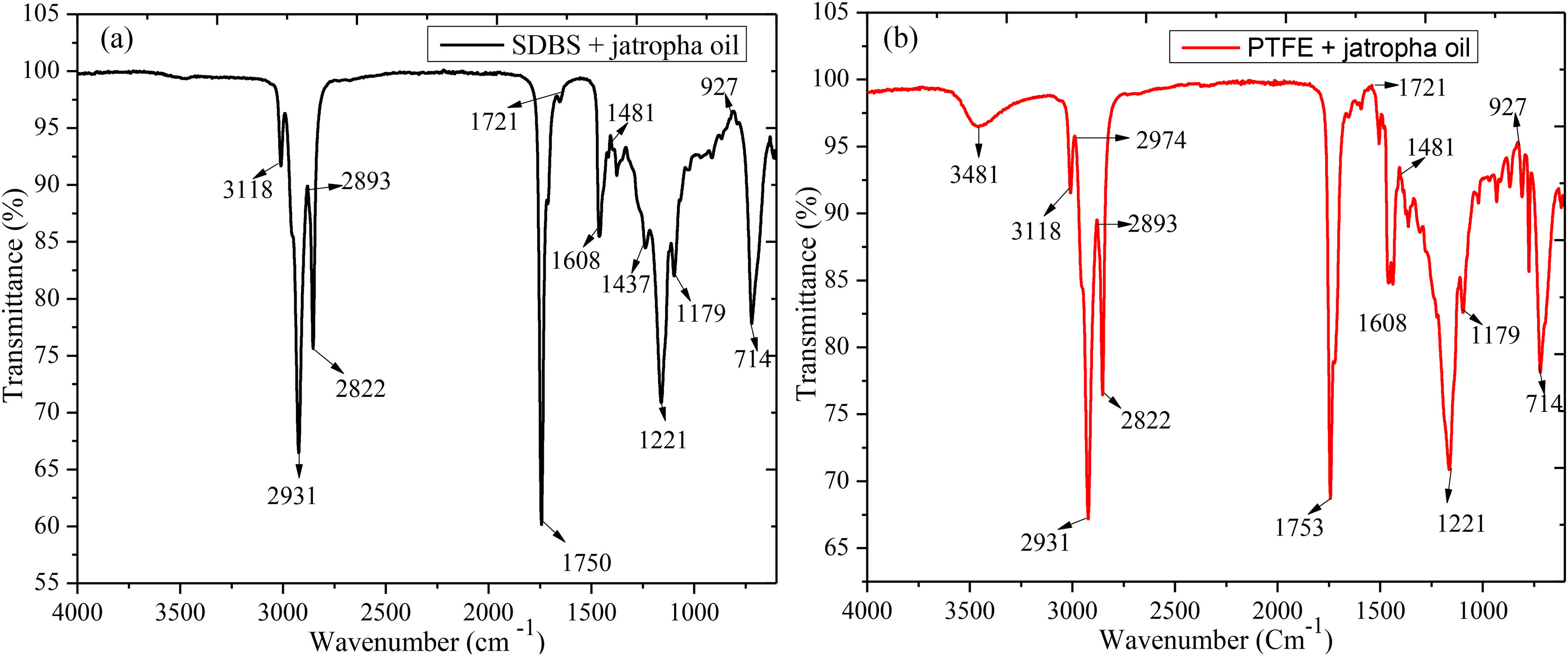
The FT-IR presentation of the SDBS (a) and PTFE (b) additives in base jatropha oil.
All samples showed a stretching vibration of the carbonyl group C=O but PTFE sample clearly displayed the curve at 1753cm−1. Peaks at 1481 cm−1 and 927 cm−1 were developed because of the N–H group's high vibration and its shared vibration with the C–H group. The observations on the various additives functional groups demonstrated similar in base jatropha revealing good compatibility when blended, thus expected good lubricity when use in lubrications. The discovered functional groups were in agreement with previous report. 14
Figure 6 depicts the effects of various PTFE and SDBS concentrations in base jatropha oil. Figure 6(a) shows the average COF for three distinct loads 20 kg, 30 kg and 40 kg at a rotational speed of 1200 rpm and a temperature of 75 °C over an interval of 30 min. Ideally, in tribological investigation, load, speed, and temperature affect the way lubricants work during operations. As can be observed, base jatropha had the highest COF, with an increase in COF as load increased from 20 kg (0.2517) to 30 kg (2554) to 40 kg (0.2559). Under PTFE additives, 0.5 wt-%, 1.5 wt-%, and CSO showed similar behavioural patterns, displaying almost the same value of COF as load increased from 20 kg to 40 kg, whereas 1 wt-% and 2 wt-% PTFE provided similar trend with little decrease on COF as load increased from 20 kg to 40 kg under 1200 rpm compared to the base jatropha lubricant. The displayed results were similar with reported polymeric composite lubricant performance. 32 The use of SDBS demonstrates poor results owing to its lubricating function and molecular structures. Table 3 displays the COF reduction caused by the application of PTFE, SDBS and CSO. The analysis revealed that the film that formed between the sliding bodies caused the decrease in COF values and similar COF values as the load increased. This reduced direct contact, thereby reducing friction. According to the findings, PTFE performed better than CSO at 0.5 wt-%, 1 wt-% and 1.5 wt-% in lowering COF, thus supported previous report on PTFE COF reduction. 33
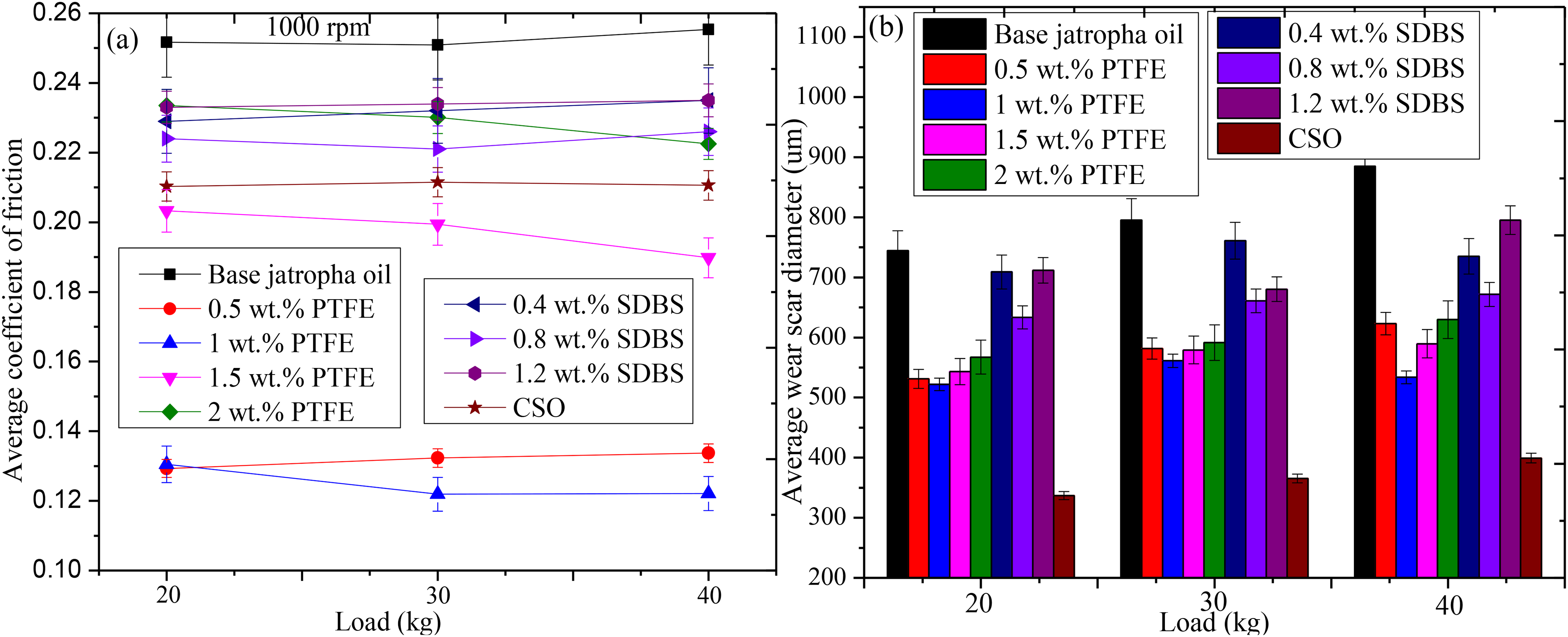
COF (a) and WSD (b) for the different PTFE concentrations in base jatropha lubricant (100 rpm, 75 °C, 30 min duration).
Percentage (%) reductions from various PTFE and SDBS additives against base jatropha oil.
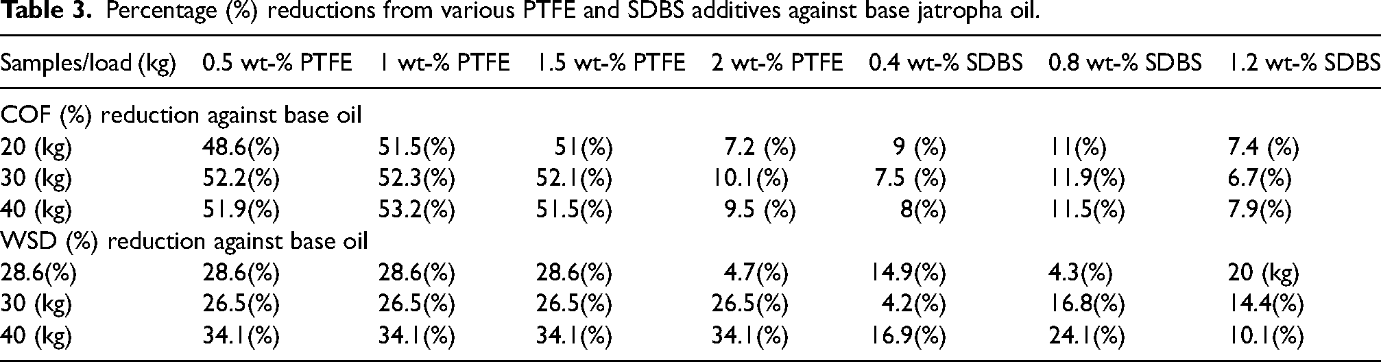
Figure 6(b) shows the variation in the average wear scar diameter of the lubricant samples. As demonstrated, the wear scar diameter closely correlates with the concentrations under different loads, showing a notable reduction in the wear scar diameter of the steel balls compared to the base jatropha. It was clearly shown that base lubricant lacked protection on the sliding contact, resulting in excessive WSD with values of 744.3 µn under 20 kg, 795.1 at 30 kg and 885.13 for 40 kg, respectively using 1200 rpm. The wear scar diameter was lowest for all tested conditions when 1 wt-% PTFE concentration was used apart from CSO sample. Again, the application of various SDBS yielded poor results, this is because of lack of anti-wear compositions. 15 The various percentage reductions on the WSD from the lubricants are presented in Table 3. Despite having high COF results (Figure 6(a)), CSO produced the best WSD decrease in all conditions tested. This was made feasible by the formulation's inclusion of an anti-wear constituent. The reduction in wear scar diameter may be attributed to the transfer film that was created by the self-smooth molecular friction of the PTFE particles, however, the performance was unsatisfactory when compared to CSO. It was suggested that adding anti-wear or a surfactant to the formulation of PTFE lubricant might improve its anti-wear characteristics.
Again, the best PTFE concentration (1 wt-%) underwent further enhancement analysis using SDBS surfactant. Surfactant was added as a means of enhancing the tribological performance of PTFE-blended jatropha oil by establishing good solution stability while decreasing agglomeration during lubrication. This enhancement efficacy was reported by Gulzar et al., 34 and Opia et al. 35 According to recent findings, excellent lubricant lubricity is complemented by good lubricant stability. Figure 7 displays the COF for the optimal PTFE concentration with the addition of various SDBS concentrations using 40 kg at operating speed of 800 rpm and 1200 rpm under 75 °C, along with the corresponding percentage reduction in wear scar diameter (WSD) and wear depth (WD). The COF of base lubricant alone was 0.1608, whereas 1 wt-% PTFE yielded 0.1205 as presented in Figure 7(a). With the addition of 0.4 wt-% SDBS, 0.8 wt-%, and 1.2 wt-%, respectively, generated 0.1054, 0.109 and 0.1315. The performance were similar with findings on the previous tribological analysis conducted. 36 All additives used reduced friction, however using SDBS performed poorly but better than base jatropha oil. This resulted in average percentage COF reductions of 56.5%, 61.4% and 21%, respectively, when utilising 1 wt-% PTFE, 1 wt-% PTFE + 0.4 wt-% SDBS, 1 wt-% PTFE + 0.8 wt-% SDBS and 1 wt-% PTFE + 1.2 wt-% SDBS samples, compared to the base oil. Oil samples with 1% PTFE + 0.8% SDBS modifications in base oil demonstrated greater levels of friction reduction in friction tests than 1 wt-% PTFE nanoparticles. As stated in literature, 18 that frictional energy with good tribo-reactions contribute in steady film formation during lubrication as to reduce COF. The study observed a sharp rise in the COF with the use of 1 wt-% PTFE + 0.8 wt-% SDBS, thus suggested to come from breaking of film as a result of inadequate frictional energy and later formed. It was also discovered under base jatropha oil.
Variations of the COF against operating time under different rotating speeds; 800 rpm (a); 1200 rpm (b) and wear scar diameter reduction (%) (c); wear depth reduction (d) on the various samples against base jatropha lubricant.
Figure 7(c) and (d) revealed the outcomes of the wear tests conducted using base jatropha oil, 1 wt-% PTFE together the inclusion of 0.4 wt-% SDBS,0.8 wt-% SDBS and 1.2 wt-% SDBS additives. Apart from 1 wt-% PTFE + 1.2 wt-% SDBS, which produced comparable values with base jatropha oil, the wear scar diameters and depths for other lubricated surface were decreased as compared to the wear scar depths with base oil. The WSD and WD generated by the base lubricant were 795.3 µm and 10.51 µm for 800 rpm and 888.3 µm and 10.17 µm for 1200 rpm, respectively. It was discovered that WSD and WD reduction increased under 1200 rpm as a result of the increased level of frictional energy required for an effective tribo-reaction and good tribo-film formation. The reduction obtained upon mixing PTFE and SDBS showed that the two additives produced synergistic effect. This is similar with literature reports.37,38 Furthermore, the nanofluid's improved solubility contributed to effective wear reduction since the nanoparticles penetrated the contact area rapidly and formed a strong tribo-film. Due to the absence of anti-wear elements, the wear protecting performance of new formulations could not be compared to that of commercial shell lubricant, suggesting that the addition of such a supplement would further improve tribological performance.
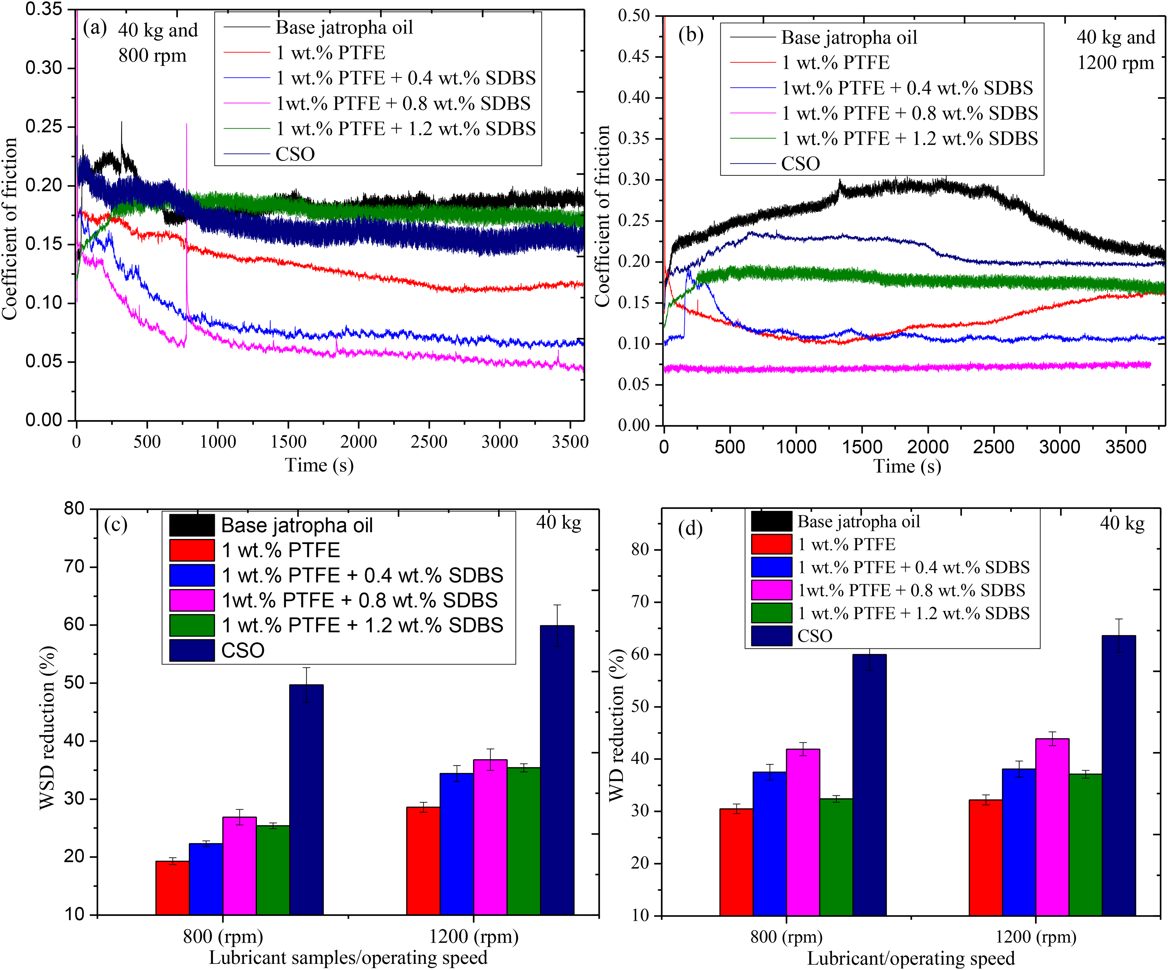
As shown in Figure 8, a tribological evaluation of the lubricants was conducted to explore the lubricant film stability and film strength under a load of 40 kg and sliding speeds of 800 rpm and 1200 rpm for 1 h. Apart from 1 wt-% PTFE + 0.8 wt-% SDBS, which showed abrupt deformation of the film between time of 750 s (s) and 820 s of operation time, the graphs showed film unsteadiness under 800 rpm in the beginning of each lubricant sample before turning steady as shown in Figure 8(a). Under 1 wt-% PTFE exhibits unstable between 0 s and 260 s, while base jatropha lubricant demonstrated unstable film was observed between 0 s to 630 s. Under the action of 0.4 wt-% SDBS, the film was unsteady from 0 s to 250 s, whereas 1.2 wt-% SDBS generated the reverse pattern of a steady film curve gradually moved upward. The breakdown of the lubricant film's molecular structure was due to an internal effect suspected to be caused by insufficient frictional energy for stable film formation.19,39 Besides, machine vibration was another reason for the film's unsteadiness and deformation. Similar unstable film was observed between 0 s and 260 s using CSO. The observations reported were similar with previous findings. 40
Film stability graph (a) and lubricant film strength (b); (40 kg, 800 rpm, 1200 rpm, 75 °C).
Under 1200 rpm, generated films had a more pronounced increase from the beginning of the operation. Similar behaviour curves were seen when base jatropha and CSO were used, with the film becoming unsteady between 0 s and 80 s and 0 s and 30 s, respectively. Film was reported to be unstable between 0 s and 30 s when only 1 wt-% PTFE was used. With application of 0.4 wt-% SDBS, displayed irregular film between 80 s and 550 s, whereas 1.2 wt-% SDBS exhibited consistent film throughout the operation with an increase in COF at the start. The best film stable behaviour produced an exceptional COF decrease when 1 wt-% PTFE + 0.8 wt-% SDBS was used. Under 1200 rpm operations, the trend path of the COF exhibits an upward and downward pattern during this film breaking. This reflects comparable behaviour to the previous report on the film analysis of 1.0 mass% MoS2 and 0.7 mass% SiO2. 41 The findings demonstrate that, in comparison to 1 wt-% PTFE, lubricant containing 0.8 wt-% SDBS exhibits good lubricity by retaining the intended lubricant film during sliding.
The film strength of the different lubricants was estimated using Equation (1). As can be seen in Figure 8(b), higher operating conditions (1200 rpm) produced stronger films than lower operating configurations (800 rpm). This can be attributed to the outstanding film formation with reduced friction and wear due to good frictional energy generation and tribo-reactions.25,42 Under the application of base jatropha oil, 1 wt-% PTFE, 1 wt-%PTFE + 0.4 wt-% SDBS, 1 wt-%PTFE + 0.8 wt-% SDBS, 1 wt-%PTFE + 1.2 wt-% SDBS and CSO, yielded film strength of 0.00032 Pa, 0.00049 Pa, 0.00042 Pa, 0.00060 Pa, 0.00057 Pa and 0.0013 Pa, respectively for 800 rpm whereas 1200 rpm produced 0.00026 Pa, 0.0015 Pa, 0.0018 Pa, 0.0020 Pa, 0.0019 Pa, 0.0050 Pa, respectively as revealed.
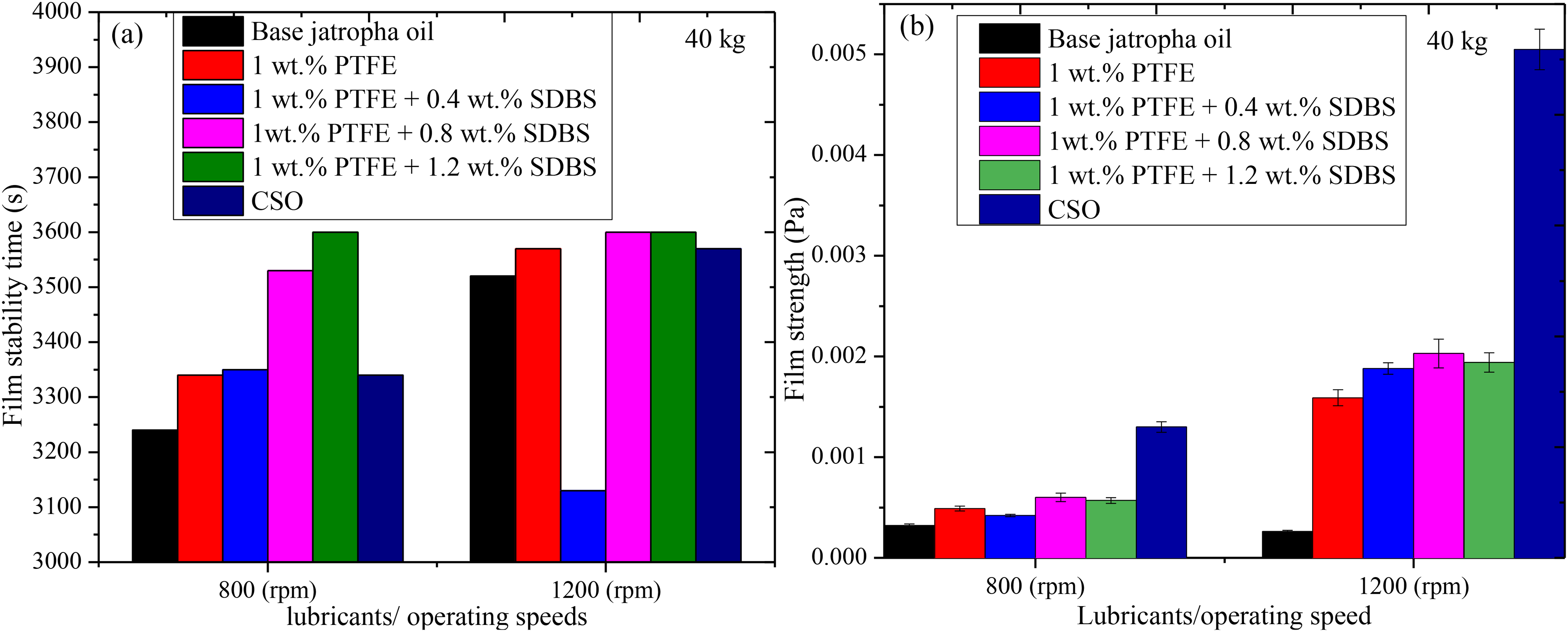
As demonstrated in Figure 9, the use of OM analyses on the tribo-pair worn surfaces was carried out in order to explore the nanolubricants (PTFE and SDBS) strength in protecting the elements surfaces. It was discovered that the wear scar diameter under the jatropha base was wider, uneven, rougher and deep grooves than the samples containing additives. It was revealed that the inclusion of SDBS makes the formulation more homogeneous and stable, thereby enhancing penetration of nanoparticles into the contact zone leading to wear reduction. This findings were similar to the previous reports.4,33 Additionally, numerous visible large and deep grooves were found parallel to the direction of sliding. According to Figure 9(a)–(f), the analysis produced WSD of 888.3 µm, 634.3 µm, 582.4 µm, 561.3 µm, 573.5 µm and 355.8 µm, respectively. Although the additives reduced wear but performed poorly in comparison to CSO in terms of wear protection, suggesting that additional improvement could be achieved by adding an anti-wear constituent.
Optical microscope images of the various lubricants lubricated surfaces: base jatropha oil (a); 1 wt-% PTFE (b), 1 wt-% PTFE + 0.4 wt-% SDBS (c), 1 wt-% PTFE + 0.8 wt-% SDBS (d), 1 wt-% PTFE + 1.2 wt-% SDBS (e), and CSO (f): (40 kg, 75 °C), 1200 rpm and 1 h operations).
Furthermore, it is possible that certain tiny particles embedded on the worn surface are causing surface mending based on the variation in the WSD and the corresponding micrographs as stated in similar analysis.43,44 It can be regarded as a PTFE and SDBS nanoparticle deposit. The AFM surface roughness and SEM/EDX examination can provide evidence that the nano-additive is effective in reducing wear as presented in Figures 10 and 11. The tribo-interface wear is influenced by the lubricant compositions, interaction of surface and particle additives. Figure 10(a)–(f) shows the change in Ra and Rz after testing with various lubricants. The average Ra and Rz were calculated using three lines drawn across the worn lubricated surface. The Ra and Rz decrease when PTFE and SDBS are applied, which is consistent with earlier studies, owing to the SDBS acting in cleaning the contact surfaces. This was supported by the early report on surfactant operations in lubrication.45,46 Under the use of base jatropha, 1 wt-% PTFE, 1 wt-% PTFE + 0.4 wt-% SDBS, 1 wt-% PTFE + 0.8 wt-% SDBS, 1 wt-% PTFE + 1.2 wt-% SDBS, and CSO produced Ra and Rz values of 2.83 μm and 11.75 μm; 2.05 μm and 10.35 μm; 1.93 μm and 10.13 μm; 1.15 μm and 9.75 μm; 1.75 μm and 10.11 μm; 1.09 μm and 7.03 μm, respectively.
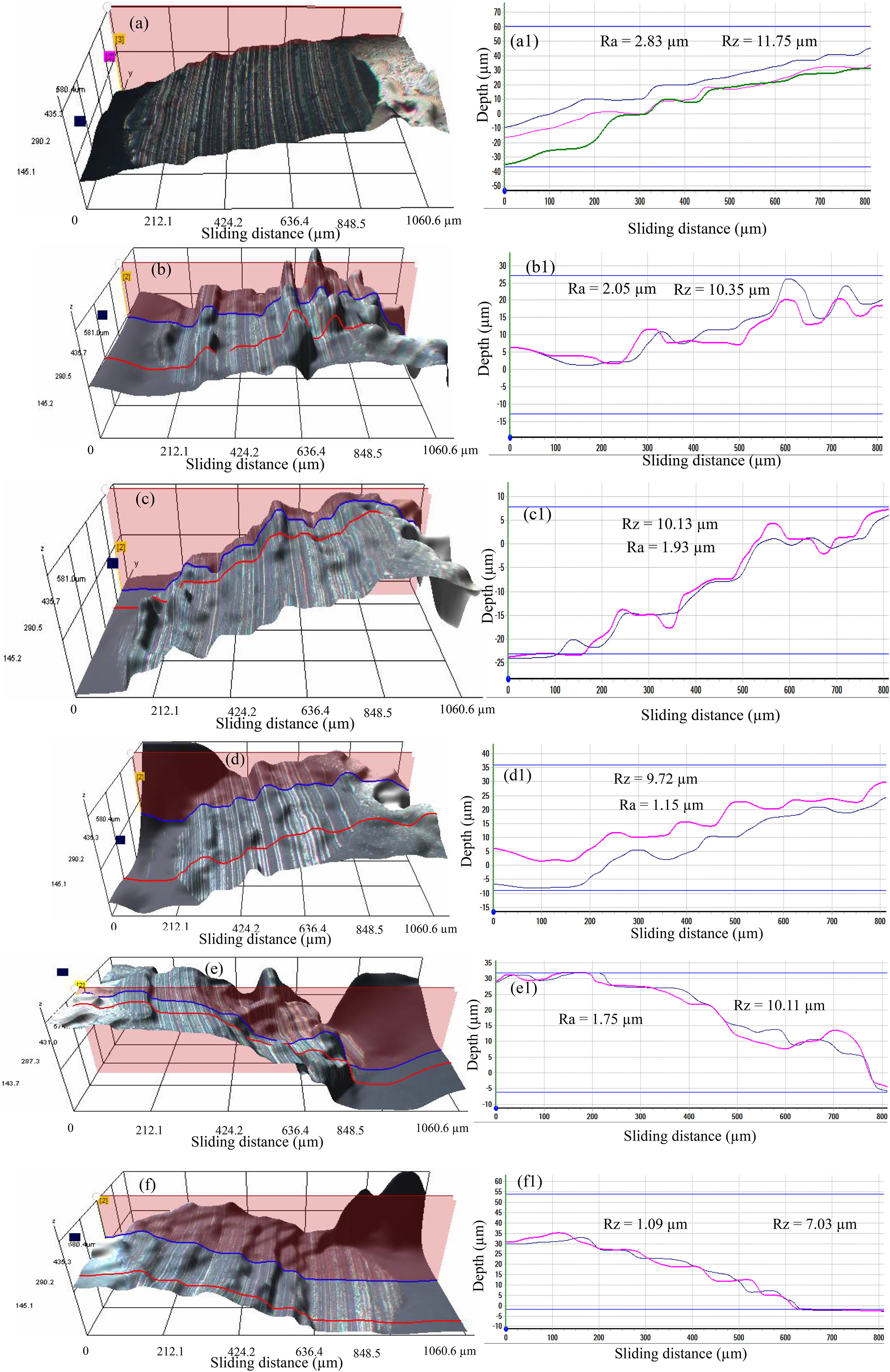
3D images (a–f) and micrographs (a1–f1) of the lubricated surfaces: base jatropha oil (a–a1); 1 wt-% PTFE blended (b–b1); 1 wt-% PTFE + 0.4 wt-% SDBS (c–c1); 1 wt-% PTFE + 0.8 wt-% SDBS (d–d1); 1 wt-% PTFE + 1.2 wt-% SDBS (e–e1); commercial shell oil (f–f1) (load 40 kg, 75 °C, 1 h duration).
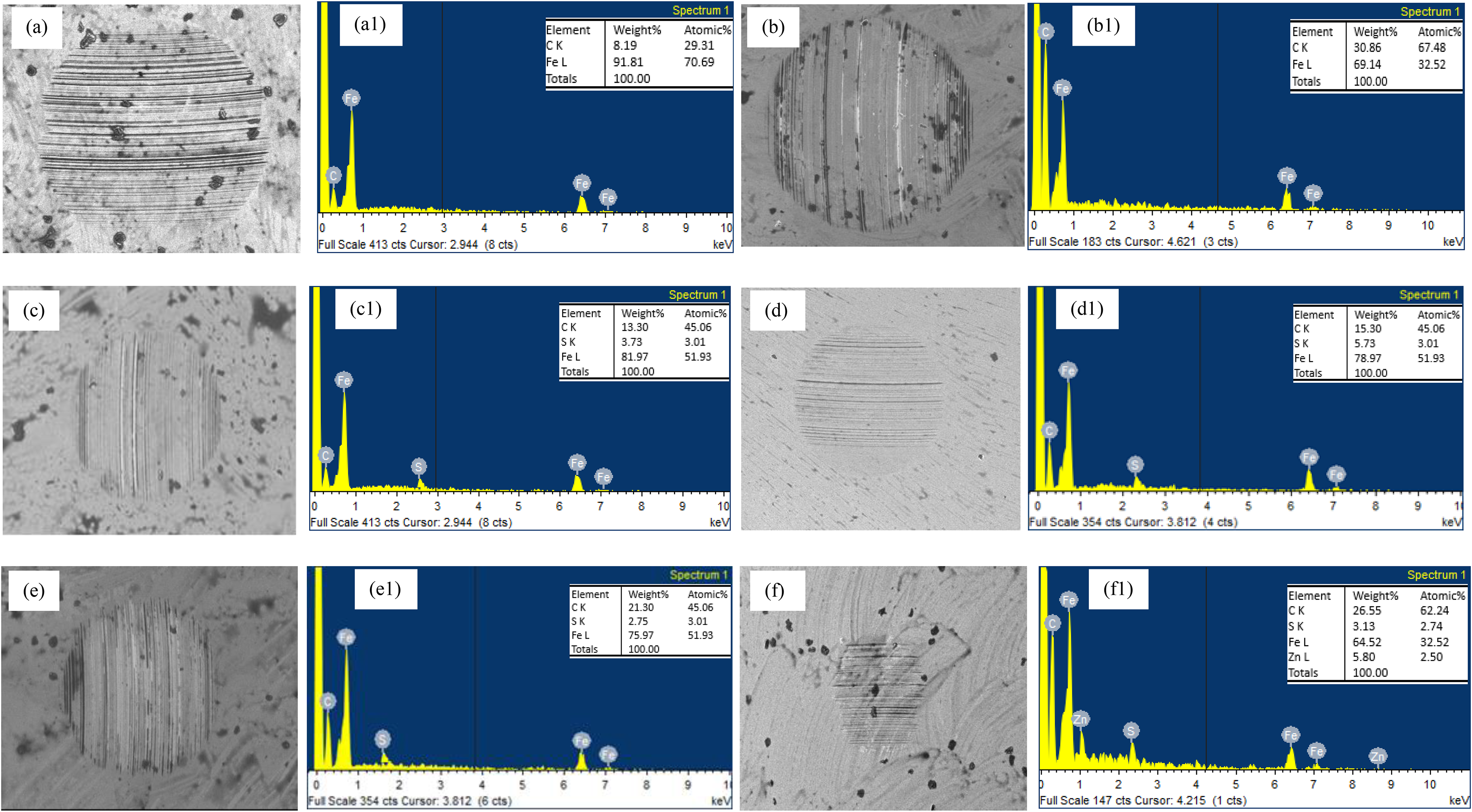
SEM images and EDX of the balls lubricated with different lubricants: base jatropha oil (a–a1); 1 wt-% PTFE blended (b); 1 wt-% PTFE + 0.4 wt-% SDBS (c); 1 wt-% PTFE + 0.8 wt-% SDBS (d); 1 wt-% PTFE + 1.2 wt-% SDBS (e); commercial shell oil (f) (load 40 kg, 75 °C, 1 h duration).
A further experimental demonstration of the tribo-film on sliding contact interfaces is provided in Figure 11 by the element's distribution on the wear scar as indicated by EDX. According to white spots on the SEM map and shown in Figure 11 (a), Fe and C were discovered on the rubbing surface under the base jatropha lubricant application. Only Fe and C were found, indicating that the tribo-pairs were in direct contact. With the application of PTFE, a high percentage of C and a decrease in Fe generated (Figure 11(b)). Order lubricants also revealed the presence of sulphur (S), which is from the SDBS nano-additive used as shown in Figure 11(c)–(e) but in different proportions. This was in addition to the presence of iron (Fe) and carbon (C). The F additive component PTFE's, however, was not found possible washed-out during cleaning. The nano particles (SDBS and PTFE) contribute to the process that reduces wear by diffusing nano additives into the sliding contact and restricting direct contact between the tribo-pairs elements. This is consistent with earlier findings made during polymer lubrication analyses.47,48 Using a commercial shell lubricant, several elements were found (see Figure 11(f)). According to the investigation, adding an anti-wear component to new lubricant formulae will increase their potential to resist wear, making formulations comparable to CSO in terms of wear protection.
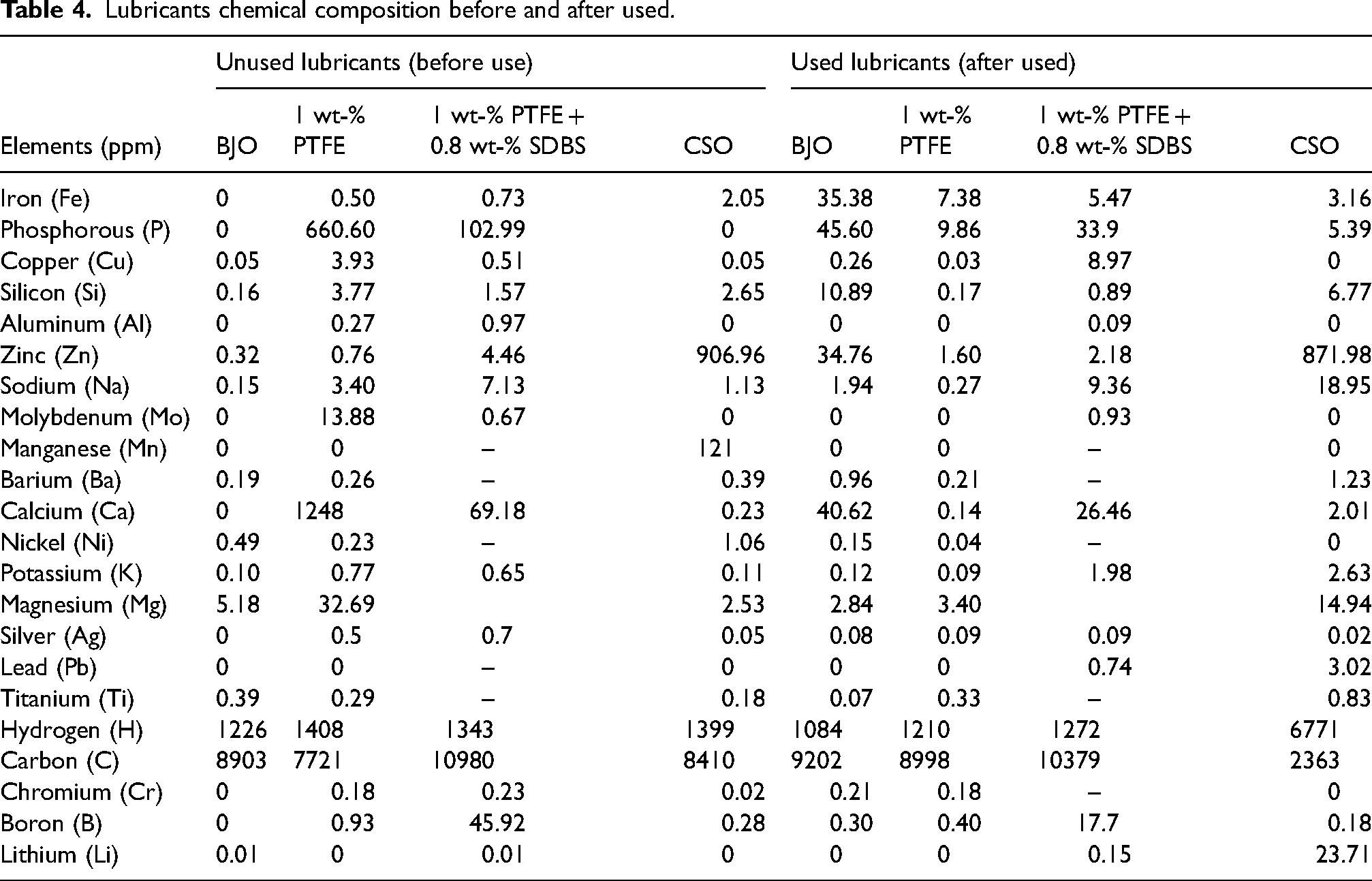
The metallic components of the lubricant were displayed in Table 4 both before and after the operations. In doing this, the particles per million (ppm) of elements in the lubricant ought to be measured. It acts as a gauge to assess the level of ball wear after lubrication operations. The idea behind this study could be used for lubricant diagnostic services Abere et al.'s, 49 analyses claim that a high concentration of steel ball components found after service indicated reduction in the lubricant's ability to protect machine elements against wear. When the lubricants were tested, a variety of elements, including pure metals, alkaline earth metals and metalloids, were discovered. Most of these elements were found in steel alloys, while several were also present in lubricants.
Lubricants chemical composition before and after used.
Lubricants chemical composition before and after used.
It was found that some samples had larger elements ppm in the fresh solution and lowered after been used. This is because the elements were used in the tribo-reaction lubricating process according to Asrul et al. 50 Nevertheless, more elements thought to have been introduced as additives during formulations as in case of CSO with higher ppm concentrations. The main element in the steel ball, Fe, was found to be reduced under PTFE + SDBS compared to the BJO, though the CSO produced the lowest value of Fe after the operations, according to the results of the lubricant analysis. However, some components were seen to be present in greater amounts under PTFE, confirming their inclusion in the formulation and supporting effectiveness in reducing COF, as reported by Xie et al. 38
The intent of this research was to investigate PTFE nanoparticles in base jatropha oil, modified by SDBS on their tribological performance in terms of wear and friction. The findings of this study underline the significance of choosing the best concentration to improve lubricity and reduce wear in the tribo-interface. The outcome revealed that sustainable bio lubricant can be created by choosing a particulate additive that is environmentally friendly, such as PTFE and SDBS, and choosing a bio-base oil like jatropha oil. The results of the present investigation are summarised as followed:
PTFE + SDBS nanoparticles as an oil additive have good COF performance in all the tested conditions better than reference CSO but lack sufficient wear protections like CSO counterpart. The boundary film on the worn surface was composed of BDBS and PTFE nanoparticles depositing film which contributed to improving the tribological properties of the base oil. Under spectrochemical inspection of the lubricants before and after operations, different pure metals, alkaline earth metals, and metalloids were discovered. The increase in Fe when only base lubricant was used revealed poor element body protection while the decrease on the Fe during additive applications served as evidence of wear resistance during lubrications.
Footnotes
Acknowledgments
The authors acknowledge the efforts of the research members of the Green Tribology and Engine Performance Research Group (G-TriboE), Universiti Teknikal Malaysia Melaka, the Department of Mechanical Engineering.
Declaration of conflicting interests
The authors declared no potential conflicts of interest with respect to the research, authorship, and/or publication of this article.
Funding
The authors received no financial support for the research, authorship, and/or publication of this article.