
Abstract
In terms of the research on electric power steering system, there are some problems, such as model uncertain and external interference. However, it is difficult for a general controller to deal with those problems as well as the performance of the system. Therefore, the paper is to propose a control method based on generalized internal model control, which is based on feedback and Youla parameterization, including performance controller and compensation controller. The performance controller is used to make the electric power steering system work well, while the compensation controller is used to solve model uncertain and external interference. First of all, the paper is to establish the model of electric power steering system, introduce the 2DOF vehicle and the tire model, set up the state space of the electric steering system including model uncertain and interference and design the generalized internal model controller. Finally, the simulation and the hardware-in-the-loop experiment are carried out to verify the controller. The results show that the proposed controller takes advantages of better control performance, solving model uncertain and external interference, and improving the performance and robustness of the system.
Keywords
Introduction
The electric power steering system (EPS) is playing an increasingly important part with the development of the smart driving and unmanned driving of cars. 1 EPS is characterized in energy saving, light weight and being easy to control. In the process of the operation of EPS, there are some main problems, including model uncertain and external interference. To end those problems, scholars have conducted a lot of researches. So, various control theories have been used in the electric power steering system.
Classical control theory was applied to the electric power steering system. Yin Chunfang et al. 2 proposed the flexible PID control method with good real-time tracking ability. The PID parameters can be adjusted in real time according to the operating environment, which can make the response capability of the EPS system faster and more accurate. However, due to the difficulty in parameter adjustment and the failure to solve the poor robustness, Zang and Liu 3 found a neural network PID control method that was applied to the EPS system, in which the vehicle speed and torque sensor values as the input of the fuzzy neural network control, and output will be given into the PID. This method is conducive to improve the steering stability and sensitivity.
The control theory methods mentioned above are good ways to improve the EPS performance, but failed to solve its robustness. Therefore, Frédéric Wilhelm et al. 4 proposed two feedback loops with the inner loop being used to estimate the friction, and the other to minimize tracking error. Leea et al. 5 came up with a steering assist and torque tracking control method, and designed a steering torque diagram for reference. Based on the error of the rack force, the sliding mode adaptive method is used for the uncertainty, which improves torque tracking performance of the system to a great extent. However, people pay less attention to the comprehensive control of EPS. Kim et al. 6 presented an EPS-based automatic vehicle system that tried to solve unknown parameters and external interferences. Hu et al. 7 proposed a logical method controlled by power, damping, return and inertia and achieved compensation through the control logic that included the vehicle speed and corner signals to optimize the steering feeling. Xu et al. 8 focused on the current tracking of EPS motors, proposed a H∞ control strategy with mixed sensitivity based on the road interference and noise of the sensor, and carried out simulation and bench experiments, which showed that it was able to achieve fast response of the EPS as well as remove noise from both road and sensor. Both Lee et al. 9 and Faria et al. 10 have got some good results by designing the controllers to solve interference and uncertainty, but on the other hand, they drew little attention to the EPS performance. Zhao et al. 11 designed the controller that integrated H∞ and H2 to make drivers get good road feeling and the system better in robustness. The H∞ method was used to minimize the interference, while the H2 method to optimize the system and implemented the simulation experiment and they got a good end but they paid less attention to the model uncertain. Guojin et al. 12 designed the neuron PID controller as the inner loop and a new robust controller as the outer loop. It could get good responsiveness and robustness. But it lacked experiments to verify real control effect. Dannöhl et al. 13 and Li et al. 14 all paid attention to the road sense of EPS and mainly studied the influence of rack force on the power steering system, estimated the rack force and designed the controller based on the modeling of rack force analysis. It could effectively solve the steering system sense. However, there were still some deficiencies in other performance studies.
The research on EPS mentioned above has made some progress. However, the performance of the controller will be affected due to less researches on the model uncertain and the external anti-interference in the process of its design. At the same time, the researches were ended with simulation experiment, so they failed to verify the real effect of the algorithm because there are differences between the control design model and the actual steering one. Owing to the problems mentioned above, this paper not only pays more attention to the performance of EPS and its model uncertain but also proposes a generalized internal model control method (GIMC) 15 considering feedback and Youla parameterization, including performance controller that is aimed at guaranteeing EPS performance and compensating controller to solve model uncertain and interference. And what’s more, the method will be verified by the EPS hardware in the loop experiment.
The structure is set as follows. The EPS model considering interference is established; The next section designs the generalized internal model controller; then the MPC control and the simulation results of the GIMC are compared; the penultimate section applies two control strategies on the EPS hardware in the loop test bench. Finally, the paper is concluded with conclusions
Model of automobile electric power steering system
Automobile model with two degrees of freedom
The paper mainly focuses on the steering performance of the car, so a simplified car model with two degrees of freedom of lateral and yaw is adopted which is shown in Figure 1.
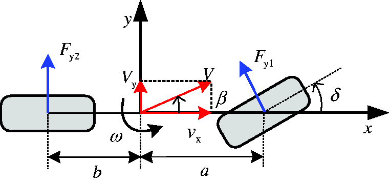
Two degree of freedom vehicle model.
And its differential equation of motion refers to


Among them,
EPS steering system model
In the course of establishing the nominal model of EPS, the author considers its column connection as a rigid one, regardless of the energy loss during the steering. For the research, some degree of simplification was carried out and therefore the EPS structure model can be seen in Figure 2.

Diagram of EPS system dynamics.
In the figure, Ts refers to the measured torque of the torque sensor, Tm is the electromagnetic torque of the motor, Tr is the torque from the steering resistance on the road to the gear, the transmission ratio refers to N, N1Tm is the motor output torque, where N1 refers to transmission ratio of the steering shaft and the motor, θm is the rotation angle, δ1 is rotation angle of the steering shaft, Jp is the equivalent moment of inertia and Bp is the equivalent damping coefficient.
Steering axis model
The dynamical differential equation of the steering shaft of the following part of the torque sensor is

Motor model
The EPS system is studied by a brushless DC motor, and thus the following formulas are derived according to Hall voltage law


Among them, ua refers to voltage, Ka means coefficient of torque, Kb is the coefficient of the back electromotive force, La means the inductance coefficient, Ia means the motor current,
Tire model
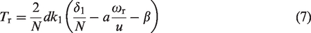
In the paper, the small corner steering is included. Therefore, the tire deformation is characterized by the approximate linear, and therefore the steering resistance torque on the gear through the tire
10
refers to
Establishment of the space state
We can get the following formula based on equations (1) to (7)

Take the state variable
The coefficient matrices A and B respectively refer to
Take the output variable of the system


The transfer function matrix of the state space of EPS refers to

Design of the generalized internal model controller
Youla parameterization
The generalized internal model controller (GIMC) is carried out based on standard feedback control which is shown in Figure 3, where G refers to the actual vehicle model and K to the feedback controller. Generally speaking, it is hard to get the real and accurate EPS model, and therefore we will make use of the simplified nominal EPS model G0.

Block diagram of the standard feedback control.
After the coprime decomposition of the nominal EPS model G0,
16
the result is

Assuming that K0 is a controller that is used to stabilize G0, after the coprime decomposition of K0, the result is

Then all controllers that are used to stabilize G016 can be shown as


Structure of the Youla parameterized feedback control.
Generalized internal model control
By changing input signal position of the structure shown in Figure 4, a new control method, generalized internal model control, came into being. The new control structure in Figure 5 failed to improve the internal stability of the system, because the transfer function from output y to the control signal ui did not change. The transfer function of the two structures from y to ui is derived as follows


GIMC control block diagram.
After derivation, the formula mentioned above can be described as
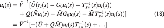

So we can see from formulas (16) and (17) that the transfer functions of the two structures from the output signal y to the control signal ui remain unchanged, and the internal stability is not changed.
The structure of the GIMC differs from that of the Youla parameterized standard feedback in the change of the GIMC in signal
Performance controller on the basis of the EPS nominal model
Performance controller design is a must to ensure the performance of EPS. PID control makes its response and stability better, which is widely used. Therefore, this paper selects PID control as the controller to achieve it. PID controllers fail to deal with model uncertain and interference and noise, but they can be used as performance controllers in GIMC controllers because of its better performance. The control structure of the controller is shown in Figure 6.
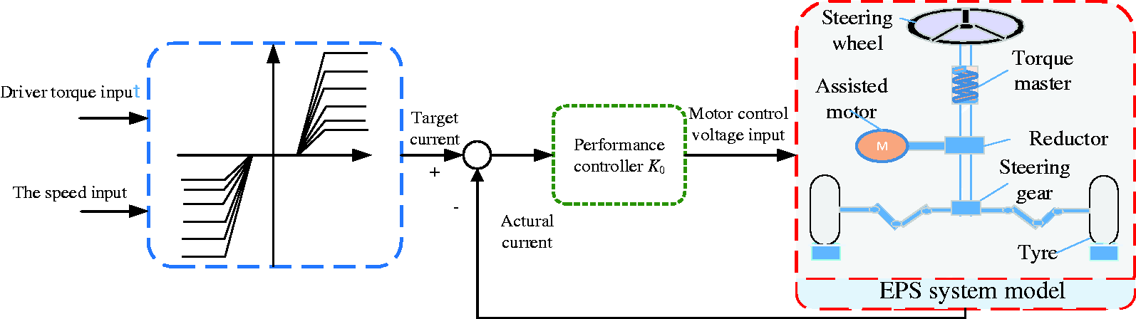
Control block diagram of the PID-based GIMC performance controller.
Compensation controller Q(s)
Since the PID failed to deal with the model uncertain and external interference, a compensation controller is designed in this paper to ensure the robust stability which is shown in Figure 7.

Structure of the GIMC controller with model uncertain.
In general, the model uncertain can be described by linear fractional transformation. 17 As shown in Figure 7, Δ refers to the model uncertain.
For improving the robustness of the system, it is necessary to design a compensation controller Q(s) to obtain the
Among them, Tzw refers to the transfer function from variable z to variable w.
From the structure diagram, we can get

If ri = 0

In the two formulas mentioned above,

For improving the robustness of system, it needs to obtain
From the Figure 7 mentioned above, we can get

If


Among them,
To obtain the controller Q(s) in GIMC, the structure in Figure 7 is transformed into a standard H∞ control structure with model uncertain,
17
as shown in Figure 8, and its generalized controlled object P can be described as

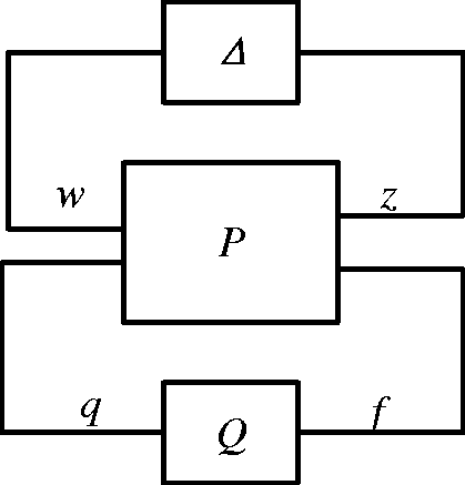
Standard H∞ control structure for linear fractional transformation.
Therefore, the controller Q(s) can be obtained by
Among them

If
Analysis of simulation
The control performance of the proposed GIMC controller and the ability of solving the problem of model uncertain and external interference should be checked, so this paper builds an EPS simulation block diagram based on the EPS system model and the GIMC controller, and simulation experiments are carried out.
Current tracking
One of the important ways to measure the performance of EPS is that the actual current can excellently follow the target current. The controllers’ current tracking capability is verified with a step signal input. Figure 9 shows the response curves of the current tracking under the control of GIMC and that of MPC, respectively.

Response curves of the current tracking.
From Figure 9, we can see that the target current value caused by the step signal input fluctuates about 0.5 s due to the influence of system stiffness and model uncertain, and the actual tracking current under the control of the MPC can work well in the current value, but actually, cannot resist the influence of interference and noise which results in high-frequency oscillating in the current. On the other hand, MPC control fails to solve the model uncertain. Therefore, it will track the target current blind which makes a poor actual control effect. The GIMC control in this paper generates a slight oscillation at the beginning of 0.3 s due to the impact of the step signal. After a while, the tracking becomes more stable owing to the comprehension of the feedforward performance controller and the feedback compensation controller. Compared to MPC control, GIMC control can resist the effects of interference and noise, and at the same time, it can effectively cope with the current fluctuation caused by the model uncertain, ending with a better control effect.
Feeling
It is an important indicator for the driver to measure the feeling of the EPS system by the torque sensor measurement of EPS. The road surface interference and noise of the sensor should be solved for a good EPS system. Therefore, the feeling of the EPS system under the controller as well as the ability to filter interference and noise will be tested by inputting step signal with a noise, the step response input in the simulation should be 5
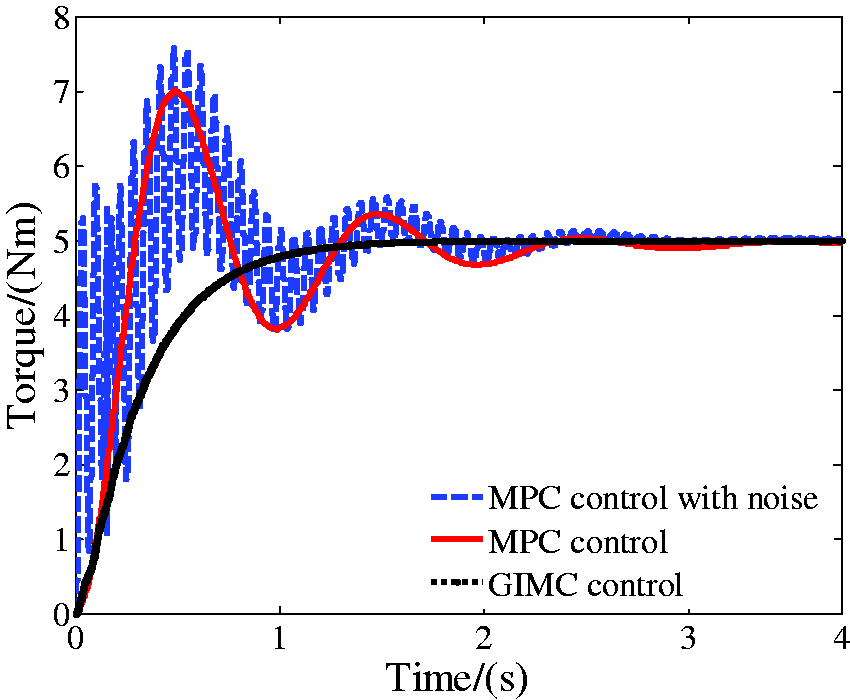
Torque sensor measurement.
Figure 10 shows that the response curve under the control of MPC generates a maximum of 40% overshoot at the time of 0.5 s, and gradually stabilizes after 2 s of oscillation, with a longer response time. The MPC control curve fails to resist noise and interference after noise occurs, resulting in continuous high-frequency oscillating and poor feeling of EPS system. Compared with those under the control of MPC, the response curve under the control of GIMC is characterized by being faster and more stable. Because the system can achieve a stable state at the time of 1 s and remove the influence of interference and noise on the system in an effective way. Therefore, the EPS system under the control of GIMC enjoys a better feeling.
Handling stability
The yaw rate is a significant indicator for measuring vehicle stability and EPS system performance. 18 In this paper, the yaw rate response under the control of MPC and that of GIMC is measured by applying a step response to the system and the vehicle speed is set to 30 m/s. The yaw rate’s response curve with two controls is obtained, as shown in Figure 11.

Response curve of yaw rate.
As the MPC is shortage on heavy computation, it is easy to produce hysteresis. From Figure 11, we know that the yaw rate with MPC fluctuated for the time of 2 s with a maximum of 20% overshoot in 1 s, which makes the steering stability of the vehicle poor. However, the yaw rate response under the control of GIMC is featured by being faster, and obtains the stable state in 1 s with more stable response without obvious overshoot. All this suggests that the EPS system has gotten a better handling performance making the vehicle possess a better handling stability.
Hardware-in-the-loop experiment
The GIMC controller has been verified to some extent in the simulation experiment. Furthermore, to verify the GIMC’s real effect, an EPS-based hardware-in-the-loop bench based on Dspace is set up,19,20 as shown in Figure 12. The GIMC controller is embedded in the bench. The author focuses on the current tracking ability. Therefore, the target current data and the actual one are collected under different control by ControlDesk.

EPS hardware in-loop experimental bench on the basis of Dspace.
Under the condition of in situ simulation, the input of the torque is obtained by the operator acting on the steering wheel and the torque values are measured by torque sensor which is applied to the calculation of target current value by the assist characteristic curve. The current sensor collects current from assist motor in real time. The controller obtains the input PWM of the motor by controlling the actual current’s error from the target one, therefore driving assist motor to generate the following response.21,22 Figures 13 and 14 show the current response curves under the control of MPC and GIMC, respectively.

Current response with MPC.

Current response with GIMC.
Figures 13 and 14 show that it is obvious for the actual current under the control of MPC to oscillate in the process of tracking the target current, and the actual tracking current generates obvious interference and noise with a poor effect in about 10 s and 15–20 s during which the target current changes violently. While the current tracking effect under the control of GIMC has more advantages, such as better tracking effect, filtering the influence of interference and noise to a certain extent, especially the local jump caused by the model uncertain, and making more stable curve response leading to obtain a good actual control performance.
Conclusion
This paper built the simulation model of Simulink, simulates the GIMC controller and compared it with the simulation experiment under the control of MPC. The results show that the controller was featured by better current tracking response, making the driver a good hand feeling and steering stability better, and as well as dealing with the model uncertain and interference and noise.
To verify the actual effect of the controller, this paper built an EPS-based hardware-in-the-loop experiment bench based on dSPACE, embedding the controller into the bench to explore the current tracking capability under real control conditions. The bench experiments were carried out under the MPC controller and the GIMC one, respectively, whose results showed that the GIMC controller obtains better current tracking capability and can deal with the model uncertain, interference and noise under the real condition to a certain extent making EPS have better robustness and stability.
This paper focused on the major factor on EPS performance in the course of the design of the controller, and system friction and heat loss was not considered. At the same time, the tire model was linear in the process of modeling. To be closer to the real situation, the nonlinear tire model will be selected in the future. Finally, the controller will be tested on the real vehicle on the basis of the reliability experiment of the controller.
Footnotes
Data availability statement
The experimental data used to support the findings of this study are available from the corresponding author upon request.
Declaration of Conflicting Interests
The author(s) declared no potential conflicts of interest with respect to the research, authorship, and/or publication of this article.
Funding
The author(s) disclosed receipt of the following financial support for the research, authorship, and/or publication of this article: The authors acknowledge the support from Natural Science Foundation of Shandong Province (ZR2016EEQ06).