
Abstract
In response to the influence of motor interference, damping, friction, and other uncertain factors on the operation of electric power steering systems under extreme working conditions, this study proposes a control strategy for electric power steering systems based on an active disturbance rejection algorithm. In ADRC, the fastest tracking differentiator is used to arrange the transition process for the target signal, and the extended state observer compensates for the total disturbance in the system. Phase compensation has been performed on the monitoring torque by using the torque differentiation method. The Simulink/Carsim simulation results show that ADRC has significantly improved anti-disturbance performance compared to PID and fuzzy PID. When using ADRC, the tracking accuracy of the assisted current is enhanced by 45.8%–75.8%, and the current adjustment time is reduced by 35.6%–61.7%. After phase compensation, the monitoring torque overshoot is reduced by 83.3%. Therefore, the proposed control strategy improves EPS’s robustness and steering feel.
Keywords
Introduction
Electric Power Steering system (EPS) has been widely used in passenger cars. 1 Compared to hydraulic power steering systems, EPS has the advantages of good steering following performance and low energy consumption. 2 The EPS control strategy directly determines the effectiveness of assistance. However, many uncertain factors in the actual driving process of the vehicle, such as road interference, motor dead zone, system friction, and other nonlinear factors, significantly increase the difficulty of control. Traditional PID control algorithm is difficult to meet the control requirements, so a controller that can quickly adapt to uncertain interference is needed for closed-loop control of EPS.
The core part of the EPS control strategy is the control of the assist motor. Currently, research on EPS control strategy mainly focuses on improving the control accuracy of the assist motor. To improve the tracking effect of assist torque, Murilo et al. Andre proposed an EPS control strategy based on parameterized model predictive control (MPC). 3 The MPC algorithm provided lower computational complexity, and the results showed that the control strategy had good torque tracking performance. Liu designed power compensation control and damping control strategies for the changes in control methods of heavy-duty vehicle EPS at different driving speeds, providing a theoretical basis for the development of heavy-duty vehicle EPS systems. 4 Whether using model predictive control or compensation control, the purpose is to improve the tracking effect of the assisted current. However, the target current is the most direct factor affecting the assisted current’s control effect in EPS. In the upper control strategy of EPS, the target current is jointly determined by the vehicle speed and monitoring torque. Considering the influence of damping, friction, and other factors on the steering column, monitoring torque values often exhibit significant fluctuations and phase lag. Therefore, phase lead compensation is required for the monitoring torque.
In practical engineering, most EPS motor control still uses PID controllers. PID controllers have simple control principles and reliable control effects, which are widely used in engineering. 5 Although traditional PID controllers are easy to adjust, their anti-disturbance ability is not ideal. To improve the adaptability of PID controllers, some scholars have combined fuzzy control theory with PID algorithms to design a fuzzy PID controller that can automatically modify PID control parameters, which to some extent, improves the robustness of the PID controller. 6 Although the fuzzy PID controller can adjust the control gain in real time based on errors and the rate of error change, fuzzy rules are usually designed based on engineers’ experience, and their parameter variation range is limited, so their suppression effect on uncertain disturbances is not outstanding. When there are uncertain disturbances in the system, the assisted current is prone to fluctuations due to disturbance, and the tracking performance of the current will also decrease. Therefore, we have conducted some research on anti-disturbance control of the system.
Disturbance suppression methods are usually divided into two categories: one is passive anti-disturbance control, including robust control, and sliding mode control. Jiang 7 takes the EPS of an electric forklift as the research object and proposes a robust controller optimized by a genetic algorithm. The designed controller has an obvious suppression effect on external disturbance. 7 Since EPS is vulnerable to the road and parameter disturbance, Lu 8 proposed an adaptive fuzzy sliding film control method. The simulation results show that the designed fuzzy sliding film controller is more stable than the sliding mode control and effectively reduces the disturbance caused by time-varying parameters. 8 Robust controller design usually considers the worst case of model uncertainty, and its dynamic response will not be particularly ideal. Considering that the response of the assist motor in EPS should be fast and accurate, robust control is difficult to meet the control requirements of EPS. 9 The sliding mode controller also has a good suppression effect on disturbances. However, the discontinuous switching of the sliding mode controller can easily cause system chattering. For the assist motor, the oscillation of the output torque will affect the driver’s sense of control. Another type of method is active anti-disturbance control. It is mainly achieved through disturbance observer (DOB), which can estimate and compensate for disturbances without affecting the system’s dynamic response. This type of method has obvious advantages in suppressing system disturbances. Therefore, active anti-disturbance control is more suitable to balance the dynamic response performance and anti-disturbance performance of EPS.
Compared with the traditional DOB control, the active disturbance rejection control (ADRC) inherits the characteristics of error elimination in PID control and arranges a transition process for the target signal. 10 Using the fastest tracking differentiator can effectively filter the noise in the target signal and improve the system control accuracy. Moreover, the extended state observer in ADRC can compensate for the errors and disturbances in the system modeling process. It can also estimate the disturbances effectively without relying on the accurate system model. Na designed a target torque algorithm based on steering wheel angle and angular velocity to reduce the impact of low-frequency disturbances on steering torque and used an active disturbance rejection controller to control motor torque. The simulation results show that the control method has a better control effect on torque stability than PI control. 11 To reduce disturbances caused by EPS modeling errors and nonlinear factors, Leng et al. designed a steering angle controller based on the active disturbance rejection algorithm, which effectively improves the tracking accuracy of the steering angle by using feedforward compensation and nonlinear state feedback law. 12 The above scholars have applied ADRC to the control strategy of EPS, and their research provides a theoretical basis for the feasibility of active disturbance rejection algorithms in EPS.
In summary, existing research on active anti-disturbance control of EPS could be better. To simultaneously meet the speed, accuracy, and robustness requirements of EPS, this study combines ADRC with the control of the assist motor in EPS. It proposes an assisted current control method based on ADRC. A second-order ADRC controller is designed, which includes a discrete fastest-tracking Differentiator, a linear error feedback control rate, and an extended state observer. At the same time, to improve the target current’s accuracy, this study uses the torque differentiation method for phase compensation of the monitoring torque. Finally, this article verifies the effectiveness of the designed control strategy through Simulink/Carsim joint simulation.
EPS working principle and composition
The EPS consists of an assist motor, a reduction mechanism, and ECU. The working principle and composition are shown in Figure 1. The torque sensor detects the torque transmitted by the steering wheel and sends the monitoring torque signal to the ECU. Then, the target assisted current is calculated from the power assist characteristic curve. After the ECU controls the target current, the assist motor outputs the corresponding assisted torque to assist the driver in steering. 13
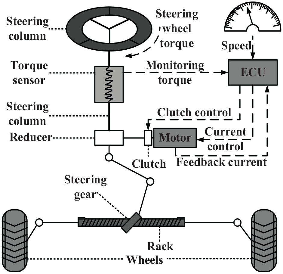
Working principle and composition of EPS.
Modeling of electric power steering system
Steering wheel and steering column
Take the steering wheel and steering column as a whole to establish the dynamic equation as shown in formula (1):

The monitoring torque can be expressed as the product of the difference in rotation angle and the stiffness of the torsion bar, and the monitoring torque equation can be obtained as shown in formula (2):

Assuming that the steering shaft and the steering gear pinion are rigidly connected, the output shaft angle can also be regarded as the pinion angle:
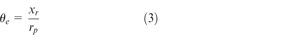
Where: Td is the input torque of the steering wheel; Ts is the monitoring torque; θc is the steering wheel angle; Jc is the moment of inertia of the steering wheel and steering shaft; Bc is the damping coefficient of the steering wheel and steering shaft; Ks is the stiffness of the torsion bar of the torque sensor; θe is the steering output shaft angle; xr is rack displacement; rp is the pinion radius.
Rack and pinion steering gear and return torque
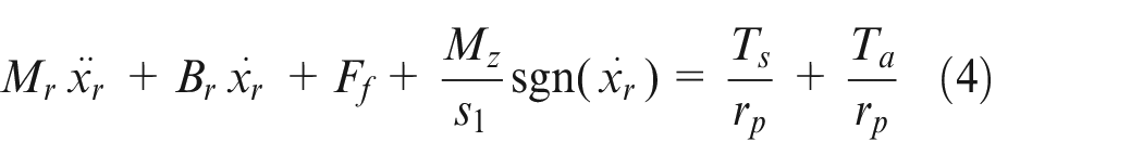
The torque acting on the steering wheel by the driver is transmitted to the rack and pinion steering gear through the steering column. 14 The assist torque provided by the assist motor also acts on the steering gear to overcome the steering resistance torque. This study considers the rack and pinion steering gear and the tire as a whole. After the force analysis, the balance equation is obtained as shown in formula (4):
The steering resistance torque is mainly composed of the self-returning torque and the internal friction resistance of the steering system. 15 The self-returning torque has two main factors: the caster angle and the kingpin inclination angle.
EPS self-returning torque consists of lateral self-returning torque and vertical self-returning torque:

The lateral self-returning torque caused by the lateral force around the kingpin is shown in formula (6):

The vertical self-returning torque caused by the vertical force around the kingpin is shown in formula (7):
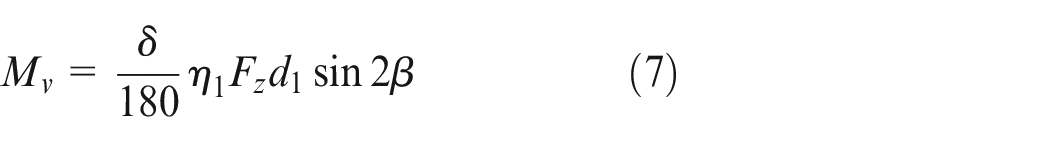
Where: Mr is the equivalent mass of rack and tire; Ff is the friction resistance of the steering system; Mz is the self-righting moment; s1 is the length of the steering knuckle arm; Br is the equivalent damping coefficient of gear and tire; Ml is the lateral self-returning torque; α is the caster angle of kingpin; β is the kingpin inclination angle; eη is the pneumatic trail; eτ is the caster moment arm; η1 is the reverse transmission efficiency of the steering system; Mv is the vertical self-returning torque; d1 is the distance from kingpin center to the wheel; Fz is the vertical force acting on the wheel; Fy is the lateral force acting on the wheel; δ is the front wheel deflection angle.
Assist motor
The assist motor adopts a permanent magnet brushless DC motor. It can be equivalent to a series structure composed of inductance, resistance, and controlled source when analyzing its circuit. The equivalent model is shown in Figure 2.
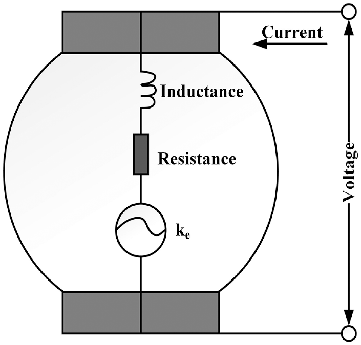
Equivalent model of the assist motor.
The equivalent controlled source is the motor back electromotive force, 16 which is proportional to the motor speed. According to the equivalent model, the motor loop equation can be obtained in formula (8):

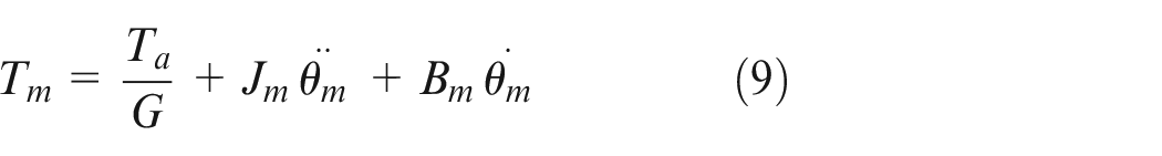
The dynamic model can be established by combining the mechanical part of the assist motor, as shown in formula (9):
The electromagnetic torque of the permanent magnet DC motor is proportional to the current, and formula (10) can be obtained:

The assist torque Ta acting on the steering shaft after being increased by the reducer can be calculated according to formula (11):

Where: U is the motor terminal voltage; R is the equivalent resistance of the motor; I is motor armature current; L is the equivalent inductance of motor armature; ke is the back EMF coefficient; θm is the motor angle; G is the transmission ratio of the reducer; ka is the electromagnetic torque constant of the motor; Ta is the assisted torque; Tm is the electromagnetic torque; Jm is the rotational inertia of the motor; Bm is the motor damping.
Electric power steering control strategy
EPS control principle
EPS is a servo system with the basic requirement of quickly, accurately, and stably tracking the target current I0. The basic control principle of EPS is shown in Figure 3.
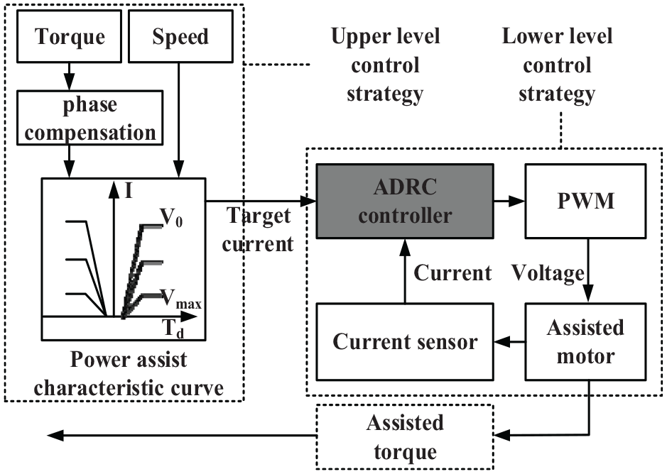
EPS control principle.
After the monitoring torque signal is phase compensated, the corresponding target assisted current is calculated from the power assist characteristic curve, and the target current of the motor is tracked and controlled by the ADRC controller. Then, the analog voltage obtained by the pulse width modulation (PWM) method is used as the motor input. The actual assisted current of the motor is fed back from the current sensor to the controller for closed-loop control. Finally, the assisted torque is output by the assist motor.
EPS power assist characteristic curve
EPS power assist characteristic curve can directly reflect the relationship between steering wheel torque and target assisted current under different vehicle speeds. The linear power curve adopted in this paper is shown in Figure 4.
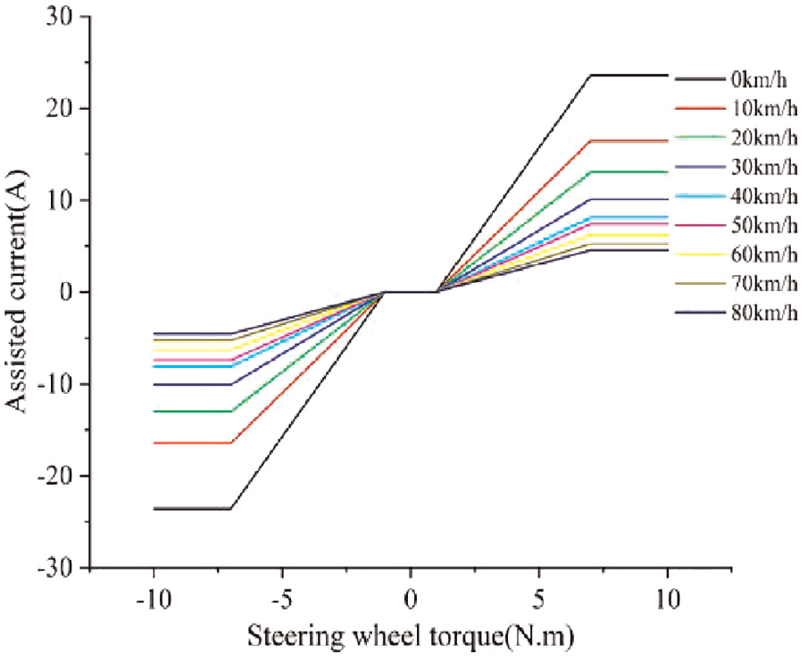
Power assist characteristic curve.
The curve has the following characteristics:
(1) The curve slope decreases with the increase in vehicle speed;
(2) When the steering wheel torque is in the range of [−1, 1] N·m, the assisted current is zero;
(3) When the steering wheel torque exceeds 7 N/m, the assisted current reaches the maximum value and does not change.
Active disturbance rejection controller
The control principle of the active disturbance rejection controller designed in this article is shown in Figure 5.
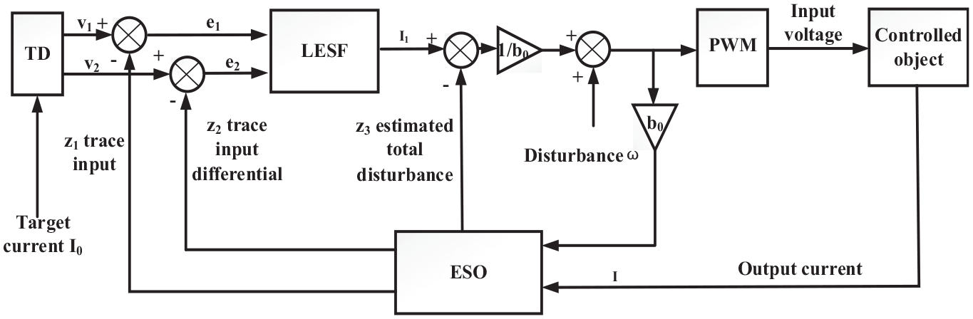
Control principle of active disturbance rejection controller.
First, by arranging the transition process, the target current signal I0 gets the input and differential signals through the discrete fastest tracking differentiator (TD). Then, the linear error state feedback control rate (LESF) combines the state errors e1 and e2 and forms a combined control rate to determine the error feedback control quantity I1. In the extended state observer (ESO), b0 is the feedback amplification coefficient, z1 tracks the input signal, z2 tracks the differential signal, and z3 tracks the total disturbance. Finally, ESO provides feedback compensation for errors and disturbances in EPS based on the input and output signals of the controlled object. The control algorithms for each part of the second-order ADRC controller are as follows:
(1) Discrete fastest tracking differentiator (TD)
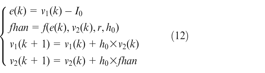
Where: e is the input signal error; I0 is the target current; fhan is the optimal control synthesis function; v1 is the input signal; v2 is the differential signal.
The function in fhan is shown in formula (13):
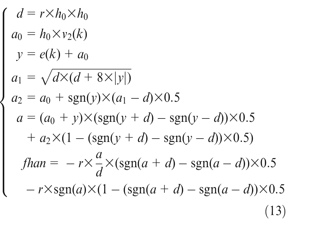
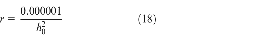
Where: The final output is the optimal control synthesis function fhan; d, a, y, a0, a1, a2 are intermediate variables; r is the speed factor, and its value reflects the signal tracking speed; h0 is the sampling step size, and reducing the sampling step size can suppress noise in the signal.
The purpose of using the discrete fastest tracking differentiator is to arrange the transition process, which can track the signal quickly without overshooting, expand the selection range of error feedback gain, and improve the robustness of the controller.
(2) Linear error state feedback control rate (LESF)

Where: β1 is the scaling factor; β2 is the differential amplification factor; e1 is the state error of the input signal; e2 is the state error of the differential signal.
The state errors e1 and e2 are combined by the linear error state feedback rate to improve the feedback efficiency, which is similar to the PD control, and has good robustness and adaptability.
(3) Extended state observer (ESO)
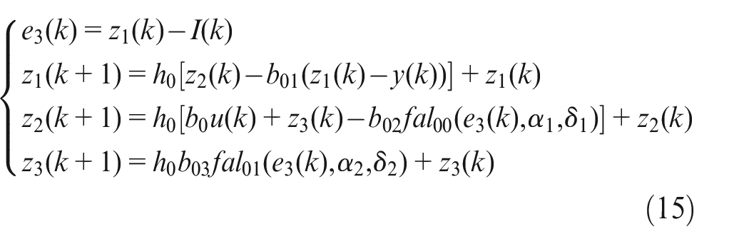
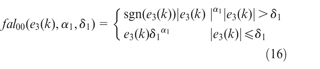
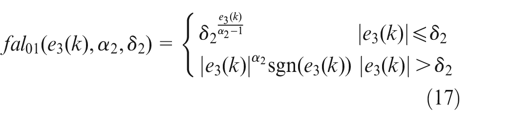
Where: b0 is the feedback amplification coefficient; e3 is the estimation error; b01, b02, and b03 are the control feedback quantities z1, z2, and z3 respectively corresponding to the gain parameters of the extended state observer; α1, α2 is the nonlinear factor in the fal function; δ1,δ2 is the interval length of the linear section
As the core part of ADRC, ESO does not rely on the model that generates disturbances to obtain disturbance estimates and can expand the uncertain parts and disturbances in the EPS model into new state variables, which has good robustness.
The parameter selection of ADRC directly affects the control effect of the system. According to the research conclusion of researcher Fang H in active disturbance rejection control technology, this study used a fixed sampling step method to determine the control parameters in TD. 17 The relationship between the speed factor and the sampling step size is shown in formula (18):
To select the control parameters of the extended state observer more conveniently, some scholars proposed a parameter tuning method based on the controller bandwidth. 18 The characteristic equation of the extended state observer of the second-order system is shown in formula (19):

Usually, when the form of the characteristic equation is (s+ω)3, the stability is good and can provide a good transition process. To make the state estimation of the controlled object more ideal, this article configures the control parameters b01, b02, b03 to the form of 3ω, 3ω2, ω3.
Where: s is the Laplace operator; ω is the controller’s bandwidth, it can be determined according to system requirements.
EPS phase compensation
In controlling the motor’s assisted current, it is necessary to output the analog motor voltage through the PWM module. The PWM module can be equivalent to the delay module, and its transfer function is shown in formula (20):
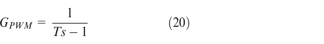
Where: T is the switching cycle, usually 1/20,000 s.
The presence of torque sensor signal acquisition, current loop, and PWM module will cause EPS torque output to fluctuate and delay to a certain extent, which is shown as slight shaking and abnormal noise of the steering wheel during steering. Therefore, it is necessary to improve system stability and response speed through certain phase compensation. To improve the phase margin of the system, the torque differential method is used to compensate for the monitored torque.
The actual differential transfer function used is shown in formula (21):
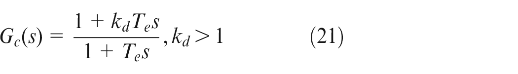
Where: Te is the differential time constant; kd is the differential gain.
Simulink/CarSim joint simulation
Simulink/CarSim software is used for joint simulation according to the mathematical model to verify the above EPS control strategy. The input signals of the EPS simulation model are the steering wheel torque signal and the vehicle speed signal. The CarSim vehicle model feeds back the left and right wheel state signals to estimate the resistance torque in real-time.
Control effect of ADRC controller
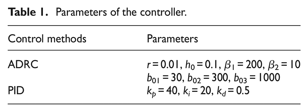
From Figure 6, it can be seen that TD has a good tracking effect on the input signal under step input and sinusoidal input, without overshoot, and is synchronized with the input signal. The estimation effect of ESO on the feedback value is in line with expectations. The parameters of the controller in the simulation are shown in Table 1.
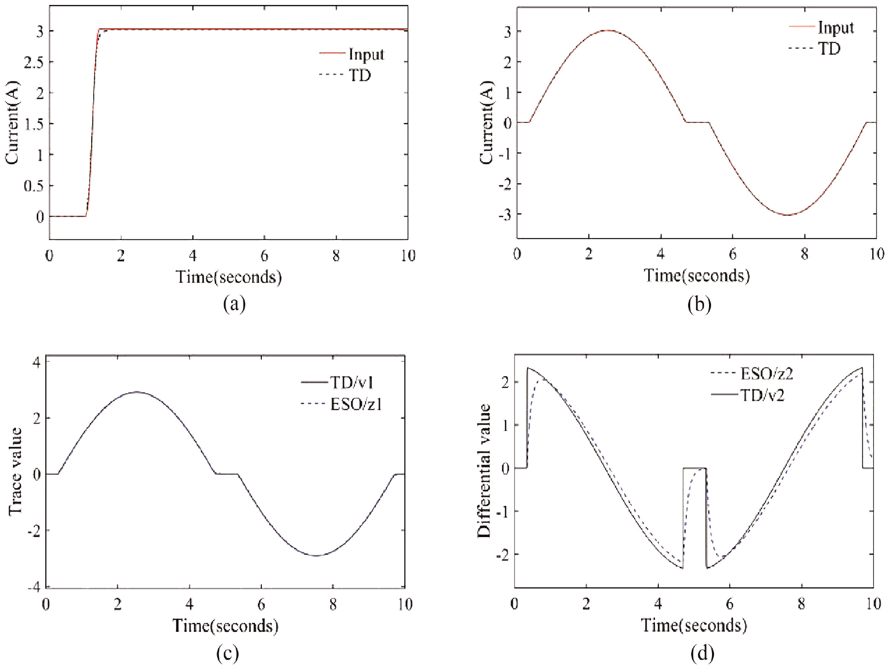
The signal tracking effect of TD and ESO without disturbance: (a) the tracking effect of TD on input signal under step input, (b) the tracking effect of TD on input signal under sinusoidal input, (c) estimation effect of feedback value z1 under sinusoidal input, and (d) estimation effect of feedback value z2 under sinusoidal input.
Parameters of the controller.
Set the vehicle speed to 10 km/h, and the motor control effect is shown in Figure 7:
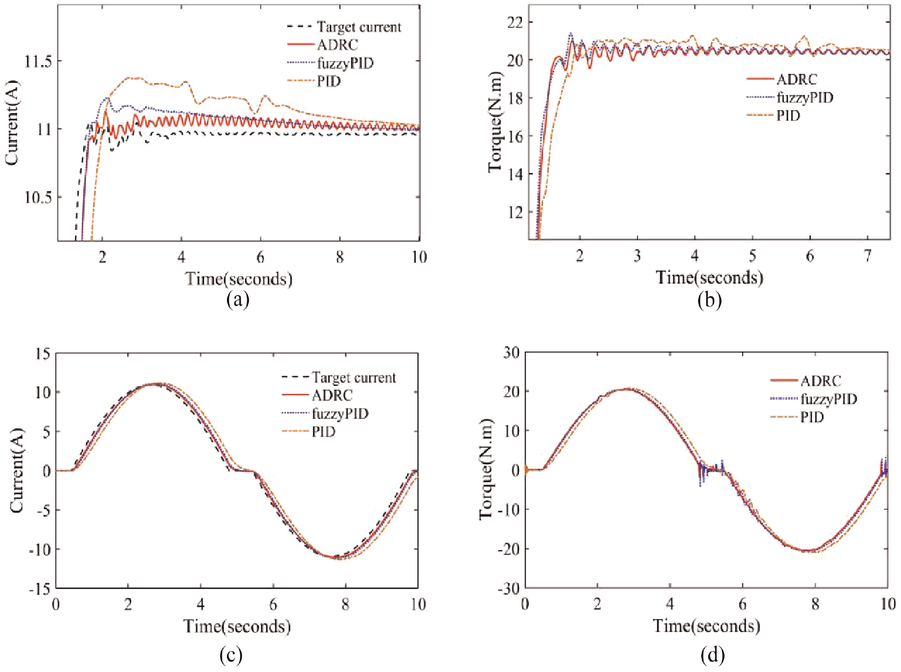
Control effect of the motor: (a) step response of assisted current, (b) step response of assisted torque, (c) sinusoidal response of assisted current, and (d) sinusoidal response of assisted torque.
The performance index of the current step response in Figure 7(a) is shown in Table 2.
Performance index of the current step response.
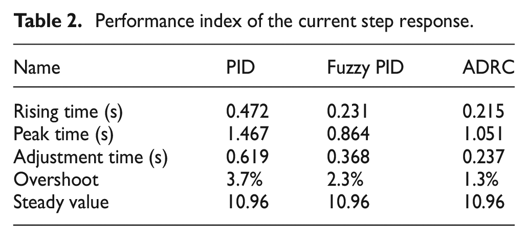
After combining Figure 7(a) and (b), it can be seen from Table 2 that the motor current has the minimum rising time and overshoot when using the ADRC controller. Compared to PID and fuzzy PID controllers, the ADRC controller reduces the adjustment time by 35.6%–61.7%, improving the response speed of assisted current and assisted torque.
This article defines the tracking effect coefficient of the signal as Kt, which can be calculated according to formula (22):
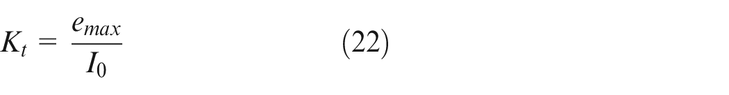
Where: emax represents the maximum error of current; I0 is the target current.
The tracking effect coefficients in Figure 7(c) are shown in Table 3.
Tracking effect coefficients.
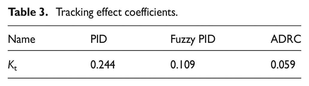
Figure 7(c) shows that when using a PID controller, the motor current tracking effect is poor and does not completely coincide with the target signal at the dead zone position. Under the sinusoidal input of steering wheel torque, the tracking accuracy of current using the ADRC controller is improved by 45.8%–75.8% compared to the PID controller and fuzzy PID controller. In Figure 7(d), when using a fuzzy PID controller, the motor torque fluctuates significantly in the assist dead zone. Compared to the fuzzy PID controller, the control effect of ADRC on the assisted torque is significantly improved.
Phase compensation effect
Set the steering wheel torque as step input and sinusoidal input respectively, and the phase compensation effect of the monitoring torque is shown in Figure 8.
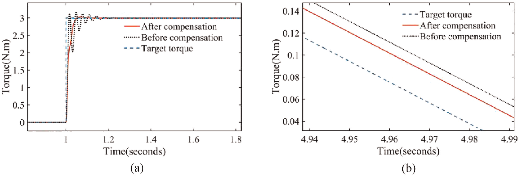
Phase compensation effect of monitoring torque: (a) step response of monitoring torque and (b) sinusoidal response of monitoring torque.
The performance index of step response in Figure 8(a) is shown in Table 4.
Performance index of monitoring torque step response.
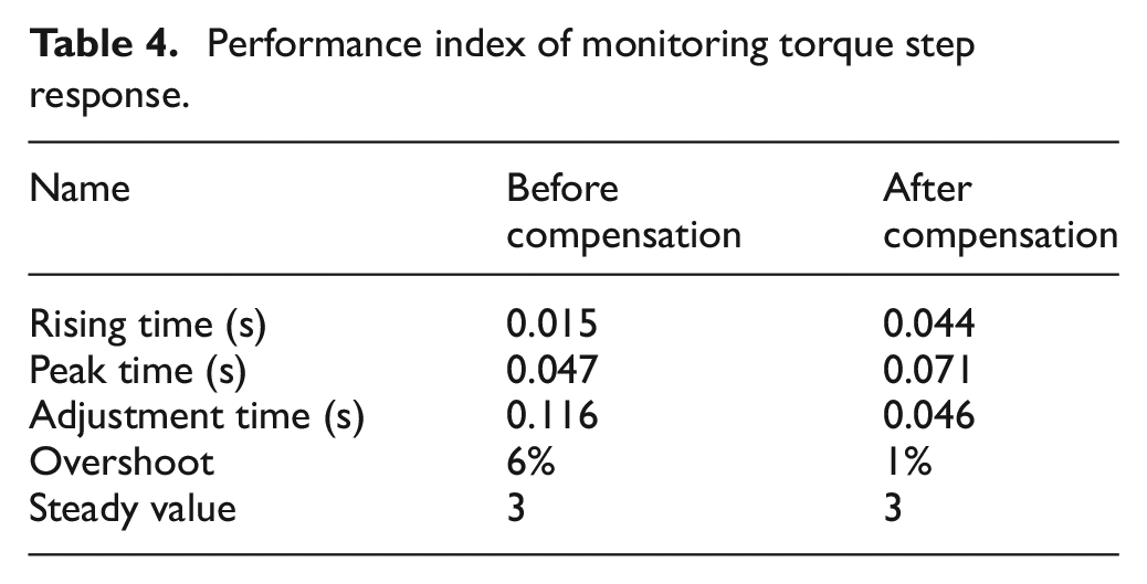
Based on Figure 8 and Table 4, it can be seen that there is low-frequency jitter in the monitoring torque before phase compensation. After phase compensation, the adjustment time for monitoring torque is reduced by 60.3%, tracking accuracy is improved by 25%, and overshoot is reduced by 83.3%. Phase compensation significantly reduces the oscillations during the response process, improving the system’s robustness.
It can be seen from Figure 9 that in the case of no interference, although the closed loop of the system is stable before compensation, the phase margin is too small. After phase compensation, the cut-off frequency of the system increases, and the phase margin is greater than 40°. The rapid response ability and stability of the system are improved.
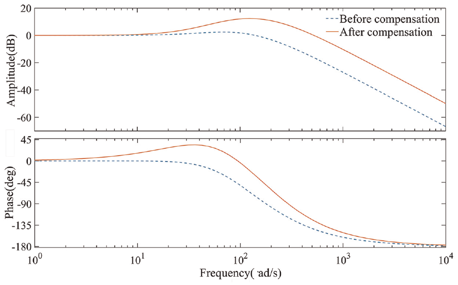
Bode diagram before and after phase compensation.
Anti-disturbance effect
When white noise and sinusoidal disturbance signals are added to the motor voltage, the anti-disturbance effect of the ADRC controller, fuzzy PID controller, and PID controller are shown in Figure 10. It can be seen from Figure 10 that the PID controller is very sensitive to disturbance signals, and whether it is sinusoidal disturbance or white noise will cause large fluctuations in the assisted current, which will seriously affect the control accuracy of the assisted current. The fuzzy PID controller has a certain inhibitory effect on disturbance signals, but the control effect still needs to be improved. When using the ADRC controller, the system output is minimally affected by disturbances, and the assisted current can effectively track the target signal, significantly enhancing the system’s anti-disturbance performance.
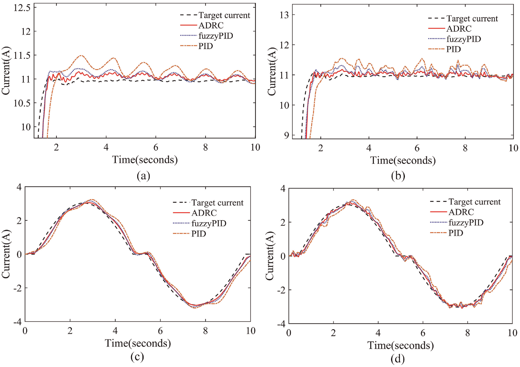
The anti-disturbance effect of ADRC, PID, and fuzzy PID: (a) step response of assist current when adding sinusoidal disturbance, (b) step response of assist current when adding white noise, (c) sinusoidal response of assist current when adding sinusoidal disturbance, and (d) sinusoidal response of assist current when adding white noise.
Steering feel simulation
To further verify the superiority of ADRC control, the double twisted wire simulation of the electric power steering system in this paper is carried out according to GB/T 6323-2014 test method for vehicle handling and stability.
The double-twisted wire simulation is shown in Figure 11. The steering wheel torque is sinusoidal input when the vehicle speed is 10 km/h. To simulate the system disturbance, this study adds white noise with a maximum amplitude of 5 and sampling time of 0.1 s to the motor voltage. The steering wheel angle increases correspondingly with the torque input. When using PID control, torque fluctuations are reflected on the steering gear, causing significant shaking of the steering wheel angle. After adopting ADRC control, there is a significant suppression of steering wheel shaking, making the steering process more stable and improving the EPS steering feel.
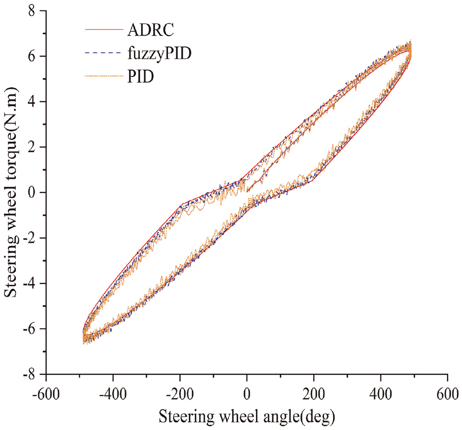
Double-twisted wire simulation.
Conclusion
To improve the anti-disturbance performance of the electric power steering system, this paper proposes an EPS assisted current controller based on an active disturbance rejection algorithm. The designed ADRC controller includes a discrete fastest tracking differentiator, linear error state feedback control rate, and extended state observer. Considering that the monitoring torque in EPS is affected by steering column damping and friction, which can cause jitter, this article conducts phase compensation for the monitoring torque. The tracking performance and anti-disturbance effect of PID, fuzzy PID, and ADRC were compared through Simulink/Carsim joint simulation.
The simulation results show that in the absence of disturbances, the dynamic response characteristics and tracking accuracy of ADRC are superior to PID and fuzzy PID controllers. When using an ADRC controller, EPS has good current tracking characteristics and slight torque jitter. Even under white noise or sinusoidal signal disturbance, the ADRC controller can still effectively track the target signal with good robustness. The monitoring torque has a minor overshoot and faster stabilization time after phase compensation, and the accuracy of the target current is improved. Therefore, it can be concluded that the proposed control scheme has good control accuracy and anti-disturbance ability, which can effectively enhance the EPS steering feel.
The electric power steering system designed in this study based on active disturbance rejection control meets the basic design requirements. In the next stage, compensation control will be applied to the front wheel angle of the vehicle for handling stability, and the control strategy will be further validated through hardware in the loop testing using Control Base.
Footnotes
Author contributions
Methodology, Z.Z.; software, J.W.; formal analysis, J.W.; resources, Z.Z.; data curation, J.W.; writing-original draft preparation, J.W.; writing-review and editing, Z.Z.; project administration, J.W.; funding acquisition, Z.Z. All authors have read and agreed to the published version of the manuscript
Declaration of conflicting interests
The author(s) declared no potential conflicts of interest with respect to the research, authorship, and/or publication of this article.
Funding
The author(s) disclosed receipt of the following financial support for the research, authorship, and/or publication of this article: This work was supported by the National Natural Science Foundation of China (51875494); the Natural Science Research Program of Jiangsu Province Colleges and Universities (19KJB580019); the Ministry of Education’s Industry School Cooperation Collaborative Education Project (202102427007); the Graduate innovation program of Yancheng institute of technology (SJCX22_XZ030)
Data availability and code availability statement
The data and code that support the findings of this study are available from the corresponding author upon reasonable request.
References
