
Abstract
Abstract
The application of Beidou Satellite Navigation System (BDS) is developing rapidly. To satisfy the increasing demand for positioning performance, single-frequency precise point positioning (SFPPP) has been a focus in recent years. By introducing the SFPPP technique into the INS/BDS integrated system, higher navigation accuracy can be obtained. Cycle slip, which is caused by signal blockage during the measurement of the carrier phase, is a challenge for SFPPP application. In the INS/SFPPP-BDS integrated system, cycle slip can cause serious bias in BDS carrier phase measurements. In this paper, a new INS/SFBDS-PPP tightly coupled navigation system and a robust adaptive filtering method are proposed. Using a low-cost single-frequency receiver integrated with INS, an observation model was built based on the pseudo range and carrier phase by PPP preprocessing. The cycle slip was introduced into the state vector to improve the estimation precision. The test statistics, comprising the innovation and its covariance, were used to estimate the time at which cycle slip occurred and its amplitude to compensate for its effect on the observation. Finally, the proposed system model and algorithm are validated by simulation.
Keywords
Introduction
With the development of Beidou Satellite Navigation System (BDS), the INS/GNSS integrated navigation technology has been applied in aerospace, surveying, and vehicle positioning.1–3 To satisfy the increasing demand for positioning performance, single-frequency precise point positioning (SFPPP) has been a focus in recent years.4,5 Unlike the traditional BDS positioning relay in the pseudo range and with only a pseudo range rate, the SFPPP introduces carrier phase measurements and information on the precise ephemeris and clock bias from the International GNSS Service (IGS), which reduce the measurement noise level and improve the positioning accuracy. 6 Thus, by introducing the SFPPP technique into the INS/BDS integrated system, higher navigation accuracy can be obtained.7–9
Cycle slip, which is caused by signal blockage during the measurement of the carrier phase, is a challenge for SFPPP application. In the INS/SFPPP-BDS integrated system, 10 cycle slip can cause serious bias in BDS carrier phase measurements. If carrier phase measurements with cycle slip were to be directly used in the fusion filter of the INS/SFPPP-BDS integrated system, the estimation would be incorrect, resulting in divergence of navigation results.11–14 Since signal blockage frequently occurs, particularly during the attitude maneuvering of aircraft or the operation of vehicles in an urban environment, the robustness of the INS/SFPPP-BDS to cycle slip must be improved.
In recent years, many methods have been studied to reduce the effect of cycle slip. To apply SFPPP to the tightly coupled INS/BDS system, the key point is to solve the problem caused by the cycle slip of the carrier phase. In INS/SFPPP-BDS, cycle slip introduces inaccuracies into the estimated INS errors in the system filter and thereby to the navigation results. Meanwhile, cycle slip detection and repair have become a major research focus. Hidekazu Machidam developed a remedy for phase error caused by cycle slip, with S-shaped drive pattern for smooth acceleration for dual-loop configuration and proposed a phase detector method caused by slip prevention using multi-state. 15 Ahmed El-Mowafy studied algorithms for detecting and repairing cycle slips and clock jumps using multi-constellation and multi-frequency GNSS data, which uses the average code and phase linear combination and applies to static data. 16 Zangeneh-Nejad et al. 17 proposed a method to fix cycle slips based on the generalized likelihood ratio (GLR) test. Teunissen studied the strength of the single-receiver, single-channel GNSS model for instantaneously resolving integer cycle-slips, including multi-frequency GPS, Galileo and BDS, thereby focusing on the challenging case that the slip is due to a simultaneous loss of lock on all frequencies. 18 Scholz 19 analyzed the performance for detecting and correcting cycle slips in carrier phase measurements in short signal outages situation in urban environments. Yousef et al. 20 developed a method to determine the change in the ionospheric and the code bias values from epoch to epoch by solving all observable equations using the least square technique, which could detect and predict cycle slip size of 1 cycle. Henkel and Oku 21 researched a cycle slips search method for double difference receivers and verified in both a slalom drive with high vehicle dynamics and a drive below trees with shadowed GPS signals. Liu 22 studied a cycle slip detection and repair method for a single dual-frequency GPS receiver; Cai et al. 23 studied cycle slip detection and repair for GPS without differential observations under high ionospheric activity; Tao studied the cycle slip detection and repair of Beidou; 24 and Huang et al. 25 studied a cycle slip algorithm validated with GPS data. These methods can detect and repair cycle slip to a certain degree.
However, for INS/SFPPP-BDS, the system filter works by continuous feedback correction, and the bias of the cycle slip repair will accumulate the effects of the INS error and cause navigation errors. Therefore, cycle slip and the integrated navigation system filter are important topics to address for INS/SFPPP-BDS.
In this paper, a new INS/SFPPP-BDS tightly coupled navigation system and a robust adaptive filtering method are proposed. Using a low-cost single-frequency receiver integrated with INS, an observation model was built based on the pseudo range and carrier phase by PPP preprocessing. The cycle slip was introduced into the state vector to improve the estimation precision. The test statistics, comprising the innovation and its covariance, were used to estimate the time at which cycle slip occurred and its amplitude to compensate for its effect on the observation. Finally, the proposed system model and algorithm are validated by simulation.
Observation model of SFBDS-PPP
General model
The observation vector of INS/SFPPP-BDS is composed of two parts: a pseudo-range observation, which is the difference between the code pseudo-range measurements from a BDS receiver and an equivalent pseudo-range of INS, and a half-sum observation, which is derived from the code pseudo-range and carrier phase.
The error of the pseudo-range and carrier phase measurements can be decreased by the IGS products. The clock error is eliminated by the IGS precise emphasis; the ionospheric error can be decreased by the grid layer model;26,27 the wet delay of the troposphere is estimated as a state of the system filter. The pseudo-range and carrier phase measurements of the BDS are shown in equations (1) and (2)


Improved model under the cycle slip effect
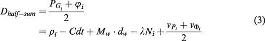
The half-sum model is used in the single-frequency PPP because it can eliminate the ionosphere delay. The ionosphere delay has opposite effects on the pseudo-range and carrier phase, as shown in equations (1) and (2), so the half-sum model can eliminate the ionosphere delay, as shown in equation (3)


Cycle slip compensation method
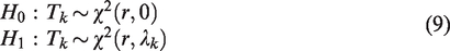
If there is no cycle slip, the innovation follows white noise, and the mean innovation is zero; when there is cycle slip, the mean innovation changes with the cycle slip. We define the hypothesis testing as follows: when no observation has faults, the hypothesis is


We use the innovation to construct the test statistics of the cycle slip detection

According to the characters of normal distribution and the matrix operation rules, under both the zero hypothesis and the alternative hypothesis,

Robust INS/SFBDS-PPP integrated method
System scheme design
The scheme of the INS/SFPPP-BDS tightly coupled navigation system is shown in Figure 1. In the proposed INS/SFPPP-BDS integrated navigation system, the INS is integrated with the SFPPP-BDS in a tightly coupled mode. The INS provides the attitude, velocity, and position results by the strapdown algorithm; the SFPPP-BDS provides the code pseudo-range and single-frequency carrier phase measurements. The IGS products such as the precise ephemeris and clock correction are synchronously received. This information will be transmitted to the system filter to construct the state model and observation model, based on which the state error estimation can be obtained to correct the INS and BDS in the feedback process.
The system observations consist of two parts: the pseudo-range observation, which is derived from the INS calculated pseudo-range and pseudo-range measurement from the BDS receiver, and the iono-free combination observation, which is derived from the half sum of the phase and pseudo-range. The system states also consist of two parts: INS errors and SFPPP-BDS positioning errors, which include receiver clock error, clock drift, tropospheric error, wet delay, integer ambiguity, and cycle slip.

Scheme of the INS/SFPPP-BDS tightly coupled navigation system.
Modeling for the INS/SFBDS-PPP integrated system
INS error state model
The system state model is given in equation (11)


The cycle slip state is modeled as a random constant, as shown in equation (13)


INS/SFPPP-BDS measurement model
The INS calculated pseudo-range can be obtained as follows

The observation model of INS/SFPPP-BDS is composed of a pseudo-range observation part and a half-sum observation part. The pseudo-range observation is the difference between the pseudo-range measurement of the BDS and the equivalent pseudo-range measurement of the INS; the half-sum observation is the linearization equation derived from the difference between the half-sum model and the equivalent pseudo-range measurement of the INS. The observation model is


The observation of the INS/SFPPP-BDS tightly coupled system changes as follows


The innovation of the Kalman filter is defined as equation (21)

Robust fusion algorithm

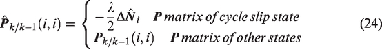
Assuming that a cycle slip occurs at epoch
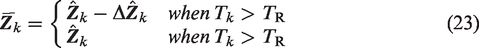
For matrix
Then, the adaptive filtering of INS/SFPPP-BDS follows as equations (25) to (29).


Simulation and analysis
Simulation parameter settings of the INS/SFBDS-PPP tightly coupled system.

Simulation of the INS/SFPPP-BDS tightly coupled system
In this section, the positioning accuracy performance of the proposed INS/SFPPP-BDS tightly coupled integrated navigation system is tested in the simulation. Compared with the traditional INS/BDS tightly coupled system, the INS/SFPPP-BDS system uses more accurate pseudo-range and half-sum observations by partially eliminating the BDS clock error, ionospheric error and tropospheric error. Therefore, the INS/SFPPP-BDS system has better positioning precision than the INS/BDS tightly coupled system. The navigation error comparisons of the INS/BDS and INS/SFPPP-BDS systems under identical simulation conditions are shown in Figures 2 to 4.
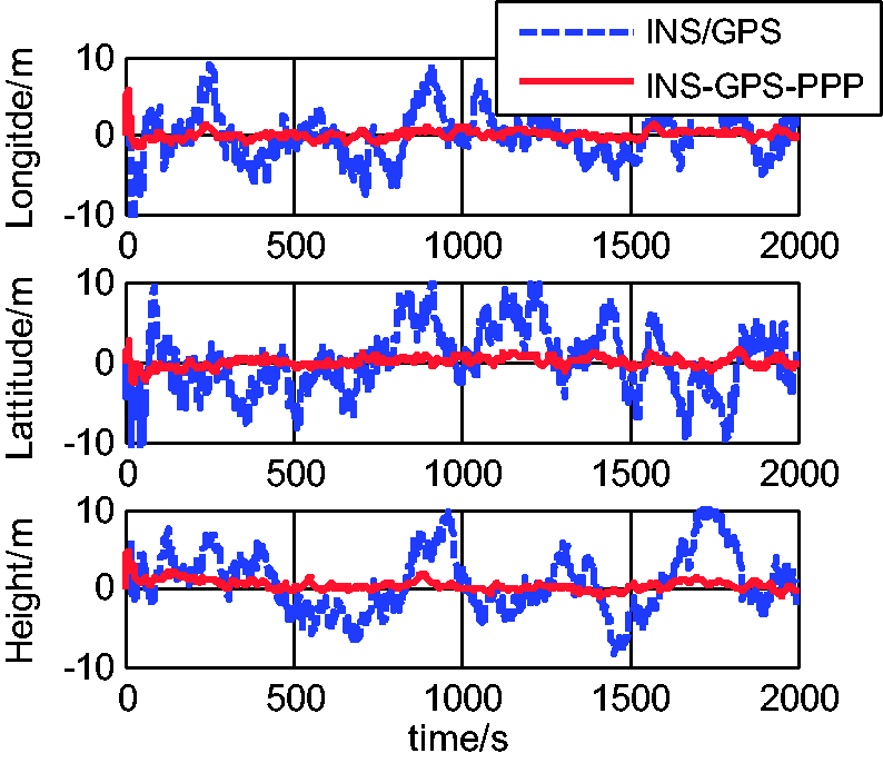
Positioning error comparison of INS/BDS and INS/SFPPP-BDS.

Velocity error comparison of INS/BDS and INS/SFPPP-BDS.

Attitude error comparison of INS/BDS and INS/SFPPP-BDS.
Comparison of the positioning error RMS values of INS/SFPPP-BDS and INS/BDS.

Comparison of the attitude error RMS values of INS/SFPPP-BDS and INS/BDS.

Comparison of the velocity error RMS values of INS/SFPPP-BDS and INS/BDS.
Simulation and analysis of the robust INS/SFPPP-BDS system with an adaptive cycle slip compensation model
Simulation settings of cycle slip.

The proposed robust algorithm with the adaptive cycle slip compensation model is applied to the INS/SFPPP-BDS system, and the simulation results are shown in Figures 5 and 6.
Observation errors of the visible satellites of the robust INS/SFPPP-BDS tightly coupled system with cycle slip. Test statistics of the cycle slip detection of the robust INS/SFPPP-BDS tightly coupled system.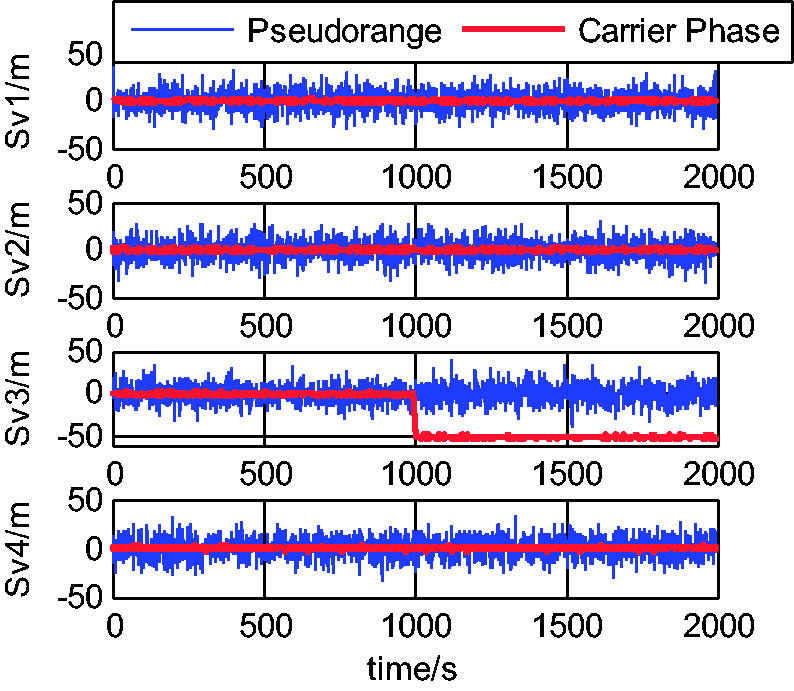

The curve of the carrier phase observations with cycle slip and the pseudo-range observations of the partially visible satellites is shown in Figure 5. The red solid line is the carrier phase observation, which has a cycle slip from 1000 s on Sv3, and the equivalent error of this cycle slip is approximately 50 m; the blue dash line is the pseudo-range observation, which is unacted on the cycle slip. Figure 6 shows the curve of the test statistics of the cycle slip detection in the robust INS/SFPPP-BDS tightly coupled system. The test statistics show that the curve has an abrupt change at 1000 s, which indicates that the cycle slip is correctly detected in real time.
The key point of compensating the cycle slip is that the cycle slip estimation should be consistent with the change innovation in the system filter, as shown in Cycle slip compensation method and Robust INS/SFBDS-PPP integrated method sections. When no cycle slip occurs, the innovation of the system filter follows white noise, and its variance is consistent with the observation variance. When cycle slip occurs, the innovation has an abrupt change, which should be compensated in time to avoid a huge positioning error and even the divergence of the system filter. The cycle slip estimation can resolve this problem. The innovation change and cycle slip estimation with the proposed robust integrated algorithm are compared in Figures 7 and 8.
Comparison of the observation innovation of INS/BDS with the robust INS/SFBDS-PPP tightly coupled system under the same cycle slip. Cycle slip estimation of the robust INS/SFBDS-PPP tightly coupled system.

The innovation of INS/BDS and the robust INS/SFPPP-BDS under identical cycle slips as shown in Figure 5 are given in Figure 7, and the corresponding cycle slip estimation curve is shown in Figure 8. The estimation of the cycle slip correctly follows the change of the innovation. Before 1000 s, the estimation should be approximately zero because no cycle slip has occurred; at 1000 s, the estimation value has an abrupt change, which is consistent with the innovation change in Figure 7. To dynamically compensate the innovation error, the introduction of this estimation as a system state into the INS/SFPPP-BDS filter will improve the navigation precision. In Figure 7, the red solid line is the compensated innovation of INS/SFPPP-BDS, and the blue dash line is the uncompensated innovation of the system. It shows that the compensation of the innovation is effectively.
Under the above conditions, the corresponding navigation results of the INS/SFPPP-BDS system with the proposed robust fusion algorithm and classic Kalman filter are given in Figures 9 to 11.
Positioning error comparison of INS/SFPPP-BDS with the robust fusion algorithm and Kalman filter. Velocity error comparison of INS/SFPPP-BDS with the robust fusion algorithm and Kalman filter. Attitude error comparison of INS/SFBDS-PPP with the robust fusion algorithm and Kalman filter.


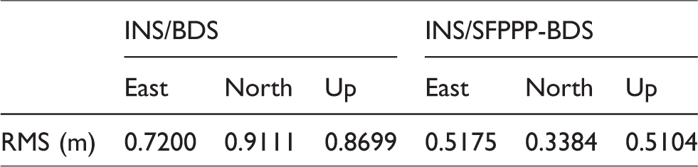
In Figures 9 to 11, the red solid line denotes the navigation results of the proposed robust INS/SFPPP-BDS, and the blue dash line denotes INS/SFPPP-BDS with the Kalman filter. Under the condition of cycle slip in Figure 5, the positioning error is seriously affected. The cycle slip occurs to Sv3 starting from 1000 s, which introduces approximately 50 m error into the observation. Figure 9 shows that the positioning error of the blue dash line significantly increases from 1000 s, whereas the red line has a stable positioning accuracy, and the positioning error is approximately 10 m during the entire navigation, even when the cycle slip occurs. Thus, the positioning precision is significantly improved, particularly during the stage when cycle slips occur, because the proposed robust adaptive algorithm uses the optimal estimation of the cycle slip to repair the cycle slip in the observation, and in the proposed algorithm, the parameter of the filter can be adjusted with the change in the cycle slip. Particularly after 1000 s, the positioning error of INS/SFPPP-BDS with the proposed algorithm is dramatically smaller than that with the Kalman filter. The RMS value of the positioning error is shown in Table 6. The comparison of the two results shows that the positioning accuracy can be significantly improved using the proposed algorithm.
Positioning error of INS/SFPPP-BDS with the Kalman filter and the robust navigation algorithm.

The RMS values of the attitude and velocity errors of the INS/SFPPP-BDS system are shown in Tables 7 and 8. Under the effect of the robust navigation algorithm, the precisions of the attitude and velocity measurements are also improved.
Attitude error of INS/SFPPP-BDS with the Kalman filter and the robust navigation algorithm.

Velocity error of INS/SFPPP-BDS with the Kalman filter and the robust navigation algorithm.

Conclusion
Because the positioning precision of the traditional INS/BDS tightly coupled integrated navigation system cannot satisfy the increasing requirement of high precision, a new scheme of the INS/SFPPP-BDS tightly coupled integrated navigation system and a robust adaptive filtering algorithm that can adaptively compensate the cycle slip are proposed in this paper. The pseudo-range and half-sum observation models are built, and the proposed robust INS/SFPPP-BDS tightly coupled navigation algorithm with the adaptive cycle slip compensation model is presented. The INS/SFPPP-BDS uses a single-frequency receiver to integrate with the INS and subsequently uses the IGS products to measure the pseudo-range and carrier phase to improve the observation accuracy. In the adaptive cycle slip compensation model, the error model of the cycle slip is introduced into the filter as a state to improve the cycle slip estimation accuracy; additionally, the optimal estimation of the cycle slip will help to adjust the filtering parameter to avoid filtering divergence. The innovation of the filter is used as a test statistic of the cycle slip detection to detect and repair the cycle slip in real time. The simulation results show that the performance of the cycle slip estimation relates to the amplitude and duration of the cycle slip. The simulation of the INS/SFPPP-BDS system with cycle slips shows that the proposed algorithm can significantly improve the positioning accuracy, and the accuracy of the attitude and velocity can also be improved.
Declaration of Conflicting Interests
The author(s) declared no potential conflicts of interest with respect to the research, authorship, and/or publication of this article.
Funding
The author(s) disclosed receipt of the following financial support for the research, authorship, and/or publication of this article: This work was partially supported by the Aeronautic Science Foundation of China (grant no. 20165552043), Science and Technology on Avionics Integration Laboratory.