
Abstract
Black-phase formamidinium lead iodine with 1.48 eV bandgap is considered to be the most promising material for improving the near-theoretical limit efficiency of perovskite solar cells, but at room temperature, black-phase formamidinium lead iodine easily transforms into the yellow non-perovskite phase formamidinium lead iodine. Here, different ratios of Cs+-incorporated formamidinium lead iodine prepared by one-step processing with the stability and power conversion efficiency of formamidinium lead iodine perovskite solar cells are investigated. FA0.85Cs0.15PbI3 shows the highest power conversion efficiency of 10.63% (Voc = 1.04 V, Jsc = 16.81 mA cm−2, and fill factor = 0.60), and the unencapsulated device maintained 60% of the initial power conversion efficiency after storage in air with 40% humidity for 186 h with an active area of 0.1 cm2, when the ratios of Cs+ reached 15% (x = 0.15) in formamidinium lead iodine. However, the efficiency of perovskite solar cell–based formamidinium lead iodine is still low. In this work, a simple but an effective strategy was carried out to rapidly and fully oxidize hole transport layer solution by doping CO2 or O2 under ultraviolet light irradiation to increase the conductivity of hole transport layer, thereby improving the power conversion efficiency of solar cells. The results show that FA0.85Cs0.15PbI3 solar cells by CO2-doped hole transport layer for 90 s exhibited the highest power conversion efficiency of 16.11% (VOC = 1.11 V, JSC = 19.73 mA cm−2, and fill factor = 0.74). The improved photovoltaic performance is attributed to CO2-doped spiro-OMeTAD increasing charge carrier density and accelerating charge separation, thereby inducing higher conductivity. CO2 or O2 doped can rapidly and fully oxidize spiro-OMeTAD, and reduce the solar cell fabrication time; it is beneficial to the commercial use of perovskite solar cells.

Introduction
Black-phase formamidinium lead iodine (α-FAPbI3) with about 1.48 eV bandgap is considered to be the most promising material for improving the near-theoretical limit efficiency of perovskite solar cells, attributed to its high carrier mobility, long diffusion length, and suitable bandgap,1–5 but at room temperature, α-FAPbI3 easily transforms into the yellow non-perovskite phase FAPbI3 because the large size of FA+, the phase transition, and the stability of α-FAPI3 perovskite limit its further development. 6 Therefore, the stability of perovskite FAPbI3 is very important for the high performance of perovskite solar cells. Many researchers made great efforts to stabilize the α-FAPbI3, such as incorporated small-sized MA+, Rb+, or Br− to the lattice of FAPbI3 to stabilize the perovskite phase, resulting in high-performance cation halide mixed FAPbI3 perovskite solar cells.7–9 However, the incorporation of MA+ and Rb+ might not overcome the stability of perovskite phase but lose the advantageous narrow bandgap of FAPbI3.10,11 Niemann et al. 12 reported the Cs ion incorporated into the MAPbI3 perovskite structure; the photovoltaic performance of Cs x MA(1−x)PbI3 solar cells was largely improved. Compared with the instability of organic ion groups, perovskite materials with some inorganic components show relatively stable characteristics. 13
Spiro-OMeTAD is one of the most common hole transport layer (HTL) materials due to its high energy level matching. However, it has low conductivity and hole mobility. 14 Therefore, researchers make great efforts to improve hole mobility, leading to higher conductivity of spiro-OMeTAD. Typically, spiro-OMeTAD paired with Li-TFSI, in which Li-TFSI acts as a dopant to stabilize the radical cation. 15 The most common method is oxygen doping. The oxidation process of spiro-OMeTAD: Li-TFSI solution is exposed to air and light, which usually takes more than 10 h or even 1 day and is strongly dependent on ambient conditions. Moreover, the oxidation process may result in the residue of unreacted reactants or harmful by-product remaining in the doped spiro-OMeTAD. So, the doping process is not controllable, and mixed stability is not high.16,17 Burschka et al. 18 reported Co(III) compounds as effective p-type dopants to tune the charge transport of spiro-OMeTAD and gained a champion power conversion efficiency (PCE) of 7.2%. Liu et al. 19 observed that the perovskite solar cells with spiro-OMeTAD HTL with the addition of PbI2 achieved a recorded PCE of 20.3% and acquired a stable PCE of 19.9% by optimizing its adding amount. So far, spiro-OMeTAD remains the material in demand for high-performance perovskite solar cells. Therefore, rapid and complete oxidation of spiro-OMeTAD HTL is very important to improve the performance of perovskite solar cells.
In this work, on the one hand, different Cs+ ratio–incorporated FAPbI3 prepared by one-step processing to stabilize perovskite phase FAPbI3 is reported. The introduction of Cs + significantly increased the stability and PCE of FAPbI3 perovskite solar cells. FA0.85Cs0.15PbI3 shows the highest PCE of 10.63% (Voc = 1.04 V, Jsc = 16.81 mA cm−2, and fill factor (FF) = 0.60), and the unencapsulated device maintained about 60% of the initial PCE after storage in air with 40% humidity for 186 h with active area of 0.1 cm2. On the other hand, a fast but effective strategy was carried out to rapidly and fully oxidize HTL solution by doping CO2 or O2 under ultraviolet light irradiation to increase the conductivity of HTL, thereby improving the PCE of solar cells. The results show that the efficiency of FA0.85Cs0.15PbI3 solar cells has greatly improved after the HTL was doped with CO2 or O2 at different time points. The FA0.85Cs0.15PbI3 solar cells fabricated using 90-s CO2-doped HTL exhibited highest PCE of 16.11% (VOC = 1.11 V, JSC = 19.73 mA cm−2, and FF = 0.74). The improved photovoltaic performance is attributed to CO2- or O2-doped spiro-OMeTAD increasing charge carrier density and accelerating charge separation, thereby inducing higher conductivity. CO2 or O2 doped can rapidly and fully oxidize spiro-OMeTAD, and reduce the solar cell fabrication time; it is crucial for the commercial use of perovskite solar cells.
Experimental details
Device fabrication
The Fluorine-doped Tin Oxide (FTO) glass (2 cm × 2 cm) was cleaned in acetone, isopropanol, and ethanol by sequential sonication for 30 min, separately, and dried under N2 flow, and then treated with UV-Ozone for 20 min. A 10-nm thickness of SnO2 layer was deposited on the clean FTO substrate via spin-coating of 50 µL 7.5 wt% SnO2 colloidal dispersion (Aldrich) solution at 4000 rpm for 30 s; the substrate was annealed on hot plate at 150°C for 30 min and then exposed to UV-Ozone for 20 min before spin-coating of perovskite solution. Perovskite solution was prepared via dissolving PbI2 (669 mg, Aladdin, 99.9%), Formamidinium Iodide (FAI) (248 mg, Aldrich 99.5%), and Dimethyl sulfoxide (DMSO) (0.2 ml, Aladdin, 99.9%) in N,N-Dimethylformamide (DMF) (0.8 ml, Aladdin, 99.8%). For FA(1−x)Cs x PbI3, we added corresponding amount of CsI (Aladdin, 99.9%) (0 mg, 18 mg, 36 mg, 56 mg, and 72 mg of CsI for x = 0, 0.05, 0.10, 0.15, and 0.20) instead of FAI. Fifty microliters of perovskite solutions was coated at 4000 rpm for 30 s, of which 200 µL chlorobenzene (Aladdin, 99.9%) was dropped on the rotating substrate after 10 s; then, the substrate was annealed on hot plate at 120 °C for 10 min. The coating process is completed in a nitrogen glove box. Spiro-OMeTAD:LiTFSI solution (100 mg, 99.98%, Aladdin) was made by dissolving spiro-OMeTAD in 1 mL of chlorobenzene (Aladdin, 99.8%) and 40 μL of Li-TFSI (Aladdin, 99.8%) solution (574 mg of Li-TFSI in 1 mL of acetonitrile) and 35 μL of 4-tBP (Aladdin, 99.8%). The mixed spiro-OMeTAD: LiTFSI solution was bubbled with CO2 and O2 under UV light (365 nm) for 30, 60, 90, and 120 s, separately. Therefore, CO2- and O2-doped spiro-OMeTAD solution was prepared. Then, the spiro-OMeTAD HTL was prepared via spin-coating spiro-OMeTAD solution at 4000 rpm for 30 s. Then, 80-nm gold electrode was deposited using a thermal evaporator. Finally, FTO/SnO2/perovskite/spiro-OMeTAD/Au perovskite solar cells were successfully prepared.
Characterization
The UV-Vis absorption spectra of FA(1−x)Cs x PbI3 films were characterized by UV-Vis spectrometer (U-3900, Hitachi). Scanning Electron Microscope (SEM) (S4800, Hitachi) was used to characterize the morphology of Cs+-incorporated FA(1−x)Cs x PbI3. The crystal structure, phase, and crystallinity were analyzed by the X-ray diffraction (XRD) (D8 Germany, Bruker Axs). The room-temperature photoluminescence (PL) spectra were analyzed by fluorescence spectrophotometer (F-4600, Hitachi) with Ar laser (325 nm) as excitation source. Current density–voltage characteristics (J-V curves) were measured using a Keithley 2400 source meter under one-sun illumination (AM 1.5G, 100 mW cm−2) equipped with 450 W Xenon lamp (Newport). As for the perovskite solar cell stability in air, perovskite solar cells were stored in air with 40% humidity; the current density–voltage curves were tested every 24 h for about 186 h at room temperature about 25 °C.
Results and discussion
Figure 1(a) shows XRD patterns of FA(1−x)Cs x PbI3 films with different Cs ratios spin-coated on SnO2 films. It can be seen that all FA(1−x)Cs x PbI3 films show diffraction peaks at 14.0°, 19.0°, 24.2°, and 28.2°, which can be indexed to perovskite phase FAPbI3 (α-phase or black-phase FAPbI3) diffraction peaks of (100), (110), (111), and (200) planes, respectively. 20 Besides, a peak appeared at about 13° for unreacted PbI2. 12 For pristine FAPbI3, the diffraction peak of non-perovskite δ-phase near 12° still exists.21,22 However, there is only pure FAPbI3 perovskite phase in Cs+-incorporated samples. Moreover, the typical (110) peak of α-phase FAPbI3 shifts to higher angles with higher Cs+ ratios corresponding to smaller lattice constants, which proves that Cs+ is successfully incorporated into FAPbI3. 23 As all known, the FA+ radius is 0.253 nm and the Cs+ radius is 0.167 nm; the lattice constant of the mixed phase becomes smaller with the doping of small ion radius Cs+. 24 When the doping amount of Cs+ reached 20% at % (x = 0.2), a new diffraction peak appeared at 22.4°, which is due to formation of CsPbI3. 25 The shrinkage of lattice constant for A-site cation results in stronger interaction between A-site cation and iodide and probably results in the stability of FAPbI3. 26 The stability of perovskite materials is very important in the application of solar cells. Tolerance factor (t) is widely used to measure the stability of perovskite as proposed by Goldschmidt; Goldschmidt tolerance factor is calculated by the following formula 27


(a) XRD pattern; (b) tolerance factor; (c) UV-Vis absorption spectra; and (d) PL spectra of FA(1−x)Cs x PbI3 (x = 0, 0.05, 0.10, 0.15, and 0.20).
where rA is the radius of A-site ion, rB is the radius of B-site ion, and rx is the radius of X-site ion. The tolerance factor of FAPbI3 perovskite doped with different amounts of Cs+ is calculated to judge the perovskite structural stability of α-phase, and the results are shown in Figure 1(b), of which the ion radius of FA+, Cs+, Pb2+, and I− is 0.253, 0.167, 0.133, and 0.203 nm, respectively. It can be seen from Figure 1(b) that the tolerance factor of FAPbI3 is 0.966, which is close to the upper limit of α-phase, so maybe the stability of FAPbI3 is the worst. 28 The tolerance factor is 0.957, 0.950, 0.940, and 0.933 when the ratios of Cs ion are 5%, 10%, 15%, and 20%, respectively. With the increase in Cs+ content, the tolerance factor of perovskite decreases gradually. The Cs+-incorporated FAPbI3 shows a more stable α-phase, resulting in better stability of perovskite solar cells. 29 Li et al. 30 have reported that an effective tolerance factor of around 0.95 was beneficial to maintain a perovskite structure and which will be proved by perovskite solar cell stability test in the following. Figure 1(c) displays UV-Vis absorption spectra of FA(1−x)Cs x PbI3 films. It can be seen that all FA(1−x)Cs x PbI3 films have a strong absorption in the range of 600–830 nm. FAPbI3 film shows low absorption intensity due to pristine FAPbI3 with non-perovskite phase components. The absorption spectra increase with the increase in Cs+ ratios. The absorption of FA0.85Cs0.15PbI3 film reaches the maximum with the incorporated amount of Cs ion reaches 15%. With the increase in Cs+ ratios, the perovskite phase stability of FA(1−x)Cs x PbI3 films gradually increases, so the light absorption intensity increases. The stronger the light absorption intensity of perovskite film light absorption layer, the higher the photoelectric conversion efficiency. When the doping amount of Cs reaches 20% (x = 0.20), due to the formation of CsPbI3, the UV-Vis absorption spectrum is weakened. 21 On the contrary, there is a blue shift in UV-Vis absorption spectra of FA(1−x)Cs x PbI3 films with the increase in Cs+ ratios. With the increase in Cs content, the average size of A-site cations decreases proved by SEM images shown in Figure 2, leading to the decrease in the lattice constant of the film and the widening of the bandgap, so the absorption peak of the film shifts to blue. 24 PL spectra of FA(1−x)Cs x PbI3 film shown in Figure 1(d) display a blue shift with the increase in Cs+ ratios. FA0.85Cs0.15PbI3 film has a blue shift of about 10 nm compared with pristine FAPbI3, which shows that the bandgap becomes wider with the increase in Cs ion ratios. The result is consistent with UV-Vis absorption spectra.
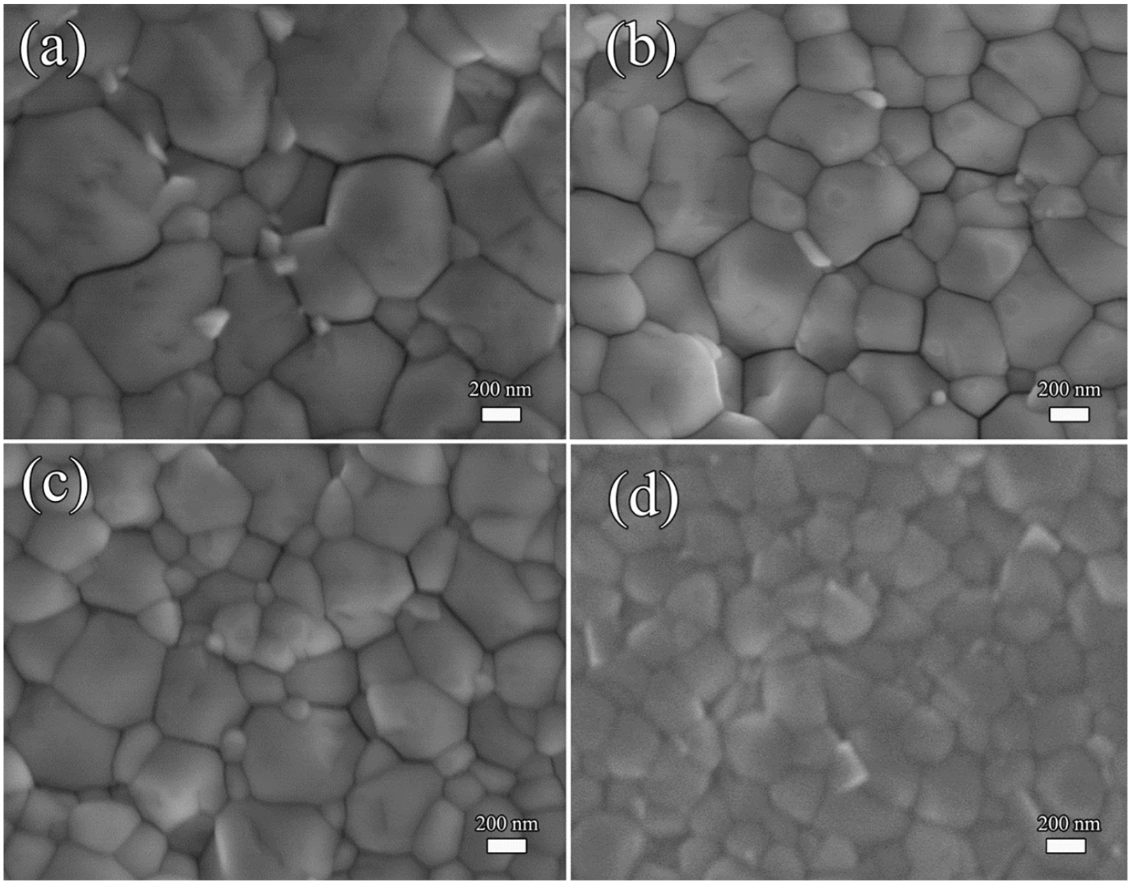
The SEM image of FA(1−x)Cs x PbI3 films with different Cs+ ratios of (a) x = 0.05; (b) x = 0.10; (c) x = 0.15; and (d) x = 0.20.
Figure 2 displays the SEM images of FA(1−x)Cs x PbI3 films incorporated with different Cs+ ratios of (a) x = 0.05, (b) x = 0.10, (c) x = 0.15, and (d) x = 0.20, which shows that the grain radius gradually decreases with the increase in Cs+ ratios. The crystal crystallization speed will become faster with the increase in Cs+ ratios and lead to a smaller grain size. 31 At the same time, the higher the Cs+ ratios, the weaker the light absorption capacity of the film. This result is consistent with that of XRD, UV-Vis absorption spectra, and PL spectra of FA(1−x)Cs x PbI3 films. Combined with XRD, UV-vis absorption spectra, and PL results, the obtained optimal doping amount of Cs+ is 15% (x = 0.15).
Figure 3(a) shows the schematic diagram of a perovskite solar cell device including of a transparent conductive oxide FTO, the ETL, the FA(1−x)Cs x PbI3 perovskite layer, the HTL, and a top Au electrode. Figure 3(b) is the cross-sectional SEM image of prepared FA0.85Cs0.15PbI3 perovskite solar cell device, which shows the FTO/SnO2/perovskite/Spiro-OMeTAD/Au, with a thickness of Au electrode of about 80 nm, HTL of about 200 nm, perovskite layer of 500 nm, and ETL of 10 nm, was successfully prepared. In order to verify the influence of Cs+ on the photovoltaic performance of perovskite solar cell, the photocurrent density–voltage (J-V) curves of FA(1−x)Cs x PbI3 perovskite solar cell were evaluated under simulated one-sun illumination at room temperature in air under relative humidity about 40% with 0.1 cm2 areas as shown in Figure 3(c), and Table 1 summarizes the corresponding photovoltaic characteristic parameters including open-circuit voltage (Voc), short-circuit density (Jsc), FF, and PCE. The PCE of pristine FAPbI3 is really low, only 3.12%, but the PCE increases with the increase in Cs ion ratios. Best performing FA0.85Cs0.15PbI3 perovskite solar cell shows 10.63% PCE (Voc = 1.04 V, Jsc = 16.81 mA cm-2, and FF = 0.60). It is mainly attributed to the fact that the addition of Cs ion as an inorganic ion enhances the stability of FAPbI3 perovskite phase in the humidity environment and makes the crystallization of more dense, reduces the influence of water, reduces the defects of the film, and reduces the recombination of carriers in the FAPbI3 perovskite layer, leading to increasing the short-circuit current and FF. Therefore, the PCE of the device is improved. 21 However, when the Cs+ ratio reaches 20% (x = 0.20), the PCE of solar cells decreases. With the higher Cs ions, the bandgap of mixed perovskite increases and the absorption peak shifts to blue and absorption intensity decreases; as a result, the ability of perovskite film to capture sunlight is weakened. Therefore, the PCE decreases, which is consistent with XRD, tolerance factor, and UV-Vis absorption spectra result. 32 Besides high performance, long-term stability of solar cells is also important. The stability of FA(1−x)Cs x PbI3 solar cells was evaluated. The devices were stored in ambient condition with 40% relatively humidity for 1 week; the photovoltaic performance of FA(1−x)Cs x PbI3 solar cells was measured every 24 h. The normalized PCE as a function of time is shown in Figure 3(d), PCE for pristine FAPbI3 perovskite solar cell was degraded by 90% after 48 h, Cs+ incorporated with 5% (x = 0.05) and 10% (x = 0.10) at % shows 90% degradation after 168 h, while Cs+ incorporated with 15% (x = 0.15) and 20% (x = 0.20) at % can still maintain over 60% PCE of the initial value after 168 h of storage at ambient condition with 40% relatively humidity conditions. The stability of FA(1−x)Cs x PbI3 solar cells has been gradually improved with the increase in Cs+ ratios, the enhanced stability in ambient condition is likely to be the phase stability, and the result is consistent with XRD result. 33 Based on the experimental results, the optimum Cs ion-doping ratios in FA(1−x)Cs x PbI3 solar cells are 15% (x = 0.15), that is, FA0.85Cs0.15PbI3. In fact, FA0.85Cs0.15PbI3 perovskite solar cell shows a limited PCE of 10.63% (Voc = 1.04 V, Jsc = 16.81 mA cm−2, and FF = 0.60).

(a) Schematic diagram of a conventional perovskite solar cell device; (b) the cross-sectional SEM image; (c) J-V curves; and (d) the stability of FA(1−x)Cs x PbI3 (x = 0, 0.05, 0.10, 0.15, and 0.20) perovskite solar cell.
Performance parameters of FA(1−x)Cs x PbI3 (x = 0, 0.05, 0.10, 0.15, and 0.20) perovskite solar cells.

FF: fill factor; PCE: power conversion efficiency.
Next, a fast and an effective method to oxide HTL doped by CO2 or O2 under ultraviolet light used to enhance conductivity of HTL leading to high-performing solar cells is investigated. The FA0.85Cs0.15PbI3 solar cells were fabricated with spiro-OMeTAD doped by CO2 or O2, using 20 m3 h−1 CO2 or O2 gas flow bubbled spiro-OMeTAD solution under ultraviolet light with 365 nm wavelength for 30, 60, 90, and 120 s, respectively. J-V characteristics of CO2- or O2-doped FA0.85Cs0.15PbI3 solar cells measured under simulated AM 1.5G solar irradiance (100 mW cm−2) are illustrated in Figure 4(a) and (b), and the corresponding photovoltaic characteristic parameters are summarized in Tables 2 and 3. For the undoped HTL solar cells, it is found that VOC, JSC, and FF are 1.06 V, 16.81 mA cm−2, and 0.60, respectively, achieving a PCE of 10.63%. This device suffers from a low FF due to the low conductivity of the undoped spiro-OMeTAD film, thereby results in a high series resistance. 14 The solar cell with an O2-doped HTL shows an improved photovoltaic performance, a champion device performance for solar cell doped with O2 for 90 s, exhibiting a PCE of 15.07% (VOC = 1.08 V, JSC = 20.44 mA cm−2, and FF = 0.69). Moreover, the HTL of solar cell doped with CO2 for 90 s reaches a PCE of 16.11% (VOC = 1.11 V, JSC = 19.73 mA cm-2, and FF = 0.74), which is higher than the O2-doped HTL solar cell. The results may be attributed to the fact that the solvent used in spiro-OMeTAD solution is chlorobenzene, while CO2 has higher solubility in chlorobenzene than O2. The high solubility makes CO2 react more fully with spiro-OMeTAD solution than O2 in the process of rapid reaction.34,35

(a) J-V curves of FA0.85Cs0.15PbI3 perovskite solar cell with HTL doped by CO2 at different time points; (b) J-V curves of FA0.85Cs0.15PbI3 perovskite solar cell with HTL doped by O2 at different time points; (c) PL spectra of pristine spiro-OMeTAD and CO2 doped at different time points (0, 30, 60, 90, and 120 s), and the inset one shows corresponding photographs.
Performance parameters of CO2-doped spiro-OMeTAD HTL in FA0.85Cs0.15PbI3 perovskite solar cells.

FF: fill factor; PCE: power conversion efficiency.
Performance parameters of O2-doped spiro-OMeTAD HTL in FA0.85Cs0.15PbI3 perovskite solar cells.
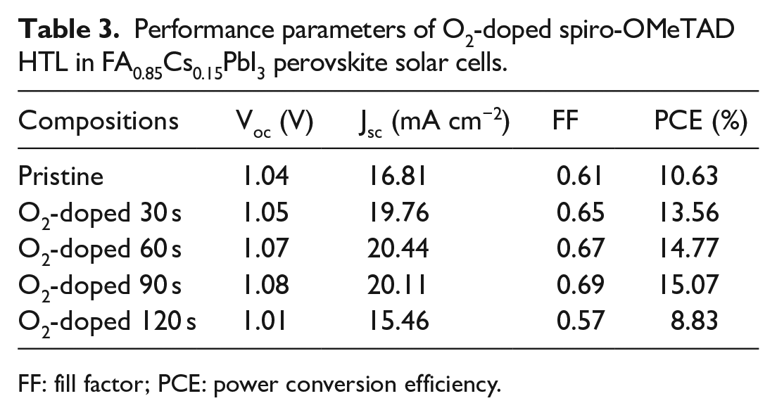
FF: fill factor; PCE: power conversion efficiency.
On the basis of experimental results, the improved photovoltaic performance of CO2 or O2-doped FA0.85Cs0.15PbI3 solar cells may be explained as follows: First, in our experiment, spiro-OMeTAD HTL bubbled by CO2 or O2 with 20 m3 h−1 gas flow under ultraviolet light with 365 nm wavelength for 30, 60, 90, and 120 s, respectively. Here, the ultraviolet light of 365 nm wavelength with energy of 3.4 h−1 eV, which is above the band gap of spiro-OMeTAD at about 3 h−1eV, 36 when spiro-OMeTAD is irradiated with a ultraviolet light of 365 nm generates an electron–hole couple; at the same time, CO2 or O2 was bubbled into spiro-OMeTAD solution, and CO2 or O2 obtains electron from photoexcited spiro-OMeTAD. The lowest unoccupied molecular orbital (LUMO) of spiro-OMeTAD (−2.05 eV) is above the reduction potential E0 = −1.90 V versus standard hydrogen electrode, so the spiro-OMeTAD can be oxidized and additional charge carriers (holes) created, resulting in an improved charge carrier density. Besides, electron transfer from spiro-OMeTAD to CO2 or O2 accelerates charge separation, so non-radiative recombination is limited, thereby inducing higher conductivity. 37 The PL spectra of spiro-OMeTAD HTL bubbled by CO2 under irradiation of ultraviolet light used to investigate the charge carrier dynamics, as shown in Figure 4(c), show observably quenched PL emission compared to that without CO2-doped spiro-OMeTAD. This result demonstrates a resonance energy transfer between donor and acceptor. In our experiment, there is electron transfer between the spiro-OMeTAD donor and the CO2 or O2 acceptor, thereby inducing an increase in charge separation and enhancing conductivity of spiro-OMeTAD HTL. 38 The inset of Figure 4(c) shows photographs of the CO2-doped spiro-OMeTAD solutions at different time points. The color of the spiro-OMeTAD solution becomes brown after being doped with CO2, the color being the characteristics of oxidation of spiro-OMeTAD of color. 39 The increase in conductivity of spiro-OMeTAD is beneficial for practical application, which is also proved by an improved photovoltaic performance of the solar cell doped with CO2 or O2. Besides, for CO2-doped HTL solar cell, upon the CO2-doped time of 30, 60, and 90 s, the PCE improves to 12.03%, 13.13%, and 16.11%. But when CO2-doped time reaches 120 s, respectively, the PCE decreases to 7.23%, which may be attributed to the transition oxidation of spiro-OMeTAD solution caused by too long reaction time. 40 At high doping levels, the hole density in the spiro-OMeTAD is higher; the higher hole density may increase recombination probability between hole and conduction band electron and consequently leads to a decrease in Voc.41–43 Generally, spiro-OMeTAD will add lithium salt to improve the conductive ability of HTL, which causes instability of solar cell due to the ease of lithium ion to reunite and high water imbibition that seriously limits the efficiency of solar cells. In CO2-doped spiro-OMeTAD HTL, CO2 will react with Li ions and produce relatively stable Li2CO3 salts after CO2 obtains electron from photoexcited spiro-OMeTAD, which reduces the density of lithium ions in the HTL, resulting in enhancement of the PCE and reliability of the solar cells. Kong et al. 39 reported a systematically study on CO2-doped organic interlayers for perovskite solar cells. Moreover, for CO2- or O2-doped spiro-OMeTAD HTL, CO2 or O2 can rapidly and fully oxidize spiro-OMeTAD; there is only 90 s in our experiment. In the conventional oxidation process, the spiro-OMeTAD solution is exposed to air for a long time, that is, more than 12 h, and the oxidation degree of spiro-OMeTAD strongly depends on the ambient conditions. Therefore, it is beneficial for the commercial use of perovskite solar cells by reducing the solar cell fabrication time.
Conclusion
In summary, the perovskite phase FA(1−x)CsxPbI3 films with different Cs+ ratios of 5%, 10%, 15%, and 20% (x = 0.05, 0.10, 0.15, and 0.20) at % were prepared by one-step processing method. The PCE and stability of FA(1−x)Cs x PbI3 solar cells has been gradually improved with the increase in ratios of Cs, and the enhanced stability in ambient condition is likely to cause phase stability, and the result is consistent with XRD and calculated tolerance factor result. The optimum Cs ion-doping ratios in FA(1−x)Cs x PbI3 solar cells are 15% (x = 0.15) with PCE of 10.63% (Voc = 1.04 V, Jsc = 16.81 mA cm−2, and FF = 0.60); the unencapsulated device maintained 60% of the initial PCE after storage in air with 40% humidity for 186 h with 0.1 cm2 area. In fact, FA0.85Cs0.15PbI3 perovskite solar cell shows a limited PCE of 10.63%, so a fast and an effective method to oxide spiro-OMeTAD HTL, doped by CO2 or O2 under ultraviolet light irradiation from 0 to 120 s, is investigated. The results show that the PCE of FA0.85Cs0.15PbI3 solar cells has greatly improved after the HTL was treated with CO2 or O2. The FA0.85Cs0.15PbI3 solar cells fabricated using 90 s CO2-treated HTLs exhibited highest PCE of 16.11% with opening voltage VOC = 1.11 V, short-circuit current JSC = 19.73 mA cm−2, and filling factor FF = 0.74. The improved photovoltaic performance due to CO2-doped spiro-OMeTAD can increase charge carrier density and accelerate charge separation, thereby inducing higher conductivity. Besides, CO2-doped spiro-OMeTAD reduces the density of lithium ions in the HTL, resulting in enhancement of the PCE and reliability of the solar cells. Furthermore, CO2 treated can rapidly and fully oxidize spiro-OMeTAD, and reduce the solar cell fabrication time; it is beneficial for the commercial use of perovskite solar cells.
Footnotes
Declaration of conflicting interests
The author(s) declared no potential conflicts of interest with respect to the research, authorship, and/or publication of this article.
Funding
The author(s) disclosed receipt of the following financial support for the research, authorship, and/or publication of this article: This work is financially supported by the National Natural Science Foundation of China (Grant No. 11305056), the International Science and Technology Cooperation Key Research and Development Program of Science and Technology Agency in Hubei Province (No. 2021EHB018), and project of outstanding young and middle-aged science and technology innovation team of colleges and universities in Hubei province (No. T 201907).