
Abstract
Phase Change Materials (PCMs) hold significant potential for improving traditional building envelopes by mitigating indoor temperature fluctuations and reducing energy demands through their Thermal Energy Storage (TES) properties. A crucial objective in designing PCM-enhanced building envelopes is to optimize their energy-saving performance under varying conditions. This simulation study focuses on a residential building in Alberta, Canada, analyzing both steady (normal) and intermittent (night) operation schedules. The aim is to identify PCM specifications that maximize year-round energy-saving. The two main variables of PCM specifications investigated are the midpoint melting temperature
Introduction
Phase Change Materials (PCMs) show potential for application in energy efficiency and sustainable building design (Baylis and Cruickshank, 2023). Taking advantage of their thermal energy storage property, PCMs can be integrated into building wallboards to reduce building loads in both heating and cooling applications (Saffari et al., 2022). The working mechanism of PCMs is the absorption and release of latent heat during phase transitions within a specific temperature range, typically from solid to liquid and vice versa, thus influencing the heat flux between indoor and outdoor environments. To facilitate the adoption of PCMs, quantifying their energy-saving and gaining a deeper understanding of their behavior under specific situations is highly valuable for both new construction and retrofit projects (Park et al., 2019).
Parametric analysis is a commonly employed approach to assess the performance of PCM-enhanced buildings and quantify energy-saving under varying conditions (Mohseni and Tang, 2021; Ručevskis et al., 2020; Zhou et al., 2014). Numerical simulations with experimentally validated models (Roccamena et al., 2019; Soares et al., 2021; Tabares-Velasco et al., 2012) are favored over experimental studies due to their affordability and faster execution (Berardi and Soudian, 2019; Navarro et al., 2012; Shen et al., 2021). However, conducting comprehensive parametric simulation analysis is challenging due to the wide range of variables that influence PCM performance in buildings, such as (1) installation position; (2) phase-change temperature; (3) internal gains and thermostat settings; (4) climate; (5) latent heat capacity; (6) encapsulation method; (7) material thickness, and so on (Soares et al., 2014). By varying key parameters while keeping others constant, the problem can be treated as an optimization challenge, making systematic simulations feasible for identifying optimal solutions across different scenarios. Several studies have focused on optimizing PCM-enhanced building designs. Traditionally, some works have performed simulations by manually adjusting groups of variables (i.e. grid search; Dardouri et al., 2023; Ji et al., 2019; Jia et al., 2021), which can result in better-performing solutions after tremendous effort. However, integrating a building simulation engine (e.g. EnergyPlus, TRNSYS) into an optimization platform, such as Python (Jia and Chong, 2021), MATLAB (Wu and Zhong, 2023), Designer Builder (Markarian and Fazelpour, 2019), and GenOpt (Saffari et al., 2017), is more efficient. In this way, the global optimal solution can be obtained with an appropriate search strategy, which saves computational resources and simplifies operations. The latter optimization method is adopted in the present work to solve energy-saving problems.
To address the performance of PCM-enhanced buildings, specific parametric settings are required. In this study, key variables, including phase-change temperature range, installation position, internal gains, and thermostat settings are investigated. Besides, Alberta, Canada was selected as the simulation site, given that previous studies have demonstrated the satisfactory performance of PCMs in hot climates (Chernousov and Chan, 2016; Liu et al., 2023), while research in cold climates remains limited. Among the variables, melting temperature is likely the most critical, as it serves as a design parameter, and PCMs with tailored melting temperatures can be manufactured by combining different materials (Rubitherm®Technologies, 2024). Appropriately designed PCMs can absorb excess heat from indoors or outdoors, reducing cooling demand or peak loads, and in some climates, they can also help reduce heating demand by releasing stored energy. However, if the melting temperature is poorly chosen, the PCM may not activate and will function merely as a “solid” material (Arıcı et al., 2020). Moreover, internal heat gains are often ignored in many analytical studies (Fachinotti et al., 2020; Kishore et al., 2020), despite their crucial role in real-world applications, especially in cold climates. In this context, we applied two typical building operations (constant and intermittent operations (Yang et al., 2021)) by varying internal heat gain profiles along with thermostat settings, as these are often coupled in residential buildings. Last but not least, two PCM installation positions were examined and discussed.
The current work aims to optimize PCM-enhanced building envelope designs for energy efficiency in cold climates, a new perspective of analysis is presented by coupling building operations (including constant and intermittent types) with the optimization in PCM specifications. The methodology is introduced in Section 2, including the building simulation settings and optimization problem definitions. The co-simulation platform employed integrates EnergyPlus (v23.1, USDOE) and GenOpt (v3.1, Berkeley Lab). Section 3 discusses the results of the optimization problems, focusing on the energy-saving performances and working mechanisms of PCMs, and provides recommendations for their application in cold climates. Section 4 addresses the limitations of the current work, and Section 5 concludes with the key findings. This study provides quantified performance results of PCM applications under various scenarios using optimization methods, offering valuable insights for new building designs and retrofitting in cold climates.
Methodologies
Building energy simulation is a crucial component of the present work, providing the foundation for estimating energy demands, which serve as the evaluation metrics of PCM-enhanced buildings. Figure 1 shows the flowchart of the overall methodology. Initially, fundamental building data, such as geometry, internal gains, and thermostat settings, are established. Besides, a range of PCM thermal properties and installation locations (both interior and exterior) are specified for the preliminary EnergyPlus simulations. To reduce computational demand during the subsequent optimization steps, adjustments are made to the initial setup based on the performance outcomes of these preliminary simulations, including refining the search range and identifying the optimal installation location for PCMs. Following these refinements, a co-simulation approach integrating EnergyPlus and GenOpt is employed to identify the optimal enthalpy curve for various objective functions, such as minimizing heating loads, cooling loads, or total energy loads. Finally, a detailed analysis of the energy-saving potential is conducted based on the optimal solutions obtained from the co-simulation process, with considering of both long-term and short-term time steps.
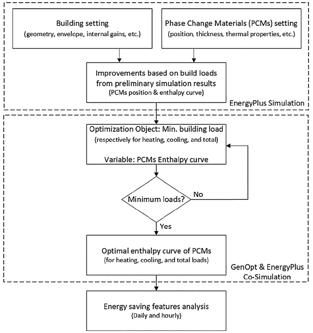
Workflow chart.
Reference building setups
This section introduces the reference building setups, including geometry, internal heat gains, and building operations schedules with thermostat settings. Detailed building envelope specifications will be provided in Section 2.3, where the integration of PCMs will also be discussed.
Building basics
To investigate the effectiveness of PCMs in cold climates, this case study focuses on Edmonton, Alberta, Canada, located in ASHRAE climate zone 7 (5000<HDD18.3°C≤7000). In this region, heating, rather than cooling, constitutes the primary energy demand for buildings.
The reference building is modelled as a one-story residential structure, drawing on design principles from Houseplans (2024), as shown in Figure 2. The internal gains are configured in accordance with the IECC 2021 standard (International Code Council, 2021). The building has a floor area of 127 m2 (11.58 m × 10.97 m) and an indoor ceiling height of 3.05 m. The roof has a pitch of 4:12, and the building is oriented directly south. There are a total of 10 windows, each measuring 1.83 m × 1.52 m, resulting in window-to-wall ratios of approximately 25% on the south and west facades, and 15% on the north and east facades. This design aims to take a reasonable amount of solar gain during the summer. For simplicity, no blinds are included in the model, and the space is treated as a single open room without internal walls. All areas, except for the attic, are considered air-conditioned, with ventilation excluded from the model. Internal heat gains account for a maximum occupancy of four people, each with a constant metabolic rate of 1.2 MET (126 W/person). Additional heat gains include a maximum of 400 W lighting and 1250 W equipment, corresponding to power densities of 3.2 and 9.9 W/m2, respectively.
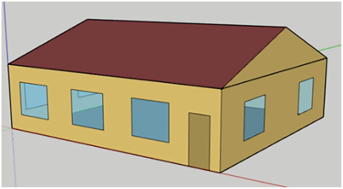
Reference building model façade.
Operation schedules and thermostats
To accurately compare and analyze the impact of different building operation schedules, two kinds of operation schedules are defined, reflecting typical activity patterns. These schedules incorporate a coupled setting of internal heat gains and thermostat controls. Figure 3 shows the internal gains (people, lighting, and equipment) intensity schedule considered in the simulation. Two operational schedules are defined: (a) normal schedule (constant); (b) night schedule (intermittent). Both schedules share the same nighttime pattern, running from 6:00 pm to 9:00 am. During this period, the building is fully occupied by four people, with reduced lighting and equipment usage after midnight, while internal heat gains peak before midnight. The primary difference between the two schedules occurs during the daytime. In the normal schedule, the building remains occupied with a lower occupancy density, and lighting and equipment usage remain relatively high. In contrast, the night schedule assumes the building is unoccupied during the day, leading to reduced lighting and equipment use. These schedules reflect typical residential patterns: the night schedule represents households where occupants leave during the day, while the normal schedule aligns with homes where half of the occupants stay at home during daytime.
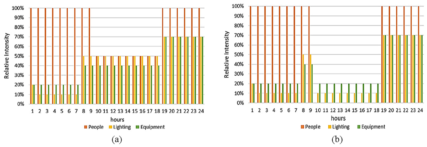
Internal gains intensity settings: (a) normal schedule (constant) and (b) night schedule (intermittent).
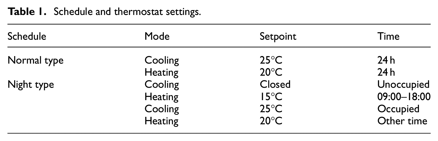
The thermostat settings in the conditioned area adjust according to occupancy status. Table 1 shows the thermostat settings for both the normal and night schedules. In the normal schedule, the room temperature is maintained between 20°C and 25°C throughout the year. This temperature range accounts for seasonal variations in clothing and ensures year-round thermal comfort. In the night schedule, the heating setpoint is lowered to 15°C during unoccupied daytime hours while cooling is turned off entirely, reflecting Alberta’s climate conditions. This approach aims to balance energy costs with thermal comfort. In extremely cold weather, the system is designed to quickly restore the room to a comfortable temperature when occupancy resumes. Cooling remains deactivated during unoccupied periods because Edmonton rarely experiences extreme heat conditions.
Schedule and thermostat settings.
Building energy simulation using optimization
EnergyPlus simulation
EnergyPlus v23.1 is used for the performance evaluation of PCM-enhanced buildings. The primary distinction between PCMs and conventional building materials lies in their phase-change properties. The physical process of PCM solidification and melting is modeled using the Conduction Finite Difference (CondFD) model, proposed by Pederson and incorporated into EnergyPlus (Pedersen, 2007), with further detailed experimental validation (Tabares-Velasco et al., 2012). This model employs an implicit finite difference scheme integrated with an enthalpy-temperature curve to precisely capture phase-change energy phenomena. Several internal nodes are established within the wallboard for the one-dimensional discretization process, enabling the calculation of temperature distribution between the indoor and outdoor environments. Given the unsteady state nature of simulation, appropriate time steps are required. Based on guidelines (Tabares-Velasco, 2012) for the use of the EnergyPlus PCM model, time steps equal to or less than 3 min are recommended. In the current work, the CondFD model with 30 time-steps per hour (2 min) is used for analyzing heating and cooling energy demands.
The choice of PCM type is also of vital importance in EnergyPlus modeling, as various PCMs with different properties are available. Some PCMs show hysteresis, also known as “subcooling,” which refers to PCMs with a lower solidifying temperature than their melting point. Although many researches focus on modeling this property (Al-Janabi and Kavgic, 2019; Zastawna-Rumin et al., 2020), for simplicity and universality, PCMs with hysteresis were excluded from this analysis. Moreover, the encapsulation method of PCMs is an important consideration in simulations. Macro-encapsulated PCMs, commonly available in the market, often contain air gaps between PCM pouches. As the CondFD method models pure heat conduction without considering convective heat transfer, it may be less accurate for Macro-encapsulated PCMs with air gaps. Some researchers have modeled this kind of PCMs without accounting for the thermal resistance introduced by air gaps (Muruganantham, 2010). However, others have calculated the equivalent total thermal resistance (“R” value) for both air and PCMs (Wijesuriya and Tabares-Velasco, 2021), which is a reasonable correction to improve the modeling accuracy. In this work, we assume isotropic properties for the PCM layer and focus on micro-encapsulated PCMs for simulation, as they offer better compatibility and accuracy with the 1-D CondFD heat transfer model in EnergyPlus.
For the demand calculation, the “idealLoadAirSystem” HVAC model in EnergyPlus is used to calculate building loads. This approach does not specify any particular type of heating or cooling equipment, making the results more generalized for reference.
GenOpt optimization
GenOpt v3.1, a Generic Optimization Program developed by Lawrence Berkeley National Laboratory, is adopted to solve the optimization problems proposed in this work. In using GenOpt as a co-simulation optimization tool, one objective function is required. The multi-objective optimizations (Carlucci et al., 2015) can also be realized by extending the standard library of GenOpt. This objective function is evaluated by an external simulation program, typically EnergyPlus, TRNSYS, or DOE-2. Since each iteration involves a complete performance simulation, the objective function is often computationally expensive. However, GenOpt is particularly well-suited to reduce the computational load in optimizing key parameters to improve energy performance.
GenOpt processes the input and output files from simulations to calculate the objective function and iteratively updates the variables to find the optimal solution that minimizes the cost (Pan et al., 2023). In this study, a template input file is created by modifying the standard EnergyPlus “idf” input file. Variables of interest, such as the enthalpy curve of PCM, are replaced with custom-defined keywords. By locating and replacing these keywords, GenOpt generates new input files for subsequent simulation runs. Prior to applying the optimization program, preliminary simulations are performed exclusively with EnergyPlus to pre-screen parameter settings. Objective functions are proposed to minimize the energy demand of the building, with a focus on cooling, heating, and overall performance respectively. The objective function is influenced by an independent continuous variable, resulting in one-dimensional optimization problems in this study. Among the optimization algorithms available in GenOpt’s library (Wetter, 2011), the Hooke Jeeves algorithm, which is a member of the Generalized Pattern Search (GPS) algorithm family, was selected for its effectiveness in solving problems with continuous variables in one or multi-dimensions. In addition, the parallel computation feature was utilized to evaluate the objective functions, maximizing computational efficiency, and reducing time costs.
Building envelope with PCMs
The PCM-enhanced building envelope is a primary focus of this study; thus, the PCMs-related settings are exclusively elaborated in this section.
Table 2 shows the material properties used for the wall, with reference PCM information provided at the bottom. The envelope specifications for the roof and windows meet the requirements of climate zone 7, and these specifications remain consistent across all simulation cases. Only the exterior wall is enhanced with PCMs, excluding the attic. The thermal performance of the basic wallboards is characterized by their respective “U” and “R” values. The insulation layer, which accounts for 91.2% of the total “R” value of the wall, provides the greatest thermal resistance and experiences the most significant temperature drop in heat transfer. Hence, in this study, installation positions of the PCM layer within the wall construction are featured by its relative position to the insulation layer.
Wall material properties used in the basic wall and additional PCM layer.
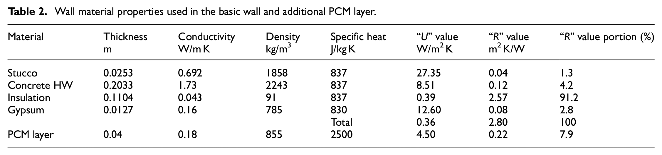
Figure 4 illustrates the construction of both the basic wall and the PCM-enhanced walls. The PCM-enhanced wall can be constructed in two configurations, depending on the placement of the PCM layer relative to the insulation. In one configuration, the PCM layer is placed inside the insulation, closer to the indoor environment. In the other, the PCM layer is positioned outside the insulation, nearer to the outdoor environment. The placement of the PCM layer significantly influences the phase change process, especially when the insulation layer blocks most of the heat flux. As a result, the PCM layer’s temperature fluctuates more significantly depending on its position relative to the insulation changes. After conducting preliminary simulations, the configuration with better performance will be selected for further co-simulation optimization.
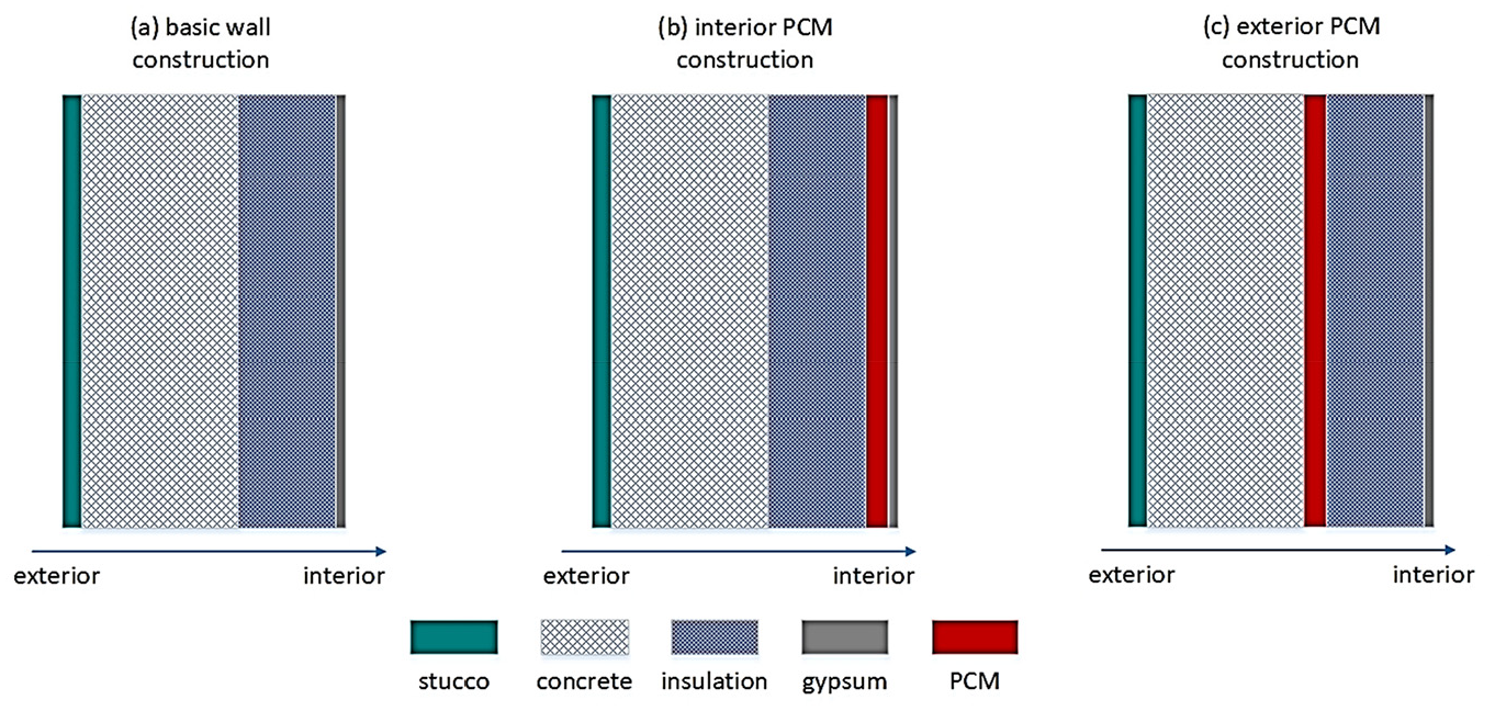
Basic wall and PCM position construction settings: (a) basic wall construction used in the benchmark cases, (b) interior PCM position construction, and (c) exterior PCM position construction.
As previously mentioned, micro-encapsulated PCM is used in this simulation for its accuracy and compatibility. The DuPont™ Energain® micro-encapsulated PCM product, from the reference experimental test (Cao et al., 2010), is selected as the prototype of the current PCM. This material features a nonlinear enthalpy-temperature relationship with a melting temperature range of approximately 6°C, centered at 21.7°C. It has a latent heat of 80 kJ/kg, a density of 855 kg/m3, and a specific heat of 2.5 kJ/kg K. The tested thermal conductivity varies between 0.14 and 0.18 W/m K. For simplicity in the simulation, the thermal conductivity is assumed to be constant at 0.18 W/m K. And a thickness of 4 cm is applied to the PCM layer in all cases, which means the heat storage density of the current PCM is equal to 2736 kJ/m2. The properties of the PCM layers are given in Table 2 as well.
Based on this micro-encapsulated PCM product, certain simplifications were made in the enthalpy curve. According to the referenced work (Tabares-Velasco, 2012), the energy-saving results are not highly sensitive to the linearization of the enthalpy curve. Thus, the nonlinear enthalpy-temperature relationship is represented linearly using 5 points, with constant gradients applied before, during, and after the phase change temperature range. As shown on the left side of Figure 5, a representation using the midpoint melting temperature
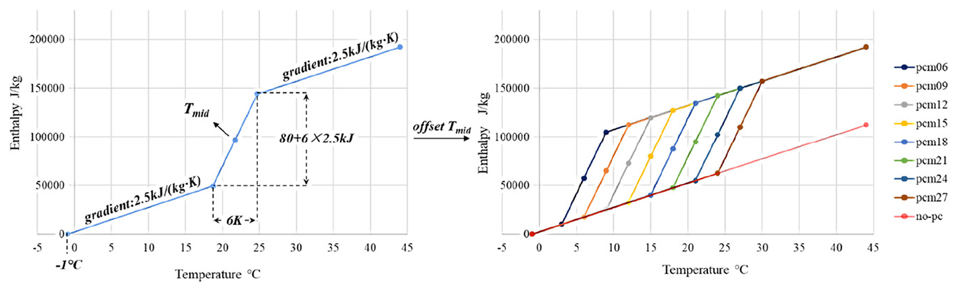
Left: five-point enthalpy curve simplification, and
Energy-saving indicators
This study focuses on the energy-saving performance to improve the selection and design of PCM-enhanced buildings. Since no specific heating or cooling systems are defined in the simulations, we evaluate building loads, namely heating and cooling energy demands, rather than the specific quantities of electricity or gas consumed. This approach offers a more general and direct assessment of energy performance. The energy-saving indicators, including the amount of energy-saving and the ratio of energy-saving, are defined as equations (1) and (2), respectively.

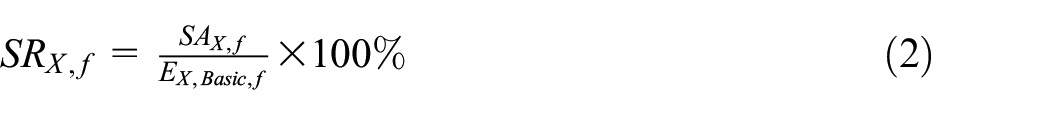
where “X” represents Heating (H), Cooling (C), or Total (T, heating plus cooling) in the energy demand simulation results. “
The indicator
One-dimensional optimization problems
In the aforementioned PCMs setup, eight kinds of PCMs with midpoint melting temperatures
Taking advantage of the co-simulation method with EnergyPlus engine and GenOpt platforms, we set up the optimization problems. Three specific single-objective, one-dimensional optimization problems are defined in Equations (3) to (5), each corresponding to a different operational schedule. The goal is to find the optimal


Problems 1, 2, and 3 are independent single-objective, one-dimensional optimization problems. The objective functions and constraints (
Results and discussion
In this part, Section 3.1 describes the results of the preliminary simulations performed solely using EnergyPlus, with manually set parameters, such as various
Preliminary simulations
The results of the preliminary EnergyPlus simulations are shown in Figure 6, which describes two indicators: the amount of energy-saving
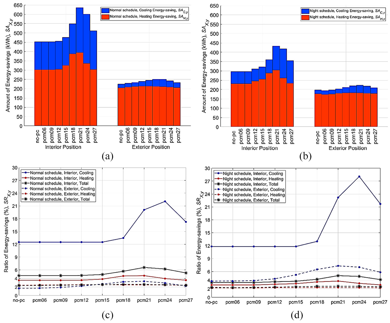
Energy-saving results of preliminary simulations: (a) amount of energy-saving
For heating energy-saving with the interior PCM installation, pcm21 showed the best performance, achieving savings of 394.5 kWh (4.7%) and 304.3 kWh (3.8%) in
For cooling performance, based on Figure 6, pcm24 with interior positioning showed the best results, achieving savings of 265.7 kWh (22.1%) and 156.6 kWh (28.1%) in
The total energy-saving
One-dimensional optimization
Optimization simulations were conducted with parameters such as the interior PCM location and the improved range of the variable
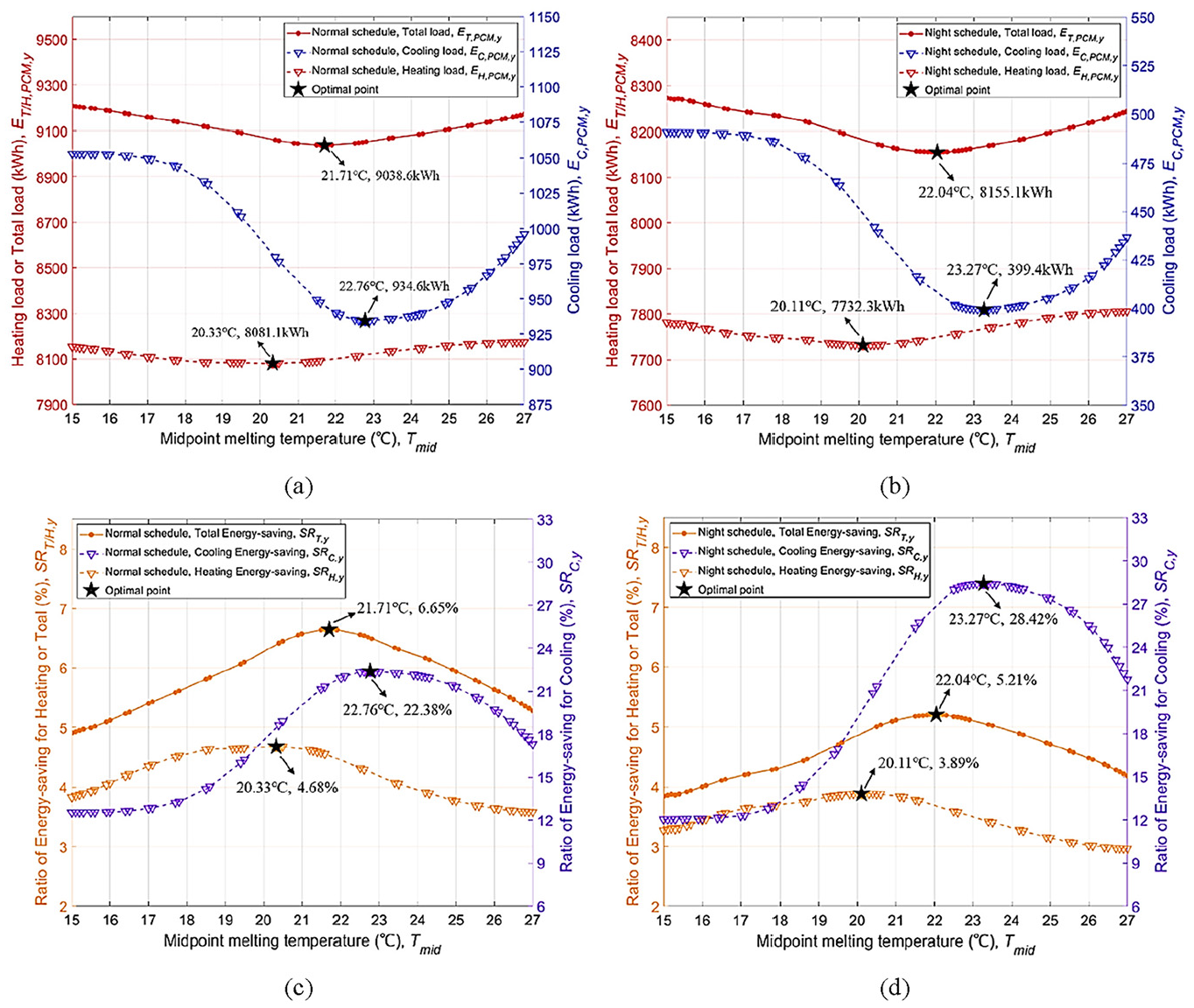
One-dimensional optimization results along with the evolution of
Focusing on the specific results, the performance profiles show similarities, with relatively close but different optimal
For cooling loads
Optimized daily energy-saving
With the optimal yearly energy-saving performance obtained, we further investigated daily performance comparisons, as shown in Figure 8. The results reflect the amount of energy saved, with heating savings
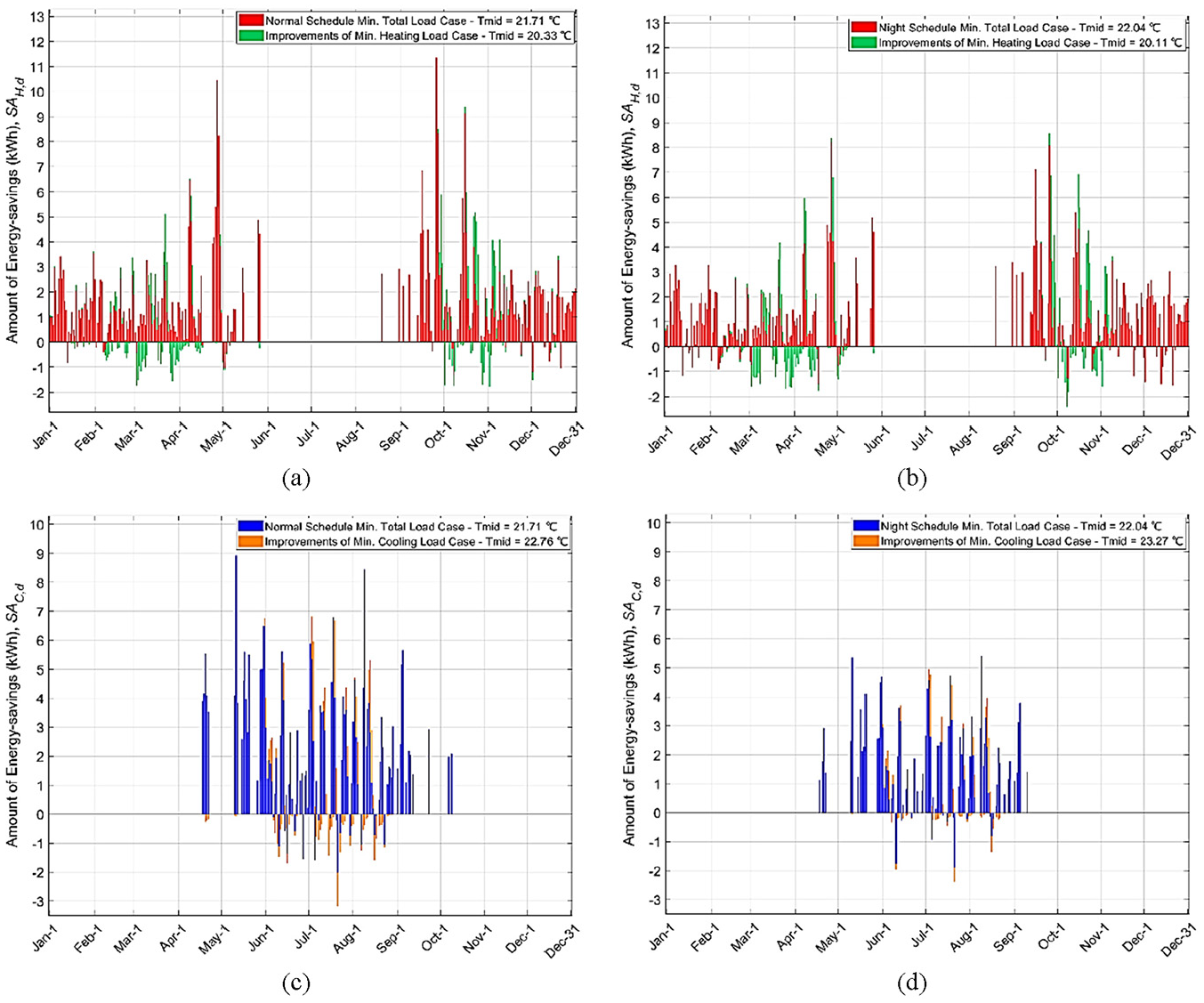
Amount of daily energy-saving of optimal PCM
The detailed daily heating and cooling energy-saving features are explained as follows. In Figure 8((a) and (b)), showing the heating results, large savings happen during the transitional seasons (near May and October). However, during the winter season, when absolute heating energy demand is high, the savings are relatively small. This indicates the importance of the phase change cycle of PCMs in practical applications, as PCMs are only activated at relatively higher outdoor temperatures; otherwise, they function as an additional layer of insulation. This is evidenced by the green bars shown in the figure, where the optimal heating-load-oriented case does not outperform the total-load-oriented case on all individual days. For instance, on certain days in March and April, no improvement of the heating-load-oriented case over the total-load-oriented case (i.e. green bars) is observed in Figure 8((a) and (b)). This demonstrates that
Hourly thermal performances of optimal PCMs
Figure 9 shows the results of building load and temperature change for typical weeks during the transition, summer, and winter seasons under normal and night schedules. For the transition season shown in Figure 9((a) and (b)), the total-load-oriented cases demonstrate optimal performance throughout the year, making them the best choice for analyzing the transition season loads. During this period, a notable reduction in peak cooling load of approximately 0.5 kW is observed during the daytime, along with the complete elimination of heating load under the normal schedule. The activation (melting) and de-activation (solidification) of the PCM create a robust cycle during the transition season. Initially, internal heat gains are efficiently stored within the PCM layer, reducing the cooling load. This stored heat is subsequently released when outdoor air temperature drops, effectively decreasing any heating load. This combination exemplifies best practices in PCM applications, resulting in the largest energy-saving ratios. Under the night schedule, the uncontrolled indoor temperature during the daytime leads to a cooling load demand that is nearly half of what is observed under the normal schedule, albeit with higher demand peaks. The use of PCM effectively mitigates these peaks, achieving an additional reduction in peak cooling load of around 1 kW.
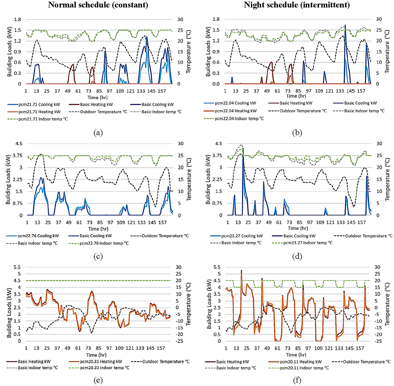
Building loads and temperature features of 168 h (1 week) of typical seasons: (a and b) heating and cooling load profile for the transition season (0512-0518) of the normal schedule and night schedule, respectively, (c and d) cooling load profile for the summer season (0719-0725) of the normal schedule and night schedule, respectively, and (e and f) heating load profile for the winter season (1219-1225) of the normal schedule and night schedule, respectively.
For the summer season, as shown in Figure 9((c) and (d)), the cooling-load-oriented optimization case is chosen for thermal feature analysis. On typical days, there are reductions in peak cooling load ranging from 25% to 40%. It’s worth noting that the heat released during the solidification process of PCM can sometimes contribute to additional cooling loads, particularly when outdoor air temperatures remain elevated at night (above 15°C in this study), as observed between 67 and 72 h on the third day. Additionally, some abnormal phenomena appear during the daytime on the third and fifth days, where the PCM layer paradoxically increases cooling loads during the day. Possible explanations can be that (1) heat released by the PCM raises the initial indoor temperature at the beginning of the day, and (2) the excessive thermal resistance that the PCM brings hinders heat transfer to outdoors when “free cooling” is available (Arkar and Medved, 2007). Under these situations, building ventilation could be highly useful in improving the performance of PCMs (Tunçbilek et al., 2020). Another finding is that, in the current case, the energy required for PCM melting primarily originates from internal gains rather than external air, even during the summer. These observations are based on the current study in Edmonton. However, in some hot regions, the PCM melting heat may come primarily from exterior sunlight or outdoor air (Ji et al., 2019).
The heating-load-oriented case is analyzed for winter PCM performance as shown in Figure 9((e) and (f)). It shows that when outdoor temperatures consistently remain below 0°C, especially for the normal schedule, it becomes challenging for the PCM to undergo phase change. As a result, the load reduction is primarily due to the thermal resistance of PCM rather than its phase change function. Notably, under the night schedule, when the thermostat is adjusted at 9 am, a portion of heat is released, reducing the heating load. However, additional energy from heating equipment is required to activate the PCMs when the room temperature is raised again at 6 pm. These two energy demands effectively cancel each other out, resulting in minimal overall savings. Although the energy-saving achieved through phase-change is modest, the PCM demonstrate excellent performance as a thermal buffer layer during winter, particularly in mitigating indoor temperature fluctuations, which is able to improve indoor thermal comfort, especially during heating equipment failures. Moreover, from the perspective of energy demand, it demonstrates significant potential to reduce the peak load and further enhance building energy flexibility (Saffari et al., 2022; Yin et al., 2024).
Recommendations for PCM application in cold climates
Alberta, a cold climate region classified as ASHRAE climate zone 7, was selected as the building site for this research. While PCMs are usually considered effective for reducing cooling loads in warmer regions, their application in cold climates can also be beneficial under specific demand conditions. Below are some recommendations for the use of PCMs in cold climates.
In cold climates, PCMs are more suitable for buildings with higher internal heat gains. Since the melting heat of PCMs primarily originates from indoor sources rather than outdoor ones in current cases, higher internal heat gains reduce the outdoor temperature needed for PCMs to function effectively, aligning well with the cold climate conditions.
PCMs are effective for buildings with unwanted temperature fluctuations. In the winters of cold climate regions, the amount of energy-saving achieved by PCMs can be limited. However, if there are unwanted temperature fluctuations, applying PCMs will not only reduce the fluctuations but also enhance thermal comfort and improve building energy flexibility.
PCMs can be a good way to reduce or even eliminate the cooling load. In cold climates, the high diurnal temperature variation during summer and transitional seasons allows lower night temperatures to facilitate the cycling of PCMs. This accelerates the solidification process at night, enabling efficient heat absorption the following day. This approach can be particularly impactful if cooling equipment, such as split air conditioners, can be entirely eliminated due to the minimal residual cooling loads, which is unlikely to happen in warmer climates.
Limitations
Some limitations exist in the current work. To start with, ventilation is not considered in the building simulation, although it has been shown to be particularly useful when combined with PCMs under intermittent operation schedules. Incorporating either forced or natural ventilation into the operation, which has been extensively researched in the literature (Arumugam et al., 2022; Barzin et al., 2015; Prabhakar et al., 2020), could significantly improve the energy-saving performance of PCM-enhanced buildings by removing unwanted indoor heat. Advanced intelligent ventilation methods used in pollution (Ren and Cao, 2019b) and thermal control (Ren and Cao, 2019a) by combining online monitoring data with fast prediction models, could also be promisingly effective in PCM-enhanced buildings. Furthermore, the heat storage density (kJ/m2) of the PCM is not explored in this study, although determining the optimal amount of PCM is vital in real engineering applications. For a given phase change material applied as a single layer in building envelopes, the heat storage density is proportional to its thickness, as both density and latent heat are normally constant properties. In the optimization of the heat storage density, energy-saving performance alone cannot serve as the sole objective. While increasing heat storage density (i.e. latent heat) usually reduces energy consumption, it must be balanced with other indicators, such as economic cost, to ensure a cost-effective solution (Baniassadi et al., 2016). Specific scenarios, including the integration of HVAC&R systems, would be necessary to accurately calculate the energy consumption and costs. Moreover, there are several other parameters given in the introduction that may have impacts on the performance of PCM-enhanced buildings, but a comprehensive optimal design may not always exist. In such cases, it is common practice to make reasonable assumptions and use constant settings for certain parameters.
Conclusions
In this study, single-objective optimization problems were formulated to identify the optimal midpoint melting temperature for minimizing annual heating, cooling, and total energy loads, respectively. The performance of PCM-enhanced building was evaluated using optimization methods under varying conditions, including operation schedules, internal heat gains, and different PCM configurations (e.g. position and melting temperature). Based on the results and discussions, recommendations for the application of PCMs in cold climates are detailed in Section 3.5. The key findings from the optimization simulations can be categorized as follows:
For the installation position, installing the PCM layer on the interior side of the insulation yields superior performance than the exterior installation. This result is logical, as the interior installation provides more direct heat transfer between the PCM layer and the indoor environment, thus reducing temperature fluctuations.
Building operation schedules and temperature settings are crucial for PCM performance. For instance, night schedules exhibited a higher energy-saving ratio for cooling compared to normal schedules, primarily due to the greater activation of PCM under intermittent cooling demand.
Midpoint melting temperature
Footnotes
Declaration of conflicting interests
The author(s) declared no potential conflicts of interest with respect to the research, authorship, and/or publication of this article.
Funding
The author(s) disclosed receipt of the following financial support for the research, authorship, and/or publication of this article: The authors gratefully acknowledge the support from the Canada First Research Excellence Fund as part of the University of Alberta’s Future Energy Systems research initiative (CFREF-2015-00001).