
Abstract
As a new type of ground transportation system, an unmanned metamorphic vehicle can naturally switch between wheeled driving and legged walking through vehicle reconstruction. Therefore, compared with traditional vehicles, unmanned metamorphic vehicles can move quickly on structural roads and have high trafficability on nonstructural roads. Furthermore, an unmanned metamorphic vehicle is applicable to interstellar detection and earthquake rescue. In this study, the topological structure of an unmanned metamorphic vehicle was designed and the reconstruction process was described. In addition, a kinematic analysis was conducted on the three stages (supporting, lifting, and standing-up) of reconfiguring the metamorphic vehicle. The kinematic and corresponding dynamic models were established based on the screw theory and the Lagrange equation. A Matlab/Simulink simulation was then carried out for the unmanned metamorphic vehicle. The simulation results describe the motion behavior of the system reconstruction, illustrating that the established kinematic and dynamic models are reasonable. Finally, the correctness of the abovementioned kinematic and dynamic models was further verified by Adams virtual prototype simulation. The above findings provide a solid foundation for future studies on stability control during the reconstruction of unmanned metamorphic vehicles.
Keywords
Introduction
With the characteristics of wheeled driving on structural roads and legged walking on nonstructural roads, a wheel-legged robot is adaptable to various types of roads. It has become the research focus for ground mobile robots.
Many scholars have conducted research on two-wheel-legged robots. For instance, Zhang et al. 1 designed the SR600 and achieved balanced standing with its two-wheeled legs through a proportion integration differentiation) controller. Boston Dynamics developed the Handle, a two-wheel-legged robot that can keep steady when turning. 2 ETH Zurich developed a two-wheel-legged robot called Ascento, which can jump. 3 Compared with the biped robot, the contact area between the two-wheel-legged robot and the ground is small, and stability is difficult to maintain. To realize standing stability control, precision of the sensor and fast calculation of the controller are required, which leads to high costs.
To improve the stability of wheel-legged robots, the research object was extended from two-wheel-legged robots to four-wheel-legged robot. In 2018, the robotics laboratory of ETH Zurich 4 successfully developed a four-wheel-legged robot named “ANYMal,” which can not only drive on four wheels but also walk on four legs. Ni 5 introduced the tandem slow active suspension system into the four-wheel-legged robot, which improved the smooth motion of the robot.
The wheels of the two-wheel-legged robot and four-wheel-legged robot mentioned above are installed at the end of the leg that cannot be folded. The whole mechanism occupies a large space because there is no deformation between the wheels and legs. Meanwhile, the legs that cannot be folded increases the center of mass of the robot, resulting in poor stability when driving at high speed. For this reason, the metamorphic mechanism can be introduced into wheel-legged robots, and a switch between wheels and legs can be realized through reconstruction of the robot. A metamorphic mechanism refers to a mechanism that alters its topological structure via changes in the number of effective member bars, the type of kinematic pairs or geometric relationship, as well as changes to its degree of freedom during continuous operation. As a new type of mechanism proposed by Dai in 1998, 6,7 a metamorphic mechanism features variable function and topological characteristics in multiple working stages. 8
Zhan et al. 9 applied the metamorphic mechanism to the wheel-legged exploration vehicle. Through the spherical six-bar metamorphic mechanism, switching between various movement modes of the exploration vehicle can be realized to adapt to dangerous and complex environments. According to the working requirements of the mechanism, Li et al. 10 designed a conceptual model of lunar exploration vehicle with metamorphic function, which has a foldable structure and can change the diameter of the wheel according to the driving road conditions to pass obstacles of different sizes. Ding et al. 11,12 designed a variable structure wheel-legged rover that changed its traveling mode by changing the configuration of the mechanism during traveling, thus, it could be used for Mars detection. Oh et al. 13 and Lim et al., 14 from the Korea Institute of Science and Technology (KAIST), improved the knee joint of Hubo, a biped robot, by adding a rolling wheel to the knee joint. Through this reconstruction, the robot can drive on all four wheels, which consist of knee rolling wheels and bipedal rolling wheels. This innovative wheel-legged transformation can not only realize bipedal walking but also realize stable four-wheeled driving.
The wheel-legged robot with the aforementioned metamorphism was locally reconstructed during wheel-legged switching, that is, the shape of the robot changed a little before and after the reconstruction, but there was little change in the position of the center of mass. The unmanned metamorphic vehicle designed in this article is a new type of deformable wheel-legged robot that can realize global reconstruction by combining a two-legged robot with an electric vehicle through a metamorphic mechanism. It can realize the reconstruction between the automobile state and the biped humanoid state through a wheel-legged switch, and the shape changes significantly with the reconstruction; thus, it has the characteristic of global reconstruction, which can be not only used in attack, reconnaissance, patrol, transportation, and other military fields but also widely used in earthquake relief, counterterrorism, explosion protection, detection of interplanetary, and other civilian fields.
To realize the global reconstruction in a relatively short time, the reconstruction must be rapid and stable. Ultimately, the robot should not be prone to toppling over during rapid reconstruction. Considering the above points, it is necessary to conduct an exploratory study on the kinetic behavior of this type of vehicle in the process of rapid global reconstruction. Based on the structure of the metamorphic vehicle designed in this article, a configuration analysis of each state during the reconstruction process is carried out. On this basis, the kinematics model of the reconstruction process of the unmanned metamorphic vehicle was established by using the screw theory, and the dynamics model was established by using the Lagrange equation. Finally, through simulations and calculations, the kinematic characteristics of the system reconstruction process are accurately described, and the rationality of the system model is proved.
Topological structure and reconstruction planning of metamorphic vehicles
The structural design of an unmanned metamorphic vehicle must not only meet the requirements of wheeled driving in the car state and legged walking in the humanoid state but should also consider the requirements of structural and morphological changes during reconstruction on space and reconstruction interference. Therefore, in the car state, the power system adopted a four-wheeled independent drive based on electric wheels, and the battery was installed in the middle and rear parts of the vehicle to obtain a reasonable front-to-back axle load ratio. To facilitate the reconstruction of the vehicle, a MacPherson suspension with compact structure that occupies a small space was used as the front and rear suspension, the four-wheeled steering by wire that abandons the steering mechanical system served as the steering system, and hydraulic brakes were used as the braking system. A folding two-legged walking series mechanism was designed and installed in the middle of the vehicle to ensure that the vertical line of the centroid passed through the point at which the series mechanism was installed when the vehicle was in the humanoid state. In the car state, the thighs and calves of the series mechanism were folded to reduce the volume, without touching the road surface. In the humanoid state, driven by the joint motors, the folding legs were opened and extended, becoming upright legs supporting the vehicle to allow it to stand up. The front and rear bodies of the vehicle were connected by a lifting bar, where one end was connected to the position of the centroid of the front body, and the other end was connected to the lifting motor of the rear body. When the car state was reconstructed into a humanoid state, the lifting motor rotated to lift the front body with the lifting bar, which transformed the front body of the vehicle in the car state into the upper part in the humanoid state. In addition, an automatic locking control mechanism was placed between the front and rear bodies, and the mechanism was locked in the car state to ensure that the front and rear bodies formed a unified rigid body and that the mechanism would be unlocked upon reconstruction. Figure 1 shows the topological structure of the unmanned metamorphic vehicle.

Diagram of an unmanned metamorphic vehicle. (a) Side view, (b) top view, and (c) front view.
The reconstruction of the unmanned metamorphic vehicle includes the forward reconstruction from the car state to humanoid state as well as the reverse reconstruction from the humanoid state to car state. Since the two processes are reciprocal and have similar motion behaviors, only the forward reconstruction from the car state to humanoid state was explored in this study. The for-ward reconstruction was divided into three stages, with the configuration of the initial car state shown in Figure 2(a). The first stage was characterized by supporting, where the supporting points of the vehicle were expanded, thereby laying a foundation for stable lifting in the follow-up stage. First, the legs at the rear of the vehicle metamorphosed, with the thighs and feet rotating counterclockwise and the calves rotating clockwise. With the insteps maintained horizontal during the movement, the thighs, calves, and feet moved coordinately until the feet touched the ground, which marked the end of the supporting stage, the configuration of which is shown in Figure 2(b), that is, the supporting state. In the second stage, known as the lifting stage, the front body was lifted. During this stage, the lifting mechanism installed at the rear of the vehicle lifted the front body of the vehicle by rotating clockwise. The lifting speed should not be too fast, and the beginning and end parts should be maintained at the same level. Figure 2(c) shows the configuration of the lifting stage, that is, the lifting state. In the third stage, driven by the joint motors, the unmanned metamorphic vehicle stood up. The ankle joint motor drove the calves to rotate clockwise, and the knee joint motor drove the thighs to rotate counterclockwise so that the unmanned metamorphic vehicle could stand up. The hip joint motor kept the rear body horizontal during the lifting process, thereby realizing the metamorphosis of the vehicle from the car state into the humanoid state. Once the third stage ended, the vehicle entered the humanoid state, as shown in Figure 2(d).

Topological graphs of an unmanned metamorphic vehicle in various configurations. (a) Car state, (b) supporting state, (c) lifting state, and (d) humanoid state.
In the above four configurations, supporting state and lifting state are the morphology displayed in the process of the reconstruction. The centroid position changes greatly and the speed is high during the reconstruction process of the unmanned metamorphic vehicle, that resulting in overturning easily, so the transitory states (as Figure 2(b) and (c)) are designed to ensure the stability of the reconstruction process of the unmanned metamorphic vehicle. The car state (as Figure 2(a)) and the humanoid state (as Figure 2(d)) are the two configurations with driving or walking function of the four states. For example, in the military investigation, to reach the observation position quickly, the unmanned metamorphic vehicle will drive fast on the structural road as four-wheel electric vehicle (as Figure 2(a)), and the lower location of centroid can ensure the stability when high-speed driving. When encountering nonstructural road surface (steps, gullies, etc.), unmanned metamorphic vehicle will reconstruct into humanoid state (as Figure 2(d)) for striding. In addition, when high obstacles affect the detection effect of unmanned metamorphic vehicle, it can also reconstruct into humanoid state to improve the detection range of vision.
Kinematic modeling during reconstruction of metamorphic vehicle
The screw theory is widely used in robotics research because of its advantages, such as clear geometric meaning, less coordinate system to be established, and avoiding singularity in calculation. In this article, the kinematics model of reconstruction of an unmanned metamorphic vehicle was established based on screw theory.
In the reconstruction motion of the unmanned metamorphic vehicle, the motion of the left part and right part is exactly the same, and thus the three-dimensional motion of the vehicle can be simplified to the motion in the sagittal plane during the forward kinematics modeling. As shown in Figure 3, when the unmanned metamorphic vehicle is in the car state, the rotation center of the hip joint is taken as the origin of the basic coordinate system S. The X axis of the S system points to the straightforward direction of the vehicle, the Z axis is vertically upward, according to the right-hand grip rule, and the Y axis is perpendicular to the paper surface outward. The projection point of the ankle joint rotation center on the sole of the foot is taken as the origin of the tool coordinate system T, and the direction of the coordinate axis of system T is consistent with that of system S. When the unmanned metamorphic vehicle is in the supporting state, the projection point of the rotation center of the ankle joint on the sole of the foot is taken as the origin of the basic coordinate system S′, and the direction of the coordinate axis of S′ is the same as that of S. Meanwhile, the centroid of the front body is taken as the origin of the tool coordinate system T′, and the direction of the coordinate axis of system T′ is the same as that of S′.

Coordinate systems of an unmanned metamorphic vehicle.
According to the screw theory, the supporting stage was modeled firstly. In the car state, the homogeneous coordinate of the origin of system T in system S is

where
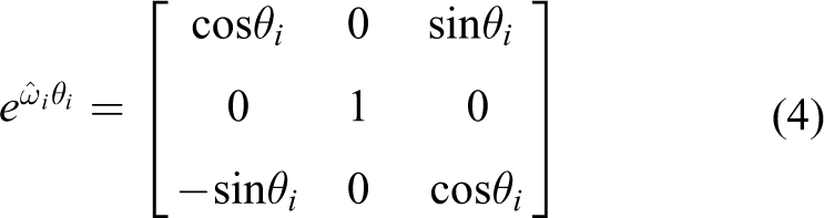
Since joints 1–4 (corresponding to the hip joint, knee joint, ankle joint, and lifting joint, respectively) are revolute joints, the rotation direction of the rotation axis

Its skew-symmetric matrix is

Joint i (i = 1–4) rotates by an angle
Then we take any point

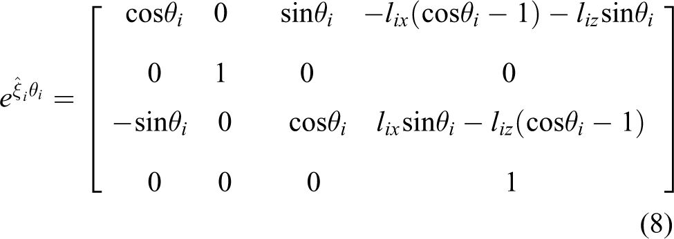
can be expressed as follows

The exponential of twist

Then, the exponential of each joint’s twist
When the unmanned metamorphic vehicle is in the supporting stage, the ankle, knee, and hip joints are in motion, while the lifting joints remain still. Therefore, the forward kinematics expression can be obtained by the orderly superposition of the screw motion of each joint

Similarly, kinematics modeling can be carried out for the lifting stage and the standing-up stage, as shown in Figure 4. The base coordinate system and the tool coordinate system are reselected as S′ and T′, respectively, where the homogeneous coordinate of the origin of T′ in S′ is

where
Different from the supporting stage, when the unmanned metamorphic vehicle is lifting, the ankle joint, knee joint, and hip joint (joints 1, 2, and 3) remain motionless, and only the lifting joint (joint 4) moves. Therefore, the forward kinematics expression of the lifting stage is as follows

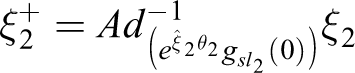
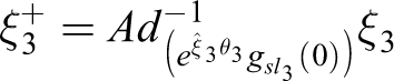
When the metamorphic vehicle is in the standing-up stage, the lifting joint (joint 4) remains stationary, and the ankle joint, knee joint, and hip joint (joints 1, 2, and 3) move. Therefore, the forward kinematics expression of the standing-up stage is as follows

Based on the reconstructed forward kinematics model of the unmanned metamorphic vehicle, the instantaneous centroid position of each component can be calculated. The homogeneous coordinate of the initial configuration in the base coordinate system S is
centroid of foot

centroid of shank

centroid of thigh

centroid of rear frame

centroid of front body

Dynamic modeling during reconstruction of metamorphic vehicle
The Lagrangian dynamic equation of the reconstruction process of the unmanned metamorphic vehicle is established as follows

where
Because the dynamic calculation methods for the supporting stage, lifting stage, and standing-up stage are the same, this article only lists the dynamic modeling process of the supporting stage. For the supporting stage, formula (18) can be rewritten as follows

where
When the unmanned metamorphic vehicle is in the initial state of the supporting stage, the body coordinate system Li
is established at the center of mass of component i (i = 1–3), and the X axis direction is about the principal axis direction of component i while the Y axis direction is perpendicular to the paper face. The Z axis direction can be determined according to the right-hand grip rule. Therefore, the inertia matrix

where
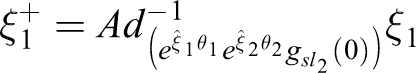
According to the above kinematic modeling, the instantaneous configuration of the body coordinate system

Let

where
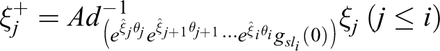
is the instantaneous twist of j-th joint relative to the body coordinate system
Then, the body manipulator Jacobian relative to the body coordinate system of the thigh can be expressed as

where
The body manipulator Jacobian relative to the body coordinate system of the shank can be expressed as

where
The body manipulator Jacobian relative to the body coordinate system of the foot can be expressed as

where


To simplify the model, the thigh, shank, foot, and other components are regarded as homogeneous slender bars, and the inertia tensor of each component


Then, the generalized inertia matrix

According to equation (20), the inertia matrix


Let hi be the height of the centroid of the component i (i = 1–3) members. Then, the total potential energy of system V is

Formula (31) is used to derive the generalized coordinates of each joint. Combining this with formulas (19), (20), and (30), the driving torque
Simulation
The physical parameters of the components of the unmanned metamorphic vehicle are shown in Table 1.
Parameters of metamorphic vehicle.

Motion characteristics of joint motor
According to the three stages of the metamorphic process described above and the positions of the joints at the beginning and end of each stage, the simulation time of each stage was set and the rotation angle of each joint at each stage was determined, as shown in Table 2.
Simulation time and rotational angle of each joint.

Once the planning of the reconstruction process was completed, to make the components rotate smoothly driven by the joint motor to reduce the impact, it was necessary joint motors. To ensure the smoothness of the joint motor drive, there should be no impact during the start–stop phase, the angular velocity of the joint motor should be stably controlled, the angular acceleration should vary steadily and constantly during the process of acceleration and deceleration, and the flexible impact of the motor caused by sudden changes in acceleration should be avoided. In this study, the motion characteristics of the joint motors were designed based on the fitted quintic polynomial.
The angular displacement S and the time t of the joint motor satisfy the following equation

Suppose that the joint motor rotates by an angle of
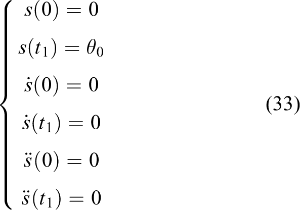
where s is the angular displacement of the motor,

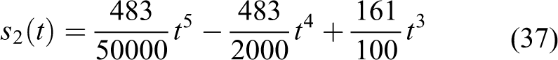
By solving the above equation, the coefficients of polynomials were obtained

and the designed motion characteristics of the motor expressed as follows

Kinematic and dynamic simulation
Owing to limitations governing the length of this article, the kinematic simulation is illustrated using only the standing-up process as the case study. According to equation (35) and the planned movement time and joint rotational angle during the standing-up stage, the motion of the motor at each joint of the folding legs is expressed as follows
Hip joint

Knee joint
Ankle joint

Figure 4 shows the curve of rotation angle of each joint under the action of the motor. During the standing-up process, as driven by the hip joint motor, the entire vehicle was rotated from 10° to 90°, the thighs were rotated from 19° to 180° under the driving of the knee joint motor, and the calves rotated from 99° to 180° driven by the ankle joint motor. The rotational angular velocity of the hip joint, knee joint, and ankle joint changed nonlinearly at a nonequal speed. The joint motors were in a phase of enhanced acceleration from 14 s to 16.1 s, which was then reduced from 16.1 s to 19 s, after which the motors were in the phase of increased deceleration from 19 s to 21.9 s and then reduced deceleration from 21.9 s to 24 s.

Curves of joint motions during the standing-up stage. (a) Angle of leg joints during standing-up stage, (b) angular velocity of leg joints during standing-up stage, and (c) angular acceleration of leg joints during standing-up stage.
As the metamorphic vehicle stood up, the centroid of the vehicle constantly changed with the movement of the joints of the vehicle. According to the equation used to solve the centroid in the system of particles

the variation trajectory of the vehicle’s centroid in the basic coordinate system was calculated (Figure 5). Based on the coordinates of the centroid, the variation in the vehicle’s centroid velocity and acceleration was solved, as shown in Figures 6 and 7.
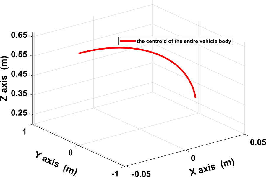
Variation of the centroid of the entire vehicle during the standing-up stage.

Variation in the centroid velocity of the entire vehicle during the standing-up stage.

Variation in the centroid acceleration of the entire vehicle during the standing-up stage.
Reconstruction stability is a very important feature in the reconstruction of an unmanned metamorphic vehicle. In the supporting stage, the support area of the metamorphic vehicle was constant and covered a relatively large area, the height of the centroid changed little, and the reconstruction was highly stable. In the lifting and standing-up stages, the height of the centroid increased significantly while the support area became smaller. Based on the reconstruction planning mentioned above and the designed motion characteristics of the joint motors, it is necessary to verify the reconstruction stability through simulation. The criterion of judging the reconstruction stability is that the system’s zero moment point (ZMP) does not exceed its support area. As the point of intersection between the ground and the extended line of the resultant force caused by the system gravity and the motion inertial force, ZMP is an important indicator for determining the motion stability of the dynamic system. The position of the ZMP of the unmanned metamorphic vehicle constantly changed with the movement of the joints of the vehicle, and its position model is expressed as follows

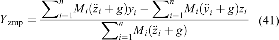
where g is the gravitational acceleration, mi
the mass of component i,
In the lifting stage, the support area of the unmanned metamorphic vehicle is a convex polygon composed of support points, such as the feet and rear wheels. The support area in the standing-up stage is a convex polygon formed by the support points of the two feet. Therefore, an approximate model of the support area of the metamorphic vehicle during reconstruction under the ground coordinate system is established as follows

According to equations (40) and (41), during the lifting and standing-up stages, the changes in the displacement of the ZMP of the unmanned metamorphic vehicle on the X and Y axes were determined, as shown in Figure 8(a) and (b). During the lifting process, the ZMP on the X axis gradually moved back from the initial position of 6.6 cm to 1.8 cm, while its displacement was always 0 on the Y axis. As the unmanned metamorphic vehicle stood up, the ZMP on the X axis gradually moved back from the initial position of 1.8 cm to −6.3 cm, while its displacement on the Y axis was always 0. As shown in Figure 8(c), the ZMP changed from −6.3 cm to 6.6 cm on the X axis of the basic coordinate system, while its change on the Y axis was substantially zero during the lifting and standing-up stages. During the reconstruction process, the ZMP was always kept within the support area, thus ensuring the stability of the reconstruction.

Variation in ZMP position during the lifting and standing-up stages. (a) Time-domain graph of displacement of ZMP during the lifting stage, (b) time-domain graph of displacement of ZMP during the standing-up stage, and (c) trajectory of the ZMP during the lifting and standing-up stages.
The equations of the motion characteristics of the joint motors at each stage were substituted into the dynamic equations of each stage to obtain the driving torque of each joint motor during the reconstruction process, as shown in Figures 9 to 11.

Variation in joint torques in the supporting stage.

Variation in joint torques in the lifting stage.

Variation in joint torques in the standing-up stage.
In the supporting stage, the folding legs were slowly unfolded, and the driving torque acting on each joint was mainly used to overcome the gravity on the components of the legs and the inertia moment of each component during the movement. As shown in Figure 9, as the foot mechanism rotated clockwise, the gravitational force arm acting on the joint gradually increased, causing the driving torque acting on the ankle joint to gradually increase from the initial value of 1.3
As shown in Figure 10, during the lifting process, the motor acting on the lifting joint lifted the front body of the vehicle, turning the supporting state into the lifting state. The driving torque of the motor was mainly used to overcome the gravitational moment on the front body and the lifting bar. With the continuous rotation of the lifting bar, the gravitational force arm acting on the lifting joint was gradually reduced, and the driving torque of the lifting motor in the counterclockwise direction gradually increased from 48.2
As shown in Figure 11, during the process in which the metamorphic vehicle stood up, the unmanned metamorphic vehicle transformed from the lifting state to the humanoid state. At this time, the primary aim of the driving torque of the motor was to overcome the gravitational moment on each component. As the thighs kept rotating, the driving torque in the counterclockwise direction of the knee motor gradually dropped from 41.6
Verification
A virtual prototype model of the unmanned metamorphic vehicle was created using Adams software. The motion characteristics of each joint motor of the unmanned metamorphic vehicle were designed into a fitted quintic polynomial. By discretizing this function, a series of data about the position and time of the rotational angle of each joint was obtained. The data were then imported into Adams to gain the spline function of the position and time, which was then used to drive the rotation of the joints, thereby achieving a motion simulation of the virtual prototype.
Figure 12 shows the simulated torque of each joint in the Adams software. Comparing Figure 12 with Figures 9 to 11, it is found that in the reconstruction of the unmanned metamorphic vehicle, the variation trend of the driving torque of each joint obtained by the dynamic model is basically consistent with that obtained by Adams, indicating the accuracy of the established dynamic model. Since the dynamic mathematical model is an ideal model, the structure of each component has been simplified, and the obtained driving torque is not completely consistent with that obtained by the Adams prototype model. However, the error is in the permissible range.

Variation in joint torques. (a) Driving torque at the hip joint during the supporting stage, (b) driving torque at the knee joint during the supporting stage, (c) driving torque at the ankle joint during the supporting stage, (d) driving torque at the lifting joint during the lifting stage, (e) driving torque at the hip joint during the standing-up stage, (f) driving torque at the knee joint during the standing-up stage, (g) driving torque at the ankle joint during the standing-up stage.
In the process of lifting and standing-up, the variation trend of position of the centroid of the unmanned metamorphic vehicle was obtained according to the Adams virtual prototype simulation (Figure 13). Moreover, this variation trend is basically the same as that gained based on the abovementioned kinematic mathematical model, thereby verifying the correctness of the kinematic model.

Trajectory of the centroid of the entire vehicle. (a) Centroid of the entire vehicle on the X axis during the lifting stage, (b) centroid of the entire vehicle on the Z axis during the lifting stage, (c) centroid of the entire vehicle on the X axis during the standing-up stage, (d) centroid of the entire vehicle on the Z axis during the standing-up stage.
According to the established virtual prototype model of the unmanned metamorphic vehicle, the simulation of ZMP changes from the supporting state to the humanoid state in different reconstruction times was carried out. Through this, we compared and verified the relationship between the rapid and stable reconstruction. As shown in equations (40) and (41), the shorter the reconstruction time, the higher the acceleration of each joint, and the greater the influence of inertia force on the stability of system reconstruction; furthermore, the ZMP curve is steeper and closer to the upper and lower boundaries of the stable region. As can be seen from Figure 8, Y ZMP remains unchanged during the reconstruction process and is always on the axis of symmetry in the support area, which has no influence on the stability of system reconstruction. Therefore, only changes in X ZMP are analyzed. Lifting times of 6 s, 8 s, and 10 s and standing times of 8 s, 10 s, and 12 s are taken as examples for analysis, as shown in Figures 14 to 16. During the simulation process, the unmanned metamorphic vehicle is always stable on the ground and no instable collapse ever occurred. Thus, the simulation results further indicate that the established mathematical model is correct.

Reconstruction with 6 s lifting time and 8 s standing time.

Reconstruction with 8 s lifting time and 10 s standing time.

Reconstruction with 10 s lifting time and 12 s standing time.
For the 6 s lifting time and 8 s standing time, although the X ZMP is still in the support domain, the stability margin (i.e. the distance between XZMP and the stability domain boundary) is very small; moreover, under the action of inertia force, its ability to resist dumping is poor. The other two reconstruction processes show better reconstruction stability. Although at the beginning and end of reconstruction their X ZMP tends to approach two boundaries of the stability regions, compared with the first reconstruction process, the stability margin is larger; additionally, due to the small acceleration, the influence of inertia force on reconstruction stability is weakened. With the further increase in reconstruction time, the X ZMP curve tends to flatten, and the antidumping ability of the system is stronger. Therefore, to realize rapid and global reconstruction of the unmanned metamorphic vehicle while ensuring stability, the 8 s lifting time and 10 s standing time were selected in this article.
Gait analysis of the humanoid state
Based on the virtual prototype model of the unmanned metamorphic vehicle established above, we also make gait planning for humanoid walking. By referring to human walking gait, the walking parameters of the biped robot (step length, foot lifting height, walking period, etc.) are set, and the displacement of the swinging foot in the plumb direction is a sinusoidal curve to reduce the impact from the ground. 15 Also, keeping the bottom plate of the foot parallel to the ground to avoid interference with the ground 16 while keep the height of the trunk unchanged (i.e. the height of the hip joint is unchanged) saves energy and reduces the amount of calculation. 17 Then the coordinates of the ankle and hip joints were solved and the coordinates of each joint of the leg were obtained by combining the coordinates of the ankle and hip joints with the screw theory. 18,19 The rotation rule was designed to ensure the smoothness of the joint motor drive according to equation (32). Finally, the rotation rule of each joint was imported into the Adams model, and the actual ZMP motion trajectory was obtained according to ZMP equations (40) and (41).
Figure 17 shows the changes in X ZMP and Y ZMP during the walking process of the unmanned metamorphic vehicle. The walking period is 1.5 s, the step length L = 0.16 m, and the foot lifting height is 0.05 m. Firstly, we lower the center of gravity and move the ZMP to the center of the left foot. At this point, although the body is supported by the left foot, it is still in the phase of two-foot support, and the support domain is the quadrilateral ACEI. Then, the right foot is lifted and takes a half step forward, entering the stage of single foot support, and the support domain is the quadrilateral ABLJ. When the right foot touches the ground, the support region becomes the convex polygon ABDFNI, and ZMP begins to move to the center of the two feet to transition to the phase of two-foot support. After that, ZMP further moves to the right foot center. Then, the left foot raises and steps forward, entering the phase of single foot support, and the support domain is the right foot, the quadrilateral KDFN. As the left foot touches the ground, the robot reenters the phase of double foot support, and the support domain is the convex polygon JKDFGH. Finally, ZMP moves to the center of the left foot. Then the right foot lifts, and the vehicle enters the single-leg support stage. The support domain is the left foot, the quadrilateral JLGH. After this action group is repeated, the biped robot can walk steadily. Figure 17 shows that the actual ZMP curve of the metamorphic vehicle is always inside the stable convex polygon region composed of two feet, which verifies the stability of the gait planning.

ZMP trajectory during humanoid walking.
Discussion and conclusion
A new type of unmanned metamorphic vehicle that can travel at high speed on structural roads and have high trafficability on nonstructural roads was proposed. The topological structure of an unmanned metamorphic vehicle was designed, and its reconstruction process from car state to humanoid state includes three stages, namely supporting, lifting, and standing-up stages. Based on screw theory and the Lagrange equation, the kinematics model and dynamics model of the global reconstruction motion were established, respectively. At the same time, based on the requirements of flexibility and compliance, the movement of each joint motor during the reconstruction process was designed. Simulation and comparison of vehicle mass center motion change, joint drive torque variation, and reconstruction stability in each reconstruction were processed by Matlab and Adams software, and the results indicate the rationality of the kinematic and dynamic models established in this study. Through simulation and comparative analysis of X ZMP changes with different reconstruction times, it was concluded that the shorter the reconstruction time, the smaller the stability threshold, and the vehicle has the advantages of rapidity and stability in the global reconstruction process. This is accomplished by reasonable structural design and three-stage reconstruction planning. In addition, the simulation of the gait planning of the unmanned metamorphic vehicle in humanoid state was also carried out.
This study only focused on analyzing the global reconstruction of an unmanned metamorphic vehicle under static parking conditions. The complex coupled motion of the global reconstructing the unmanned metamorphic vehicle from the car state to the humanoid state during dynamic driving will be explored in future investigations. This study provides a solid foundation for stability analysis and control of the rapid global reconstructions of unmanned metamorphic vehicles.
Supplemental material
Supplemental Material, sj-pdf-1-arx-10.1177_17298814221075931 - Research on the reconstruction configuration and motion behavior of unmanned metamorphic vehicle
Supplemental Material, sj-pdf-1-arx-10.1177_17298814221075931 for Research on the reconstruction configuration and motion behavior of unmanned metamorphic vehicle by Jun Liu, Pengliang Yang, Mingming Lu, Lei Sun and He Huang in International Journal of Advanced Robotic Systems
Footnotes
Declaration of conflicting interests
The author(s) declared no potential conflicts of interest with respect to the research, authorship, and/or publication of this article.
Funding
The author(s) disclosed receipt of the following financial support for the research, authorship, and/or publication of this article: This work was supported by the National Natural Science Foundation of China (Grant No. 51875148) and Major Research Development Program of Anhui Province of China (Grant No. 202104a05020040).
Supplemental material
Supplemental material for this article is available online.
References
Supplementary Material
Please find the following supplemental material available below.
For Open Access articles published under a Creative Commons License, all supplemental material carries the same license as the article it is associated with.
For non-Open Access articles published, all supplemental material carries a non-exclusive license, and permission requests for re-use of supplemental material or any part of supplemental material shall be sent directly to the copyright owner as specified in the copyright notice associated with the article.