
Abstract
To overcome the challenging problem of visual measurement and grasping of roughcasts, a visual grasping strategy for an industrial robot is designed and implemented on the basis of deep learning and a deformable template matching algorithm. The strategy helps realize the positioning recognition and grasping guidance for a metal blank cast in complex backgrounds under the interference of external light. The proposed strategy has two phases: target detection and target localization. In the target detection stage, a deep learning algorithm is used to recognize the combined features of the surface of an object for a stable recognition of the object in nonstructured environments. In the target localization stage, high-precision positioning of metal casts with an unclear contour is realized by combining the deformable template matching and LINE-MOD algorithms. The experimental results show that the system can accurately provide visual grasping guidance for robots.
Introduction
A metal cast is a common processing object in contemporary industrial production. With the popularization of industrial robots, there have been an increasing number of robotic applications combined with vision technology in industrial production. 1 The use of industrial robots for processing casts has advantages such as low labor costs, work quality improvement, and optimization of production lines. 2 –5 An industrial robot workstation based on machine vision can further automate production processes. Machine vision is another research hotspot in robot-integrated applications.
Compared with welding, handling, and other processes, industrial robots are rarely used in the processing of rough metal casts, where a lot of the work depends on manual operation. 6 Roughcasts are characterized by multiple burrs, small deformations, and indistinct contours; moreover, the production environment is poor. These factors reduce the stability and accuracy of positioning recognition of vision systems and thus increase their application cost. Under the premise of controlling the hardware cost, it remains challenging to realize a stable identification and accurate positioning of roughcasts using a vision system.
In terms of equipment, the commonly used visual guidance methods for industrial robots can be divided into two types: two-dimensional (2D) vision based on monocular cameras and three-dimensional (3D) vision based on 3D sensor. 7 Generally, a 3D vision system can provide more detailed information of the measured object; however, compared with a 2D vision system, it has drawbacks such as high cost, low image acquisition speed, and small measurement area. Therefore, a 2D vision system is still preferred for robot vision in terms of practicality.
The main problems of 2D vision in the recognition and localization of rough metal casts are as follows: There is interference in the image acquisition process: the processing environment of roughcasts is typically characterized by dust and ambient light pollution, which decreases the quality of images obtained using vision systems. In terms of the cost, this problem cannot be solved simply by adding hardware equipment. Objects are in a cluttered background: during storage and transportation, numerous scratches and/or stains occur on the surface of rough objects and the surrounding transportation equipment, leading to cluttering of the imaging background. The information contained in the cluttered background can be easily misjudged by the vision system. Objects have burrs and deformations: in the process of mass production, some cast materials undergo deformation after forming. In the case of casts in multimode production lines, the die aging and pouring process can cause burr residues and size differences on the object surface. Currently, the commonly used vision-based fine localization algorithms (such as shape-matching and PatMax) in industrial environment depend on the surface profile features of the measured object.
8,9
Such features are not evident because of the unprocessed nature of roughcasts. Some casts exhibit local reflection due to an uneven surface, which makes visual detection and localization even more difficult.
To overcome the above problems, this article proposes a localization and grasping strategy for industrial robots based on monocular vision. Combined with machine vision target detection and a localization algorithm, we demonstrate the loading and localization of a rough object by an industrial robot in the presence of external light interference and in the case where the object contour is indistinct. The proposed strategy is divided into two stages: target detection and target localization. In the target detection stage, a deep learning algorithm is used to detect the multiple local features of the object and complete the identification and coarse localization of the object in a cluttered background. In the target localization stage, we realize the precise localization of the object with an unclear contour using an improved template matching algorithm. In addition, the system can complete an automated production process with less manual intervention, ensuring the safety of the production process under the premise of controlling pollution.
The contributions of this article are summarized as follows: A new industrial robot grasping strategy for nonstructured environments is proposed. This strategy has better localization accuracy and stability than conventional methods. A new detector based on You Only Look Once (YOLOv4), which can be used in industrial areas, is proposed. This detector can realize a fast and accurate detection of similar-sized objects in nonstructured environments. Combined with a spring model structure, a deformable LINE-MOD algorithm is proposed for the precise localization of objects with unclear local edges.
The rest of this article is organized as follows: The second section presents the related work. The third section details the key points of the proposed grasping strategy for a particular type of object. The fourth section introduces the main experimental equipment, experimental environment, and experimental analysis. Finally, the article is concluded in the fifth section.
Related work
The visual localization of industrial robots has been a hotspot in industrial research. Qin et al. proposed a robot assembly strategy that combines a 2D camera and a distance sensor to locate and grasp large-volume objects; 10 they employed the strategy for a high-precision assembly of rectangular objects, the industrial robot automatic assembly of this kind of object is realized. Song et al. 11 proposed a Computer-Aided Design (CAD)-based six-degree-of-freedom pose estimation design for random bin pinking, which realize high precision robotic grasping to randomly place industrial objects. A binocular stereovision system was used for the 3D positioning of an object in ref. 12 It can realize high precision positioning and grasping of large volume metal workpiece in unstructured environment. The system has been used in industrial production and achieved good results. Le and Lin 13 proposed a 2D localization algorithm for a robot based on deep learning, which enabled an out-of-order grasping of a specific object base on the deep neural network. Literature 14 proposed a cooperative robotics pick and place system for different objects. It solving the perceptual issues posed by cluttered environments though a custom algorithm that selects a suitable picking point.
Target detection methods can be divided into conventional feature-based methods and deep learning-based methods. In the template matching method, a surface feature area of an object is selected, and a model is established, whereby the object to be identified is found in the searched image. 15 LINE-MOD 16,17 is a gradient feature-based method proposed by Hinterstoisser in 2012. The algorithm cleverly designs matching similarity criteria and uses the Steaming SIMD Extensions (SSE) parallel computing of the ×86 architecture Central Processing Unit (CPU) in the feature matching. This algorithm has a good accuracy and response speed. Since its proposal, LINE-MOD has received wide attention. Edward and Hebert 18 proposed a LINE-MOD algorithm for occlusion model optimization to solve a common occlusion problem in target detection. Some scholars have integrated the LINE-MOD model patch into a random forest to jointly estimate the position and orientation of objects. 19 Zhang et al. 20 proposed a CT-LINE-MOD algorithm combined with the cognitive template-clustering method. The above algorithms have improved the performance of the LINE-MOD algorithm from different aspects.
Deep learning has emerged as a popular machine learning method in recent years. 21 Since AlexNet, 22 which was proposed by Alex et al., won the 2012 ImageNet Challenge with an absolute advantage, deep learning has been widely studied and applied in the field of image processing. Unlike traditional template matching, target detection algorithms based on deep learning do not rely on a single feature to achieve target detection, so those methods are more capable of recognizing targets in complex environments. The object detector base on deep neural network can be divided into two categories: two-stage detection and one-stage detection. In the former case, the detection frame is defined as a “from-coarse-to-fine” process, whereas it is defined as a “one-step carry out” in the latter case. Generally, a two-stage network has better detection and positioning accuracy; however, the one-stage network is more simple and the speed is higher. 23 Representative two-stage detection networks include spatial pyramid pooling net (SPPNet), 24 fast region based convolutional neural networks (RCNN), 25 faster RCNN, 26 and feature pyramid networks (FPNs). 27 One-stage methods include YOLO, 28 single-shot multibox detector, 29 and RetinaNet. 30
In different environments, different detection objects have different characteristics. Currently, scholars began to use deep learning detector to address specific problems in different applications. In the aspect of target detection and classification, Kang and Chen 31 tried to apply the target detection algorithm to autonomous harvesting and realized the visual classification and automatic picking of mature fruits. Literature 32 proposed an automated visual inspection detector for trains exploring structural knowledge for train component detection and the method achieves pleasurable detection performance for the specified object. In addition, some scholars use different methods of image enhancement on the basis of target classification. A novel framework that applies deep learning to improve gas tungsten arc welding process monitoring and penetration detection using multisource sensing images is presented in ref. 33 The framework is capable of analyzing multiple types of optical sensing images synchronously and generative adversarial networks (pix2pix) are adopted for image denoising. Literature 34 combining generative adversarial networks and conventional approaches for image enhancement and then the welding seam detection is realized by YOLOv3 detector. Through the analysis of the above application, according to the characteristics of the target object, the improved target detector can get better detection effect than using the existing detection network directly.
Compared to the traditional target detection algorithm, deep learning localization algorithm does not have high accuracy. In addition, for the same object, many target detection networks pay more attention to the target scaling than rotation. In the industrial field, especially for the visual guidance application of industrial robots, the situation is just the opposite. Those are the common problems in the visual positioning of the blank metal casts.
To address the above problems, this article proposes a visual guidance strategy for industrial robots realized by combining the advantages of both template matching and deep learning. The strategy involves first applying the deep learning method for object recognition, followed by the template matching method for fine localization. More specifically, the deep learning method is used to separate the local features of the measured object from the cluttered background, and subsequently, the template matching algorithm is used to precisely locate the local features of the object. The proposed strategy has the advantages of good generalization performance of deep learning target detection algorithm and high positioning accuracy of template matching method. Combined with the industrial robot grasping workstation, the system realizes the high-precision and stable grasping of the blank metal casts and it solves the problems of poor robustness and low positioning accuracy in the process of grasping directly using vision guidance in a traditional robot workstation.
Grasping strategy
A rough metal cast, as shown in Figure 1, is used as the object to introduce the proposed grasping strategy. The size of the object is 209 mm × 155 mm, and the weight is 7 kg. The object is made of cast iron, and there are some burrs and stains on its surface. Because of multimode production and material characteristics, there are slight deformations on the object. The object is placed on a wooden pallet for repeated use according to certain rules, and the rotation angle around the vertical axis is no more than ±5°. The production environment is a conventional casting production workshop, which has dust and ambient light pollution due to the grinding of casts in the workshop. The robot needs to accurately position the object in sequence and complete the grasping task in a cluttered background.

Object in a cluttered background.
The template matching algorithm has advantages such as fast execution, stable matching effect, and high positioning accuracy. However, in cluttered and occluded environments, such algorithms exhibit low accuracy and recognition rate. A deep learning detector relies on a large amount of data for training. With sufficient training, the recognition rate of deep learning algorithms in cluttered environments is better than those of conventional methods; however, the accuracy is still insufficient. In this study, we combine the advantages of the two algorithms and propose a two-step positioning algorithm from coarse to fine (see Figure 2).

Grasping strategy workflow.
Rough workpiece feature positioning based on YOLOv4
The YOLO is an end-to-end target detection network proposed by Joseph in 2016. Since its introduction, the network has been favored for its high speed and accuracy. The YOLO network has been developed from v1 to v4. 35 –37 It has been developed on the basis of YOLOv4. Its network structure is in the following.
Compared with the previous YOLOv3 network, the YOLOv4 network has the following main changes:
Backbone network
The backbone network is changed from DarkNet53 to Cross Stage Partial (CSP) DarkNet53 (see Figure 3). CSPDarkNet53 uses the Res(x) Block_body structure, which can transfer more upper-layer information in the backbone network to the lower layer. Its activation function is changed from LeakyReLU to a continuously differentiable Mish function.
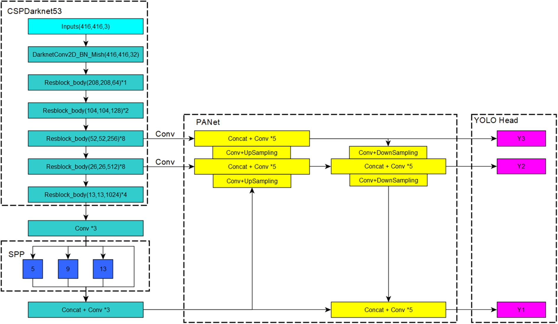
Structure of YOLOv4. YOLO: You Only Look Once.


The Mish activation function is smoother than the LeakyReLU activation function and has a comprehensive improvement in terms of training stability, average accuracy, and peak accuracy. 38
Feature enhancement part
The Spatial Pyramid Pooling Net, (SPPNet) is used, and the PAN net replaces the FPN net in YOLOv3. The SPP uses multilevel spatial bins, which have been shown to be robust to object deformations, and it can pool features extracted at variable scales. 39 For different levels of detectors, a Path Aggregation Network (PANet) net from different backbone layers was selected as a parameter aggregation method. More accurate segmentation results can be outputted by fusing the two branches.
Prediction output part
YOLOv4 still retains the output part of the three different scales in YOLOv3.
The YOLOv4 network has had additional improvements, such as the proposal of a new data enhancement method Mosaic and self-adversarial training and selection of the optimal hyperparameters when applying genetic algorithms.
To make the YOLOv4 algorithm more applicable to the classification of blank metal casts, we have made the following modifications:
A data set for industrial objects is established, including several common industrial objects: The classification problem in industrial belongs to small sample learning problem. Due to the limitation of production cost, it is difficult to collect a large number of training samples to train the deep neural network model. However, the detection performance of neural network depends on the number of training samples. 34 To ensure the target recognition effect of the detector, we enhance the target image to simulate the imaging effect under external interference in an industrial environment. The image enhance method include image rotation, shading adjustment, blur, and Gaussian noise (see Figure 4). The industrial data set can not only be used to detect the performance of the network but also be used as the pretraining.
Net structure change: As mentioned in ref, 40 the accuracy of a deep learning detector is determined by three factors: network depth, network width, and input image resolution. From the perspective of enhancing the learning ability of a CNN, Hu et al. 41 proposed a CSPDenseNet structure based on DenseNet and proved that the CSPNet structure significantly improves the DenseNet201 detector. A CSPDenseNet structure is used in the detector, and the activation function is changed to the Mish function; an Squeeze-and-Excitation (SE) module is also added (see Figure 5(c)).

Image data enhancement (from left to right are the original image of the workpiece to be grasped, rotation, shading adjustment, blur, and Gaussian noise).

(a) resblock_body in YOLOv3, (b) Res(x)Block_body in YOLOv4, and (c) DenseBlock_body added to the SE module used in this study. YOLO: You Only Look Once.
The SE module was added in YOLOv4 to enhance the performance of the detector. The objective of the SE module is to automatically obtain the importance of each feature channel through learning and then enhance the important features and suppress invalid features based on this importance. The SE module mainly includes a squeeze part and an excitation part. The first is the conversion operation based on the original net; we have

where
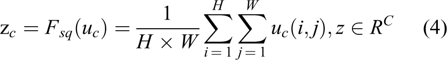
Equation (4) converts the input of
The s value is used to characterize the weight of the C feature maps in U. Finally, the weights are applied to the original features on U

The two areas of object which name feature M and feature H are selected for object detection. Considering that the size of the feature area relative to the input image is relatively fixed and the output of the detector for small target detection is removed (see Figures 6 and 8).

(a) 13 × 13 Meshing of a workpiece and local features detected by YOLOv4; the yellow area is the feature H and the blue area is the feature M and (b) 10 × 10 meshing diagram. YOLO: You Only Look Once.
The improved detector is named SE-YOLOv4 (see Figure 7). SE-YOLOv4 has a better recognition effect for the local features of the roughcasting object. The false detection rate during target detection can be further reduced using combined features.
Fine localization based on deformable Line-Mod (D-LINE-MOD)
The SE-YOLOv4 detector can well identify the object despite the influence of external interference and ambient light; however, the localization accuracy fluctuates significantly. To improve the localization and grasping accuracy of the rough object, a deformable LINE-MOD algorithm is proposed for precise localization of the roughcast on the basis of SE-YOLOv4.

Improved YOLOv4 network. YOLO: You Only Look Once.
In the process of 2D image localization, gradient information is used to generate a 2D model in the LINE-MOD algorithm. The similarity between the input image and the model is calculated using the following equation

where
Because the object surface exhibits reflection and unevenness, we may not obtain good results if the LINE-MOD algorithm is directly applied to locate the feature H of the object. Most of the improved LINE-MOD algorithms used to detect and locate objects are based on the local features of the object surface; any rigid deformation on the object is out of focus of these algorithms. Because of ambient light influence and burrs on the object surface, the change in the contour characteristics of the object is similar to nonrigid deformation during imaging. Inspired by the idea of deformable part models,
42
a deformable LINE-MOD algorithm that can realize the precise localization of objects without evident contours is proposed. The main functions of the proposed algorithm are as follows: Based on the local feature shape of the object, a gradient contour model is designed using the geometric method to avoid information loss due to external interference in the model generated directly from the image. A local feature model is generated from the feature gradient contour model. By using a spring model to identify any slight deformation of the contour, we can locate a rough metal casting with local contour deformation in the imaging due to ambient light.
Generation of feature points of gradient contour
The object contour feature points of the LINE-MOD method are selected from the gradient intensity and gradient direction; however, this method is ineffective for rough objects such as the one proposed in this article. The LINE-MOD method does not obtain enough feature points on the edge of objects, and some feature points are distributed on the object surface, which cannot provide effective information for template matching calculation (see Figure 8).

(a) Feature area H and feature points extracted using the original LINE-MOD algorithm, (b) gradient intensity image generated from the feature H area image, (c) gradient area after screening, (d) inner and outer contours of the gradient area after filtering and the extracted gradient edges, (e) feature edge feature points divided in the gradient direction, and (f) 16 sets of submodels.
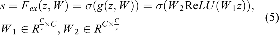
A feature points generation method based on geometric features is proposed to solve the above problems. The proposed method modifies the original LINE-MOD feature extraction method based on the gradient radial strength and gradient direction to a feature point extraction method based on contour features. The steps are as follows: The Sobel operator is used to calculate the image gradient intensity and gradient direction of the workpiece feature area
where I is the input image, G is the gradient intensity, and m_angle is the gradient direction of the image. 1. The feature points set near the contour of the feature H region are obtained using threshold filtering and region area filtering

where t is the threshold of the gradient intensity. The connected domain in GI is calculated after obtaining GI. The largest area in GI is considered the main feature area of the feature H. 2. Feature point acquisition: The main feature area includes the point with the highest gradient on the object surface. To obtain the object feature points uniformly and stably, we extract the inner and outer edges of the main feature area and calculate each point on the outer edge closest to the inner edge point. The point on the line connecting these two points with the highest gradient intensity is the main feature point on the object surface, yielding a stable and complete object edge profile (see Figure 8(d)).
Unlike the standard LINE-MOD algorithm that uses n × n convolution to filter feature points, the improved feature point extraction method can better obtain the feature points on the contour of the feature area under the influence of ambient light interference and other adverse conditions. The conventional LINE-MOD method extracts the feature points unevenly and yields invalid points under complex environments; the improved feature point extraction method has no such problems. 3. The feature points on the outline are taken as the main feature points of the feature area, and the feature points are divided in the gradient direction. The gradient feature points in the LINE-MOD algorithm are used to divide the gradient direction into eight areas. K-means clustering is used for the feature points whose gradient directions are in the same area, and all the contour feature points are divided into 16 feature point sets.
Construction of deformable models
The Histogram of Oriented Gradient (HOG) feature and filter were used in ref. 42 to obtain the position of an object; an object hypothesis specifies the location of each filter in the model in a feature pyramid, as follows

where pi specifies the level and position of the ith filter.
For the D-LINE-MOD method, the deformable model is composed of multiple submodels, and a submodel is composed of feature point sets in different directions. An annular model that reflects the shape characteristics of the H feature of the object is designed and used for the fine positioning of the objects (see Figure 9).

(a) Model for detecting human body proposed in ref. 42 (b) A ring pattern is designed to detect the feature H area.
The straight lines and shape features similar to the straight lines in the background are considered gradients in the same direction. Therefore, a single-direction feature point set cannot be used to construct a submodel. To improve the recognition rate of the object, three point sets with similar positions in the feature points set are combined into a submodel. There are intersections between adjacent submodels and 16 submodels are obtained. The relative position between each submodel is measured using a spring model and their relative positions are limited to a certain area.
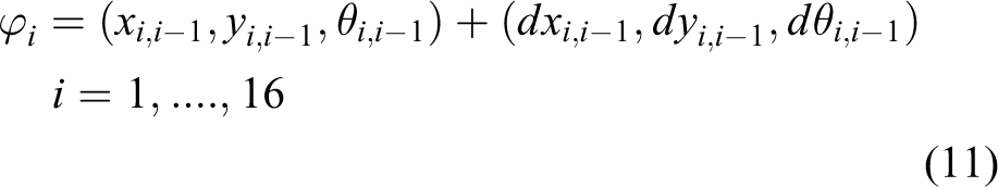
where
Similarity measurement of the deformable model
The similarity of the feature regions is obtained by weighting and summing the similarity of each submodel. With equation (7), the matching similarity score of each subtemplate can be obtained

When the positional relationship between the submodel and the adjacent model satisfies equation (11), ki is 1; otherwise it is 0. wi is the weight for each submodel, which is determined by the number of submodels that satisfy equation (11).
Calculation of matching position
Because a robot uses the relative position of the object, the relative position of the matching feature area of the object can also be calculated. In the actual positioning process, the calculation method of the position of the feature area H is as follows

where Pt is the offset of the robot grasping model position. For each submodel, Pi is its central position; then, Pm is the average of the central positions of each submodel, where n is the number of subtemplates. Pi’ is the center position after submodel matching, and Pd is the average error of all the submodels satisfying equation (11) during the matching process.
Calculation of grasping pose of industrial robot
The vision system is installed in an “eye-in-hand” manner. Zhang’s calibration method is used to complete the calibration of the relative position of the camera and the robot by imaging a fixed calibration board. For the conversion relationship between the posture measured by the vision system and the posture grasped by the robot, when the robot grasps the object

where
When the robot obtains images to the same object, we have

where

When the robot takes images of the workpieces in different positions, we have

where

(a) The pose of the robot when grasping object. (b) The pose of the robot when vision system obtains the image of the object.
Experiment
Experimental conditions and environment
An experiment was carried out in the production workshop of a foundry. The proposed grasping strategy was used for a loading robot in the robot grinding station. The loading robot is equipped with an ER50-C10 six-axis industrial robot with a 50 kg load. A Basler brand ace-3800 series industrial camera with the resolution of 3840 × 2780 is used as part of the vision system. It can provide three-channel color image. The vision system is installed at the end effector of the six-axis industrial robot (see Figure 11).

3D model and physical components of an industrial robot grasping system in different perspectives: (a) grasping robot from different perspectives and (b) 3D model of grasping robot. 3D: three-dimensional.
The figure shows that the robot grasping system is placed in an unstructured environment. The system visually detects and positions the object placed on the pallet. The acceptable grip error is ±1.5 mm.
Experimental analysis of target detection based on deep learning
We use three objects in the industrial object data set to test the SE-YOLOv4 and YOLOv4, and the detector parameters and test results are presented in Tables 1 and 2 and Figure 12. To compare detectors better, all detectors do not use pretraining model.
The initialization parameters of networks.

Test resurlt of SE-YOLOv4 and YOLOv4.

YOLO: You Only Look Once; Frames Per Second: FPS.

The detect result of SE-YOLOv4 and YOLOv4. The first line is SE-YOLOv4 and the second line is YOLOv4. (a) Test result of object 1. (b) Test result of object 2. (c) Test result of object 3. YOLO: You Only Look Once.
Recall and precision are used to evaluate the detector performance; the recall and precision is expressed as follows


TP is to predict positive class as a positive class number, FP is to predict negative classes to positive classes, and FN is to predict positive classes to negative classes.
It can be seen from Tables 1 and 2 and Figure 12 that the SE-YOLOv4 has the same recall with YOLOv4. When an object is tested individually but the precision rate is more better than YOLOv4, this proves that SE-YOLOv4 is more suitable for the detection of industrial objects. In addition, compared with YOLOv4, SE-YOLOv4 has smaller weights size and similar detection speed.
Through the experimental comparison, SE-YOLOv4 achieves better detection effect than YOLOv4 in the detection of industrial objects by improving the network structure, designing the output size, and other methods.
Experimental analysis of object in this study
A roughcasts data set comprising 400 training images and 100 test images was created for the object in this study. The images in the data set were collected from different workpieces under different lighting conditions. The data were used to train stand YOLOv4 and the improved SE-YOLOv4 detector proposed in this article; Table 3 lists the results. The accuracy means the feature area in the image is correctly detected, and error means the feature area is not detected correctly.
The roughcasts object in this article test result.

YOLO: You Only Look Once.The loss function can be used to assess the degree of inconsistency between the predicted value and the true value of the model. The lower the loss function, the better the robustness of the representative model. Figure 13 shows the changes in the loss functions of the standard YOLOv4 and SE-YOLOv4 when using the same data set for training. As shown, during the training process, the loss function of SE-YOLOv4 decreases faster than that of the standard YOLOv4. Because the network output in SE-YOLOv4 is changed from three channels to a single channel, fewer training functions were required. Therefore, the loss function of this network converges faster during the training process. Figure 14 shows the detection effect of SE-YOLOv4.

Comparison between standard YOLOv4 and SE-YOLOv4 loss functions. YOLO: You Only Look Once.

Workpiece features detected using De-YOLOv4 network. YOLO: You Only Look Once.
The above experiments show that SE-YOLOv4 can complete the detection of the two features required for the detection of the surface of the rough metal cast mentioned in this article.
De-LINE-MOD positioning experiment
We selected 80 different workpiece images obtained by the vision system under different environments and used the standard LINE-MOD algorithm and the improved De-LINE-MOD algorithm for positioning calculation for the feature area H. Because the proposed algorithm does not involve a 3D function, we only evaluated the 2D function of the algorithm.
Figures 15 and 16, respectively, show the matching results of the De-LINE-MOD algorithm and the standard LINE-MOD algorithm in the feature areas of different objects in different situations. The areas where different objects are used for matching and comparison are screened by SE-YOLOv4 positioning. To ensure the comparison effect, we set the minimum detection score to 20. As shown in Figure 15, the standard LINE-MOD algorithm has a low detection score and large fluctuations between different objects. Figure 16 shows that the LINE-MOD algorithm has only a few feature points that are correctly matched but relies on the coarse positioning calculation of SE-YOLOv4. The LINE-MOD algorithm can still successfully locate the object, which proves the effectiveness of the proposed grasping strategy. When using the De-LINE-MOD algorithm for the localization of local features, the matching score is significantly improved. Figure 14 shows that a large number of feature points are accurately matched.

2D functional similarity score comparison between standard LINE-MOD and De-LINE-MOD. 2D: two-dimensional.

De-LINE-MOD algorithm and standard LINE-MOD algorithm matching results (upper: De-LINE-MOD matching result and lower: standard LINE-MOD algorithm matching result).
To test the accuracy of the proposed strategy, a single object is placed on the ground. The object is imaged using the vision system on the robot, and the grasping posture of the object is calculated. The visual positioning results are optimized using the iterative closest point (ICP) algorithm. Table 4 lists the results.
Maximum localization error.

YOLO: You Only Look Once.The proposed De-LINE-MOD algorithm has better positioning accuracy than the standard LINE-MOD algorithm. The De-LINE-MOD algorithm optimizes the extraction of the feature points and the use of variable templates in the calculation process, making the ICP iteration process more accurate. The final positioning accuracy is also better.
The above analysis shows that even under ambient light interference, the proposed algorithm can stably identify the object features in the local area.
Grasping strategy test
The proposed grasping strategy is applied to carry out continuous production testing on an industrial site. To meet the production cycle of the post-production process of the production line, the robot adjusts the running speed such that an object is grasped every 14 s. The loading process includes the vision system image acquisition, robot grasping pose calculation, and robot operating track running time. The overall workstation can ensure that the output per hour is no less than 200 pieces.
Conclusions
In this study, we focused on an industrial robot vision positioning system for rough metals in an industrial environment and developed a novel robot vision grasping guidance strategy. The proposed strategy could achieve stable grasping of roughcastings with burrs on the surface and excessive and inconspicuous edges in unstructured environments. The proposed positioning and grasping strategy can be divided into two stages: target detection and target localization. In the target detection stage, the feature-enhanced YOLOv4 deep learning network is used to complete the identification and coarse localization of objects in a cluttered background; in the target positioning stage, combined with the elastic template theory in the deformable model, an improved LINE-MOD matching algorithm is proposed for precise positioning of the object. We also analyzed the transformation relationship between the visual coordinate system and the robot coordinate system during the grasping process of a 2D robot system. Finally, an experimental analysis was conducted, and the reliability of the proposed grasping strategy was proven by comparing it with conventional algorithms. This article provides a good solution in the form of a grasping strategy for the positioning and grasping of other similar metal casts in industrial environments.
Footnotes
Declaration of conflicting interests
The author(s) declared no potential conflicts of interest with respect to the research, authorship, and/or publication of this article.
Funding
The author(s) disclosed receipt of the following financial support for the research, authorship, and/or publication of this article: This work was supported in part by National Natural Science Foundation of China under Grant 51609033, Natural Science Foundation of Liaoning Province under Grant 20180520005, the Key Development Guidance Program of Liaoning Province of China under Grant 2019JH8/10100100, the Soft Science Research Program of Dalian City of China under Grant 2019J11CY014 and Fundamental Research Funds for the Central Universities under Grant 3132019005, 3132019311.