
Abstract
As an important research field of mobile robot, simultaneous localization and mapping technology is the core technology to realize intelligent autonomous mobile robot. Aiming at the problems of low positioning accuracy of Lidar (light detection and ranging) simultaneous localization and mapping with nonlinear and non-Gaussian noise characteristics, this article presents a mobile robot simultaneous localization and mapping method that combines Lidar and inertial measurement unit to set up a multi-sensor integrated system and uses a rank Kalman filtering to estimate the robot motion trajectory through inertial measurement unit and Lidar observations. Rank Kalman filtering is similar to the Gaussian deterministic point sampling filtering algorithm in structure, but it does not need to meet the assumptions of Gaussian distribution. It completely calculates the sampling points and the sampling points weights based on the correlation principle of rank statistics. It is suitable for nonlinear and non-Gaussian systems. With multiple experimental tests of small-scale arc trajectories, we can see that compared with the alone Lidar simultaneous localization and mapping algorithm, the new algorithm reduces the mean error of the indoor mobile robot in the X direction from 0.0928 m to 0.0451 m, with an improved accuracy rate of 46.39%, and the mean error in the Y direction from 0.0772 m to 0.0405 m, which improves the accuracy rate of 48.40%. Compared with the extended Kalman filter fusion algorithm, the new algorithm reduces the mean error of the indoor mobile robot in the X direction from 0.0597 m to 0.0451 m, with an improved accuracy rate of 24.46%, and the mean error in the Y direction from 0.0537 m to 0.0405 m, which improves the accuracy rate of 24.58%. Finally, we also tested on a large-scale rectangular trajectory, compared with the extended Kalman filter algorithm, rank Kalman filtering improves the accuracy of 23.84% and 25.26% in the X and Y directions, respectively, it is verified that the accuracy of the algorithm proposed in this article has been improved.
Introduction
Nowadays, navigation and positioning have become an indispensable part of people’s lives and also have the various applications in the field of unmanned system navigation and positioning, such as indoor autonomous sweeping robot, driverless cars, and so on. These products are constantly developing and expanding and have brought a profound impact on the technological progress of the entire society. Simultaneous localization and mapping (SLAM) is a research focus in the field of unmanned system navigation and positioning. In recent years, many investigators have conducted in-depth research on SLAM technology. 1,2 The most important significance of SLAM technology is that it not only solves the problem of autonomous positioning of mobile robot in unmanned systems but also enables mobile robot to build the environmental maps based on their own positioning in an unknown environments and then to further modify the positioning information according to the environment maps built, so that the positioning effect and the mapping effect can be improved. SLAM technology is an advantageous and substitutional module in the case of indoor mapping and outdoor Global Navigation Satellite System failure. Compared with indoor pedestrian dead reckoning positioning, Wi-Fi positioning, fingerprint library recognition positioning, and other positioning methods, 3 –5 SLAM technology has high automation and real time, which can perform mapping and positioning of indoor and outdoor environment in real time.
Smith and Cheesman 6 first proposed SLAM problem, combining both positioning and mapping around with a robot. In 1987, they presented a SLAM algorithm based on Kalman filtering (KF), but this state estimation method is only suitable for linear systems obeying Gaussian distribution of the noise. Generally speaking, the state estimation problem of nonlinear and non-Gaussian phenomena are universal, and the extended Kalman filter (EKF) is the earliest proposed state processing algorithm for nonlinear systems and Gaussian noise assumptions. Subsequently, Liu et al. proposed a central difference Kalman filter, which solved the problem of low accuracy of multi-source data fusion in SLAM applications. 7 Martinez-Cantin and Castellanos proposed an unscented Kalman filter 8 to effectively solve the problem of filter divergence caused by large nonlinear characteristics of the system.
In addition, there are quadrature Kalman filter 9 and cubature Kalman filter 10 that are used to solve the state estimation problem of nonlinear systems. In the algorithm mentioned above, the sampling points are essentially extracted from the prior distribution of the state, and then the sampling points are iterated linearly or nonlinearly. Finally, fusion is performed to obtain an accurate state estimation.
Rank Kalman filter (RKF) does not need to make Gaussian condition assumptions on the system noise in the calculation process and calculates the sampling points and the sampling points weights based on the correlation principle of rank statistics. 11,12 Because of this characteristic, it is widely used in nonlinear and non-Gaussian noise systems. Therefore, compared with other filtering algorithms, RKF algorithm has a wider application range. 13
Although Lidar can provide high-precision position and heading results, but it is easily affected by the external environment and then the positioning accuracy is greatly reduced in nonlinear and non-Gaussian noise. Compared with Lidar positioning technology, inertial navigation technology is not affected by the external environment and has the ability of independent navigation. The 100 Hz high-frequency outputs of IMU device can provide the short-term high accurate navigation parameters (position, velocity, and attitude). However, the navigation and positioning errors of IMU will gradually accumulate as time goes, so the inertial navigation needs other sensors aid to obtain high-precision navigation results. Visual information may be used in a navigation and positioning, but it has the limitation of being easily affected by the environment. In the case of violent motion and dark area, blurred images, insufficient image feature extraction, and obscure textures problems will occur.
Since the performance limitations of a single sensor, multi-sensor information fusion has become the current mainstream method of navigation and positioning. Combining several different navigation systems together can make use of multiple information sources to complement each other for the purpose of forming a multidimensional, multifunctional, and high-accuracy navigation system. At present, the mainstream integration methods are Lidar/IMU, 14,15 Lidar/Visual, 16 Visual/IMU, 17 Lidar/Visual/IMU, 18 and so on.
In this article, an RKF algorithm in the framework of loosely integrated Lidar/IMU is used to estimate the position and attitude information of the mobile robot, and it improved indoor mobile robot positioning accuracy and increased the system robustness.
SLAM problem and mathematical description
The problem of SLAM of a mobile robot can be summarized as follows: In an unknown environment, the robot calculates the current position and attitude based on the sensor data according to the needs of the position estimation during the movement process and simultaneously builds and updates the environment maps. The essence of this problem is to use the data obtained by the sensors and the known environmental information to estimate the posture of the mobile robot and describe the environmental information. Therefore, the SLAM problem can be described as shown in Figure 1.
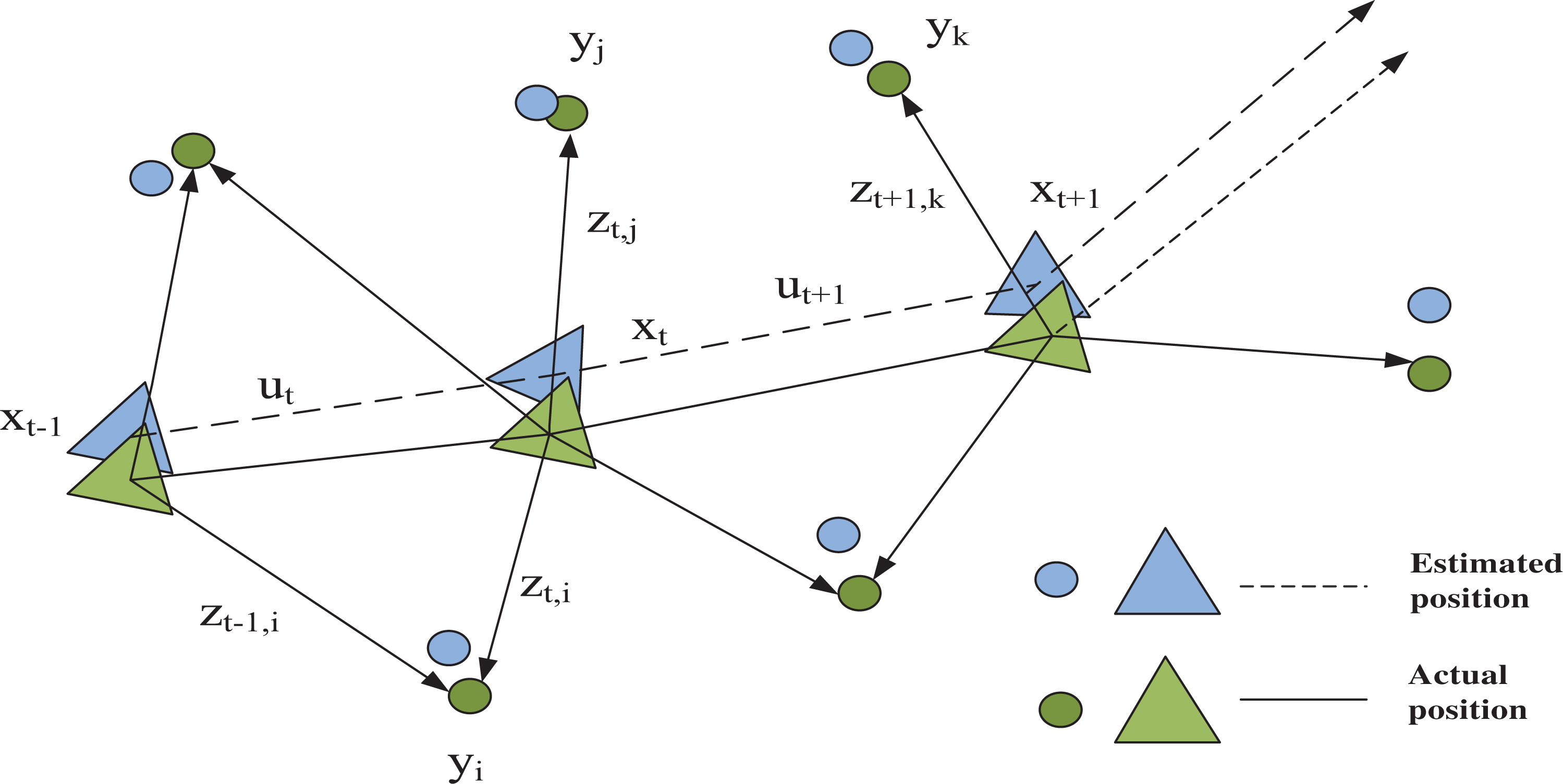
SLAM problem description. SLAM: simultaneous localization and mapping.
Generally speaking, the sensors collect data within a fixed interval, when calculating the posture of the mobile robot and updating the map, the motion of the robot in a continuous period of time can be discreated into the posture and the map at time t = 1,…K. During the two-dimensional motion, the position and orientation of the mobile robot can be represented by a three-dimensional vector

Among them,

Among them,
RKF-based multi-sensor fusion algorithm
Multi-sensor fusion algorithm
The state equation is established through the error model of strapdown inertial navigation system, and the observation equation is established through posture information calculated by the separate Lidar and IMU algorithms. Then the position, velocity, attitude, and inertial device errors of the integrated navigation system are estimated. The method is shown in Figure 2:

Structure diagram of multi-sensor fusion algorithm.
RKF design based on Lidar/IMU
RKF algorithm is used as a fusion model to process data of both IMU and Lidar to reduce the nonlinear and non-Gaussian effects of the system, and IMU in the method is used to correct the posture error caused by the alone Lidar scan matching. As a result, the final posture information is more accurate. First, a nonlinear system model is introduced as follows.
Nonlinear system model
The navigation coordinate system selected here is the geographic coordinate system of East, North, and Up. The robot error angle model of strapdown inertial navigation system 19 –21 is

Velocity error model

Position error model

where
Nonlinear system model state equation and observation equation
Selecting a 15-dimensional state vector, the state equation is as follows

where

where the measurement vector is
Calculation process of RKF
This section will introduce the RKF the calculation process.
System model analysis
Assume the following nonlinear discrete system
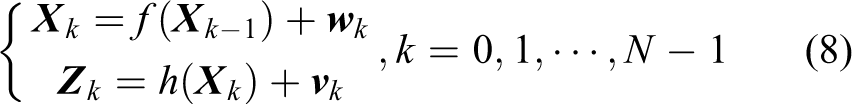
where
Principle of rank sampling
RKF algorithm calculates the sampling points and their weights according to the principle of the rank statistic correlation, therefore, there is no requirement for the system to follow the Gaussian distribution assumption. 12,13 By incorporating the idea of rank statistics into the filtering algorithm that determines the sampling type, and then the quantile is used as its sampling point to construct the sets of sampling points corresponding to the different distributions, that is,

In the formula,

RKF calculation process
The following are the specific steps of RKF algorithm:
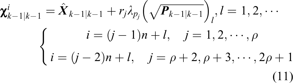
First step: time update process
According to the rank sampling mechanism shown in section “Principle of rank sampling,” the sampling point set
(2) Calculate the set of sampling points iterated through the non-linear state equation, that is,

(3) Forecast the state

(4) Calculate the covariance matrix of the prediction error

In the above formula,

Second step: measurement update process
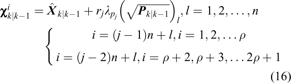
(1) Re-rank sampling to get the sampling point set
(2) Calculate the measurement value iterated through the non-linear observation equation, that is,

(3) Estimated measurement value

(4) Measurement update covariance matrix

where
(5) Measurement cross-covariance matrix

(6) Calculate the gain matrix

(7) State estimation

(8) Covariance matrix of the state estimation

Experimental analysis
Experiment environment for indoor positioning analysis
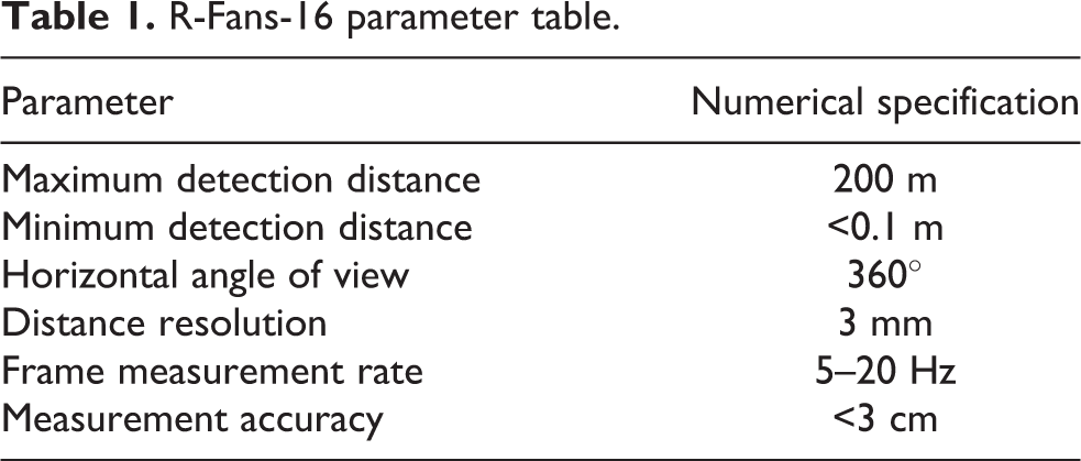
Lidar used in this experiment is R-Fans 16-line. This product is based on the time-of-flight ranging principle to obtain the point cloud data with three-dimensional scanning. The positioning principle is based on the relative motion estimation of point cloud matching, which decomposes the motion in the three-dimensional space into a three-dimensional rotation matrix R and a three-dimensional translation vector t. The performance index parameters are listed in Table 1. IMU is the model of Xsens MTI. It consists of a three-axis gyroscope, a three-axis accelerometer, and a three-axis magnetometer. The technical parameters are listed in Table 2. The experimental equipment is shown in Figure 3. The ground truth of the mobile robot in the experiment is provided by the optical space positioning system Realis Tracking System. This system can be applied to navigation trajectory of sensors, robot, or drones. It is currently the only high-precision positioning system that can meet the submillimeter level of indoor positioning. The trajectory information is provided by the corresponding TRACKER software, as shown in Figure 4. We have conducted experiments on two trajectories, one is a small-scale arc trajectory environment, and the other is a large-scale rectangular trajectory environment.
R-Fans-16 parameter table.
IMU parameter table.
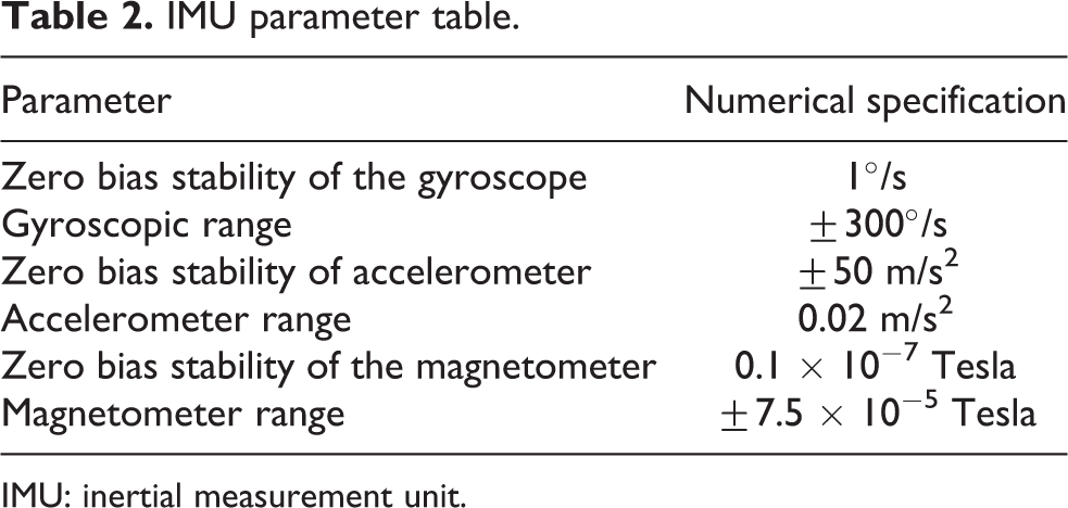
IMU: inertial measurement unit.

Mobile robot data acquisition system.
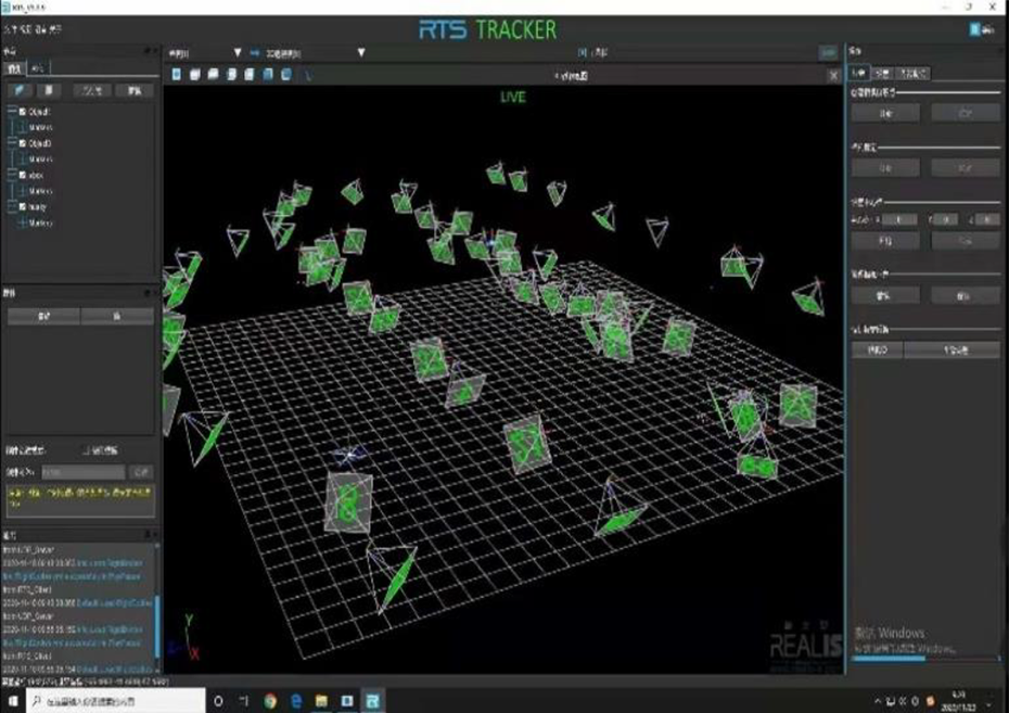
TRACKER software operation interface.
Small-scale arc trajectories environment test analysis
To verify the positioning accuracy of the algorithm, we conducted a navigation experiment of the indoor environment. The experimental site is in China BeiDou unmanned system comprehensive experimental innovation base at Shanghai Jiao Tong University, China, as shown in Figure 5. In a small-scale arc trajectory environment, the robot starts from the selected point and finally returns to the same point. The walking path is a closed loop path. Each experiment includes Lidar alone and Lidar/IMU integrated positioning tests and analyses. A KF algorithm for alone Lidar sensor, an EKF fusion algorithm for Lidar/IMU integrated system, and an RKF fusion algorithm for Lidar/IMU integrated system are used to estimate the location. The results of the positioning errors estimated by the above three algorithms are compared and analyzed. Since the alone IMU test accuracy was at the meter level for this loop path that was done by our group several years ago, 22 and is not what we discuss here at the accuracy level of the centimeter, we did not compare with the test results of IMU alone in this article.

Experimental environment.
During the positioning experiment, the trajectory is 16.28 m long, the robot starts from the starting point A (7.5057, 2.9011), at a speed not exceeding 20 cm per second walks clockwise around the polygon, finally returns to the point A. There are four turning points in the walking trajectory, namely A, B, C, D. Among them, the three turning points of A, B, and D have relatively large angles, and the turning angle of C is relatively small. The nonlinearity and non-Gaussian characteristics of the system at the turning point are more obvious, which is good for evaluating the performance of the algorithm in solving nonlinear and non-Gaussian problems. The trajectory solved by the alone Lidar algorithm, the trajectory solved by Lidar/IMU integrated system EKF fusion algorithm, and the trajectory solved by Lidar/IMU integrated system RKF fusion algorithm are compared with the ground truth. The comparison result is shown in Figure 6. The black line is the ground truth, the green line is the trajectory solved by alone Lidar algorithm, the blue line is the trajectory solved by Lidar/IMU EKF fusion algorithm, and the red line is the trajectory solved by Lidar/IMU RKF fusion algorithm. (a) is the trajectory solved by the alone Lidar algorithm and the ground truth comparison figure, (b) is the trajectory solved by Lidar/IMU integrated system EKF fusion algorithm and the ground truth comparison figure, (c) is the trajectory solved by Lidar/IMU integrated system RKF fusion algorithm and the ground truth comparison figure, and (d) is the all trajectories comparison figure.
First, the alone Lidar positioning test is analyzed. In section AB, the walking path of the robot is a straight line. During this time, due to the linear characteristics of the system, no large positioning error will occur. When it turns at the point B, C, D, and A, there is a nonlinearity and non-Gaussian characteristics of the system, which is caused by two wheels of differential rotation, and make the mobile robot vibrative (quivery). At this time, the nonlinearity and non-Gaussian characteristics of the system are enhanced, the Lidar is prone to the scan matching errors. As a result, the trajectory fluctuates greatly and trajectory drift occurs. In the whole process, the maximum error in the X direction is 0.1489 m, and the maximum error in the Y direction is 0.1456 m. With the time goes, due to the limited ability of Lidar Loop Closing function, the cumulative error is difficult to be eliminated, and it increases significantly. As can be seen from Figure 6(a), the mobile robot did not eventually return to the end point but returned to the point (7.4533, 2.9492).
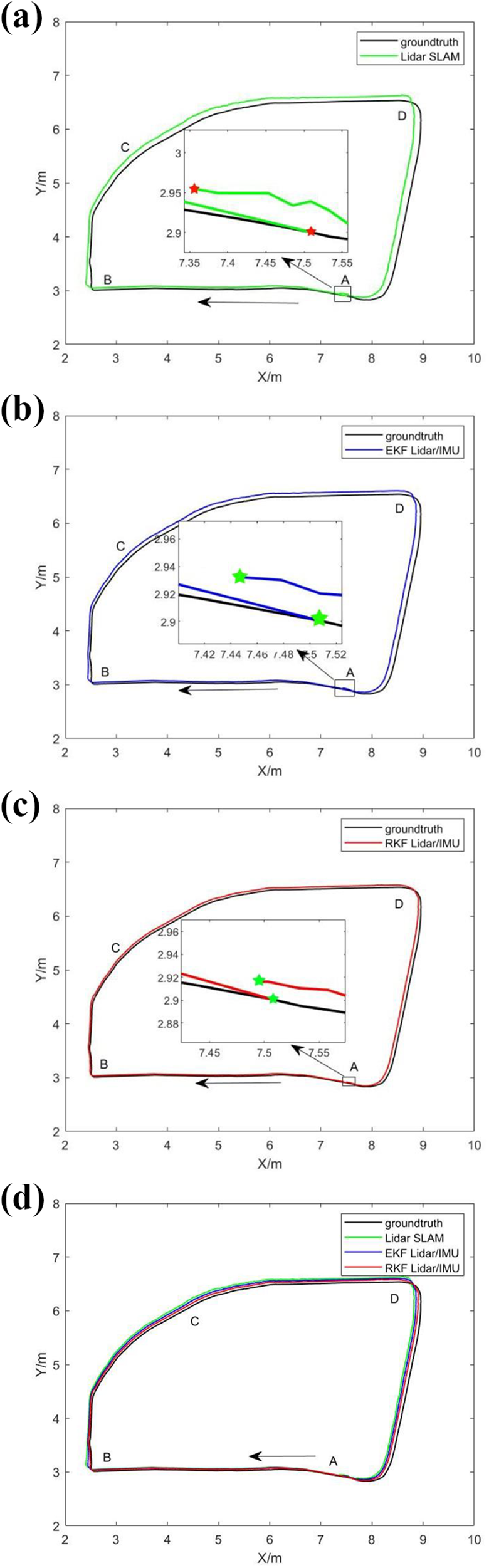
The trajectories of small-scale arc environment. (a) The trajectory solved by the alone Lidar algorithm and the ground truth comparison figure; (b) the trajectory solved by Lidar/IMU integrated system EKF fusion algorithm and the ground truth comparison figure; (c) the trajectory solved by Lidar/IMU integrated system RKF fusion algorithm and the ground truth comparison figure; (d) all trajectories comparison figure.
Second, Lidar/IMU EKF integrated system positioning test is analyzed. When it turns at B, the trajectory wave still fluctuates and there is a little trajectory drift. This is because the robustness of the EKF algorithm in processing nonlinear systems and non-Gaussian noise is not very strong, so there are certain limitations. However, compared with the alone Lidar algorithm, the trajectory solved by Lidar/IMU EKF fusion algorithm in the whole process was closer to the trajectory of ground truth.
At last, Lidar/IMU RKF integrated system positioning test is analyzed. During the whole trajectory, the positioning error of the mobile robot is very small, basically close to the ground truth. In the whole process, the maximum error in the X direction is 0.0753 m, and the maximum error in the Y direction is 0.0479 m. It can be seen RKF algorithm has a stronger ability to restrain the error divergence caused by nonlinear systems and non-Gaussian noise. Although the IMU position drift error is existing, the attitude deviation of Xsens MTi is relatively small due to its better attitude constraints. And the attitude information collected by MTi is used to compensate for the posture error caused by the alone Lidar scan matching through RKF, which can improve the positioning accuracy of the direction angle, and also improve the stability of the integrated system. In addition, by adding IMU sensing information, the cumulative errors 14,18 in the process of Lidar data processing are compensated and updated in real time, the fusion algorithm can better perform cumulative errors, it can be seen from Figure 6(c) that the last position (7.5032, 2.9110) the robot returns (the end point) to is very close to the starting point (7.4533, 2.9492). Further quantitative analysis is shown in Table 3.
Results of error statistics of three positioning methods.

Table 3 shows the error statistics in the X and Y directions with the three algorithms for indoor positioning, where STD is the standard deviation, MAX is the maximum error value, and mean is the average error. Compared with the results of the alone Lidar KF algorithm and Lidar/IMU integrated system with EKF, Lidar/IMU integrated system with RKF obtains better the results. It can be seen from Table 3 that nonlinearity and non-Gaussian properties have a greater impact on the alone Lidar positioning with KF and Lidar/IMU integrated system with EKF, but the Lidar/IMU integrated system with RKF fusion algorithm can deal with this situation very well and has a better accuracy than the alone Lidar positioning algorithm.
Through multiple experiments to further verify the positioning accuracy of the algorithm, we did five tests around the polygon and get five sets of data for analysis. The results of alone Lidar algorithm and RKF algorithm comparison are shown in Table 4, and the results of EKF algorithm and RKF algorithm comparison are shown in Table 5. As we can see, the mean value of X direction error with alone Lidar algorithm is 0.0928 m, the mean value of Y direction error is 0.0772 m, the mean value of X direction error with Lidar/IMU integrated system with EKF is 0.0597 m, and the mean value of Y direction error is 0.0537 m, while the mean value of X direction error with Lidar/IMU integrated system with RKF is 0.0451 m, and the mean value of Y direction error is 0.0405 m. As a result, compare with alone Lidar algorithm, the new algorithm improves the mean accuracy rate of 46.39% in the X direction and 48.40% in the Y direction. Compared with EKF algorithm, the new algorithm improves the mean accuracy rate of 24.46% in the X direction and 24.58% in the Y direction.
Alone Lidar algorithm and RKF algorithm comparison.

RKF: rank Kalman filtering; IMU: inertial measurement unit.
EKF algorithm and RKF algorithm comparison.
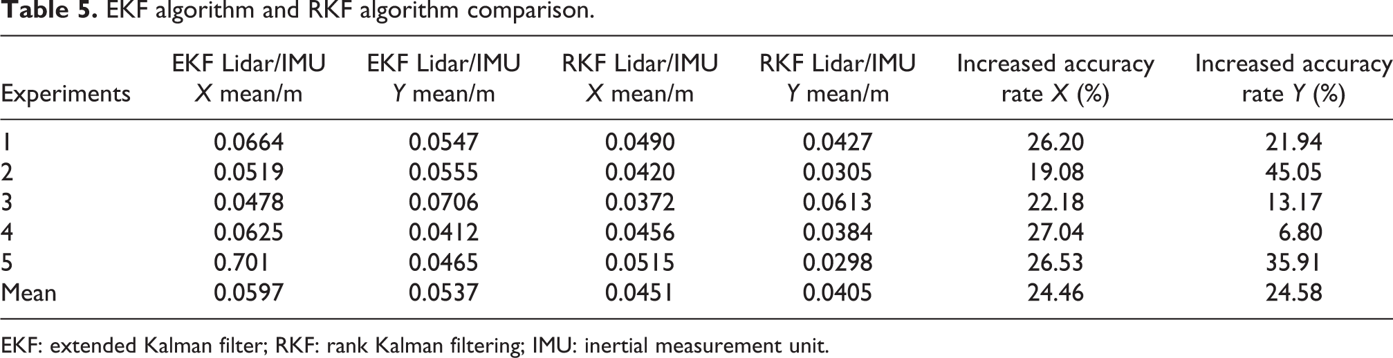
EKF: extended Kalman filter; RKF: rank Kalman filtering; IMU: inertial measurement unit.
Large-scale rectangular trajectories environment test analysis
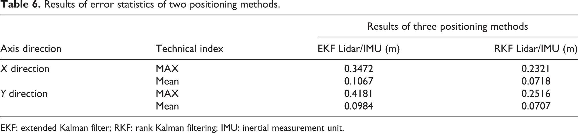
To ensure the reliability of the results, we repeated the experiment several times in a large-scale rectangular trajectory environment. The trajectory is 54.7 m long, the trajectory solved by Lidar/IMU integrated system EKF fusion algorithm and the trajectory solved by Lidar/IMU integrated system RKF fusion algorithm are compared with the ground truth. The comparison result is shown in Figure 7. The black line is the ground truth, the blue line is the trajectory solved by Lidar/IMU EKF fusion algorithm, and the red line is the trajectory solved by Lidar/IMU RKF fusion algorithm. The black solid point is the starting point, the black hollow point is the end point of the RKF algorithm, and the green hollow point is the end point of the EKF algorithm. Table 6 shows the error statistics in the X and Y directions with the two algorithms for indoor positioning. In the EKF algorithm, the maximum error in the X direction is 0.3472 m, and the maximum error in the Y direction is 0.4181 m. In the RKF algorithm, the maximum error in the X direction is 0.2321 m, and the maximum error in the Y direction is 0.2516 m.

The trajectories of large-scale rectangular environment.
Results of error statistics of two positioning methods.
EKF: extended Kalman filter; RKF: rank Kalman filtering; IMU: inertial measurement unit.
To ensure the reliability of the results, we repeated the experiment several times in a large-scale rectangular trajectory. The results of EKF algorithm and RKF algorithm comparison are shown in Table 7, the mean value of X direction error with EKF algorithm is 0.1147 m, and the mean value of Y direction error is 0.1052 m, while the mean value of X direction error with RKF algorithm is 0.0875 m, and the mean value of Y direction error is 0.0786 m.
EKF algorithm and RKF algorithm comparison.

EKF: extended Kalman filter; RKF: rank Kalman filtering; IMU: inertial measurement unit.
Conclusions
Aiming at the problems of low positioning accuracy of Lidar SLAM with nonlinear and non-Gaussian noise characteristic, this article uses Lidar and IMU integrated navigation system and proposes a fusion RKF algorithm to realize positioning estimation of the indoor mobile robot. RKF algorithm is the core of the fusion method. With its unique sampling mechanism, it can improve the positioning accuracy of the indoor mobile robot under nonlinear model and non-Gaussian noise model. Finally, multiple experimental results and analysis verify that the proposed algorithm improves the accuracy and robustness of the positioning system compared with the alone Lidar positioning algorithm. It has higher positioning accuracy, better system stability, and stronger robustness and is very important in trajectory calculation.
Footnotes
Declaration of conflicting interests
The author(s) declared no potential conflicts of interest with respect to the research, authorship, and/or publication of this article.
Funding
The author(s) disclosed receipt of the following financial support for the research, authorship, and/or publication of this article: This work is supported by the projects of the National Natural Science Foundation of China (Grant No. 41764002) and the national key technologies research and development program (No. 2016YFB0502002).