
Abstract
This article proposes a modification of hybrid A* method used for navigation of spherical mobile robots with the ability of limited partial lateral movement driven by pendulum. For pendulum-driven spherical robots with nonzero minimal turning radius, our modification helps to find a feasible and achievable path, which can be followed in line with the low time cost. Because of spherical shell shape, the robot is point contact with the ground, showing different kinematic model compared with common ground mobile robots such as differential robot and wheeled car-like robot. Therefore, this article analyzes the kinematic model of spherical robot and proposes a novel method to generate feasible and achievable paths conforming to kinematic constraints, which can be the initial value of future trajectory tracking control and further optimization. A concept of optimal robot’s minimum area for rotation is also proposed to improve search efficiency and ensure the ability of turning to any orientation by moving forward and backward in a finite number of times within limited areas.
Introduction
Spherical mobile robots based on pendulum are a particular kind driven by pendulum inside spherical shell, changing the center of gravity of the pendulum to produce eccentric moment for driving spherical shell movement. They are considered nonholonomic because of differential constraints that cannot be completely integrated, which means the robot’s configurations are not restricted to lower dimensional subspace of configuration space,
1
especially referring to kinematic constraints of orientation change, and longitudinal and lateral motion. For a nonholonomic ground robot like wheeled robot, its configuration state can be defined and described by three degrees of freedom (3DOF): x, y referring to Cartesian coordinates and yaw angle
The development of spherical mobile robots has experienced a long time. Although extra tilt movement of spherical robots reduces motion stability, because of its advantages of safety and friendly interaction with environment for all electronic components that are enclosed in the spherical shell, it is easy to satisfy amphibious scenarios like factory patrol, security guard, fire protection, and so on. In the early stage, spherical robot is a spherical shell containing a universal steering wheel designed by Ferrière and Raucent. 3 Halme et al. proposed a spherical robot with a single wheel resting on the bottom of a spherical shell. 4 Bicchi et al. proposed a sphere containing a differential driven wheeled robot to indirectly drive spherical shell motion. 5 Although designed in different ways, the main principle of spherical robot motion is to change the position of the center of gravity to produce eccentric moment. Joshi and Banavar proposed a design, where two DC motors associated with two flywheels are mounted inside the sphere. 6 Xiao et al. proposed a spherical robot driven by pendulum with two inner motors and developed a series of spherical robots named BY-X for different uses, such as land and amphibious scenarios. 7 Modeling analysis of spherical robot driven by pendulum with two motors has been decoupled by Kayacan et al. who discuss the relationship between tilt angle, lateral movement, and turning radius. 2 Roozegar also proposed a model-free reinforcement learning algorithm based on extended classifier system to navigate a spherical robot, which is an end-to-end method of both plan and control for spherical robot. 8
The purpose of navigation for a robot is to find a physically achievable collision-free path to guide the robot to the target, avoiding all the obstacles at the same time, which guarantees that the generated path can be kept in line by the specific nonholonomic robot with a specific model, considering its kinematic constraints and dynamic constraints. A lot of research have been done on car-like robots. Fox et al. proposed dynamic window approach (DWA) 9 algorithm, which samples in discrete control space. Rösmann et al. analyzed kinodynamic model of car-like robots and proposed time-band algorithm 10 and motion planning control 11 method to control robots. Kinematic model of more complicated car-like robot-like tractor with multiple trailers is analyzed by Xu 12 and Li. 13 By discussing the different kinematic models of different ground mobile robots like differential drive robot, wheeled robot, and spherical robot, the navigation methods need to be modified for adaption.
For a differential drive robot, if the left wheel and right wheel rotate at the same rate and in opposite directions, the robot would rotate its yaw direction with no translation.
14
Balkcom and Mason proposed a method for differential drive vehicles that the optimal path can be described as a series of four basic action module: forward, backward, turning left and right, and only changing position when moving forward/backward. So, the path is indeed connected by several linear segments.
15
For vehicles that have nonzero turning radius, Dubins proposed a well-known method as Dubins curves.
16
The importance of the method is that with the constraints of curvature, Dubins proved that if only considering moving forward, the minimal length of trajectory connecting initial and final poses can be described as a path specifically consisting of arcs and straight line segments, and the radius of all arcs can be defined as the same
Path planning techniques are generally classified into four groups: sampling, graph-search, interpolating, and numerical optimization. 18 The widely used methods in robotics of sampling-based plan algorithms are probabilistic roadmap method, rapidly exploring random tree (RRT), and their modifications like RRT*, 19 –22 which initially cannot guarantee feasibility for nonholonomic robots, but constraints are taken into consideration by these improved methods, hence, RRT* methods have been widely used in motion plan of manipulators and trajectory finding in structured areas. Graph-search-based planning techniques are mainly based on grids, which can be obtained simultaneously from the different kinds of sensors of robots to estimate whether they are free or occupied and robot’s own position. 23,24 To improve the search efficiency, Theta* algorithm 25 was introduced by Daniel et al. to apply an any-angle search algorithm, which can connect distant grid cell with straight lines, making obtained path smoother and more efficient. Yap et al. proposed the Block A* method 26 that utilizes a database of local distances between blocks, which contain more than eight nearest blocks, making it more efficient than A* or Theta*.
The Standford University team proposed a developed algorithm named Hybrid A* and used in its nonholonomic autonomous driving car for DAPRA Ubran Challenge,
27
estimating heuristic cost in two different ways and adding Reeds–Shepp shot path to reduce search time cost. The algorithm adds direction of motion as the fourth dimension for robot’s state space: two Cartesian coordinates x, y, orientation
Although Hybrid A* method takes nonholonomic constraints into consideration, its implement needs modification for spherical robot with different kinematic model. Since the method is based on graph search in grid maps and there is up to one explored node in one grid of selected path, the prune of potential surrounding nodes leads to the decrease of probabilistic approximate completeness, affected by the size of grid and length of node expansion, which is also relevant to search success rate because of time and storage cost of node expansion. When in narrow space, the orientation of initial/goal affects the search cost and efficiency. A concept of minimal area rotation is proposed to help improve search success rate and efficiency.
Kinematic model of spherical robot
Spherical robot
Spherical robot moves by changing the position of its pendulum inside the spherical shell. The top view and front view of spherical robot motion are shown in Figure 1. The radius of spherical shell is r and the position P of robot is vertical projection of spherical center, with orientation indicated by

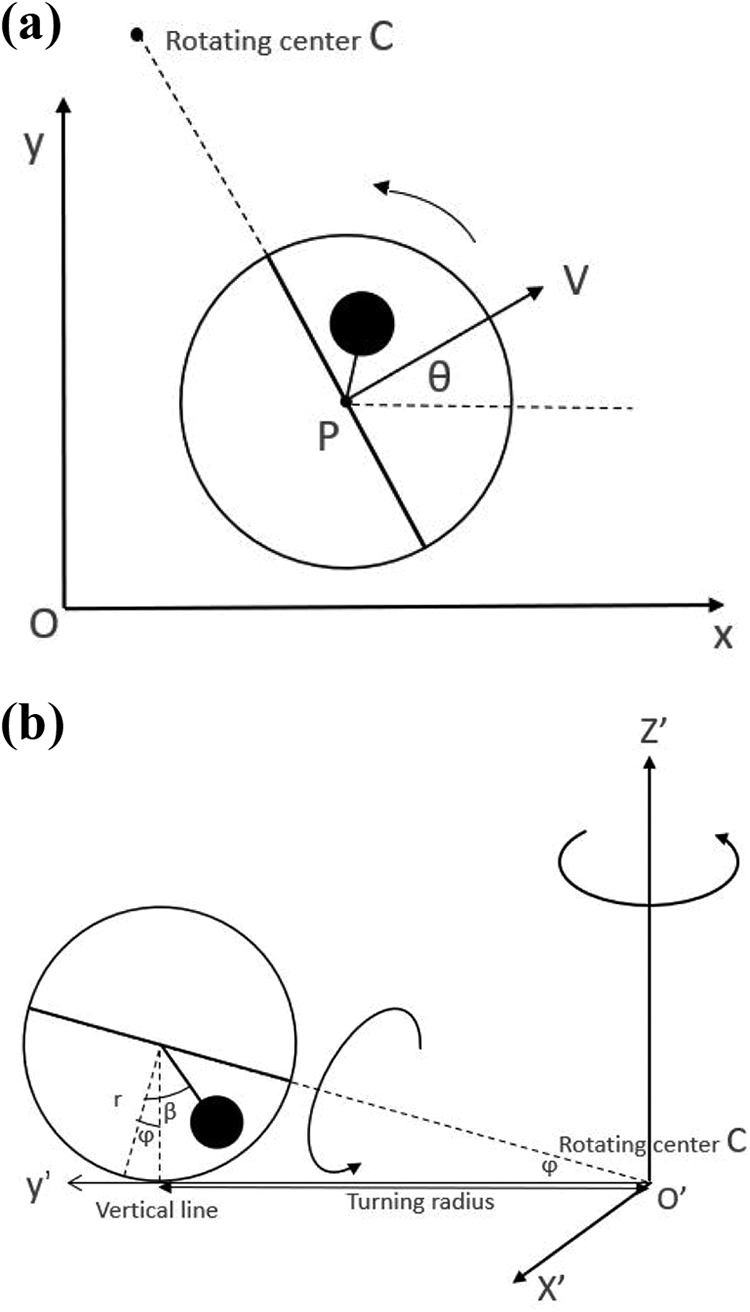
Top and front view of spherical robot, motion: turning left. (a) Top view and (b) front view.

Framework and hardware of our designed spherical robots: (a) Physical view of our enclosed robot, (b) physical view of our experiment robot, and (c) attached sensors of our experiment robot.
As shown in equation (1), the derivative of position and orientation is determined by parameters of sphere’s velocity v, orientation

With the determination of minimal turning radius, the rule of node expansion of spherical robot is also determined. Figure 3 shows a scenario of left-hand rotation: the spherical robot starts from rest and then tilts

Spherical robot rotates a circle, sets of sphere center’s poses.
Summary and comparison
Common ground mobile robots like wheeled car-like robot and differential robot show different kinematic models compared with spherical robot, as shown in Figure 4. Both of them are stable on the ground and have no lateral movement ability under normal conditions, while spherical robot is one point contact and easy to tilt caused by internal (torque of motor) or external factors (wind and uneven ground), leading to lateral movement. Differential robot’s driving wheels are driven by two separate motors with different speeds, allowing it to move and even rotate in place, which means it has a minimal zero turning radius. Wheeled car-like robot’s turning radius depends on two parameters: the steering angle

Parametric notations of wheeled robot and differential robot, where R is turning radius of wheeled robot and the velocity of differential robot is average of two wheels.
In conclusion, the kinematic model of spherical robot is more complicated than wheeled robot and differential robot because of lateral movement. And path planning for spherical robots is less complicated than monocycle robots with less constraints on control space and action space because there is no risk of overturning. For spherical robots, there are two pivotal parameters, in which traditional wheeled robots do not have tilt angle
Improved search algorithm
As discussed in the previous section, the kinematic model of spherical robots differs from wheeled robots, in which traditional Hybrid A* method is proposed for. So, modification is needed for adaption in spherical mobile robots. Moreover, hybrid A* method sacrifices complete theoretical guarantees of search completeness for the sake of real-time requirement of search and the dispersion of the continuous state space. There are several scenarios that may cause the failure of hybrid A* search: (1) search time is too long to guarantee real-time performance; (2) memory overflow caused by too many expanded nodes; and (3) search process ends before reaching the final state because of the empty of node’s open list. The first two reasons are caused by the parameter sets and the hardware situation (scenario 1 is more often), which can be improved by adjusting parameters, such as increasing the distance of expansion nodes, modifying the weight of heuristic value, and so on. The third reason mostly appeared during path search in narrow space, when narrow space is near the goal pose in particular case, the scenario becomes similar to issues of parallel parking of wheeled car-like robots. And if the basic grid size of map becomes smaller and node expansion distance is set shorter, the whole time and storage cost will increase correspondingly. The unique shape of spherical robots not only helps to decrease calculating costs when it comes to collision detection but also shows great potential to change orientation and find a feasible path in narrow space, avoiding getting stuck in the corner. With sensors attached to a robot, the robot has the ability to get the obstacle information nearby and calculate the minimal area of free space. Our method puts forward a concept called minimal rotation area method, which can help calculate a feasible path to rotate the robot and change its orientation toward a given yaw angle within this limited area. The framework of the traditional hybrid A* algorithm is based on implementations written by Kurzer. 29,30
Node expansion method
Traditional hybrid A* method uses a kinematic model of car-like robot to expand the nodes, so the paths produced by hybrid A* method are guaranteed to be drivable for car-like robot. For spherical robot with a different model, improvements and modification in rules of node expansion are proposed. According to kinematic model of spherical robot, we have the parameter
Figure 5 shows examples of node expansion, illustrating the difference between wheeled and spherical robot. For a wheeled robot, given the parent node N0 and its six potential expansion ways, the subnode N1 inherits from the left front expansion of parent node N0 and can iteratively expand its subnodes. However, for parent node Ni of spherical robot, the six potential expanded nodes inherit Ni‘s tilt angle
structure Node
[x, y,
[d] —representing the direction of movement: 1 means forward and −1 means reversing
[
parent_node—recording its predecessor node
g—spent cost moving here from start node
h1—heuristic cost of holonomic A* path cost from current node to goal position
h2—heuristic cost of nonholonomic Dubins path ignoring obstacles from current node to goal pose
h—estimated heuristic cost from current node to goal pose
f—total cost of current node
end

Node expansion examples of (a) wheeled robot and (b) spherical robot.
As shown in equations (3)
to (5), there are different lateral movement scenarios: parameters


The whole node state update function is shown in the following equation (6), where parameters dx and dy are position change of arc decomposed to X and Y axes, the same method like position drift in traditional hybrid A* method, and lateral movement

The calculation method of spent cost g, heuristic cost h, and total cost f is similar to traditional hybrid A* method, as shown in equation (7). Spent cost g records the total cost from start pose to current node, summing its parent node’s spent cost

Potential heuristic map of A* access for pathfinding.
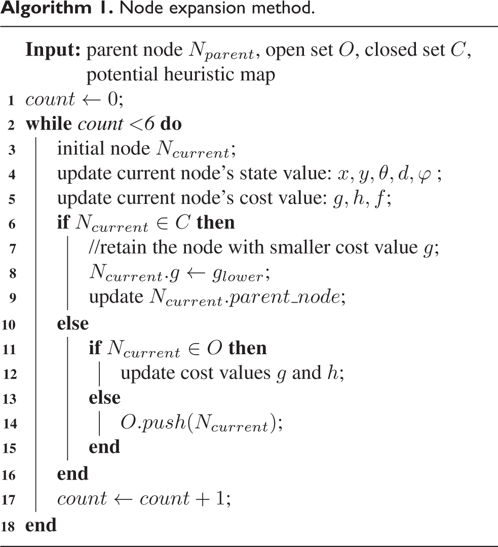
Node expansion method.

In conclusion, compared with the traditional hybrid A* method of wheeled robots, expanded nodes of our improved method contain information about not only position, orientation, forward or backward motion direction but also tilt angle
Collision detection
For robots with rectangular chassis like car, there are several ways for collision detection, as shown in Figure 7: rigorous numerical calculation for area sum of these four triangles consists of each side of the car and obstacle point P/Q compared with the area of robot. If the obstacle is not in contact with the car, the area sum will be greater than the area of the car itself or vice versa. In high speed or relatively less rigorous scenarios, to reduce calculation cost, the car can be covered with one or two circles by turning the problem into detecting the collision between obstacles and circles, which reduces the accuracy and searching completeness.
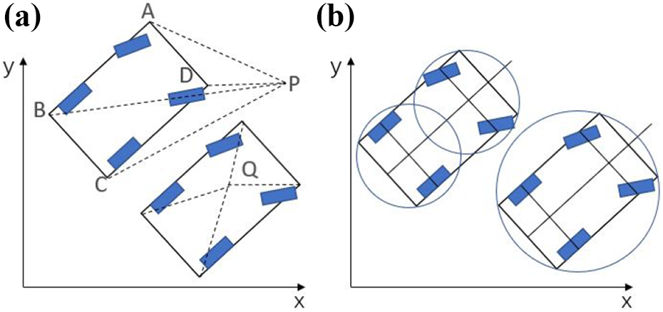
(a, b) Different collision detection methods of wheeled robot.
In comparison, the collision detection of spherical robot is relatively easier for calculation, because any part of spherical shell shares the same distance to the center of the ball (equal to the radius of the robot

Collision detection method of spherical robot.
Minimal area for rotation
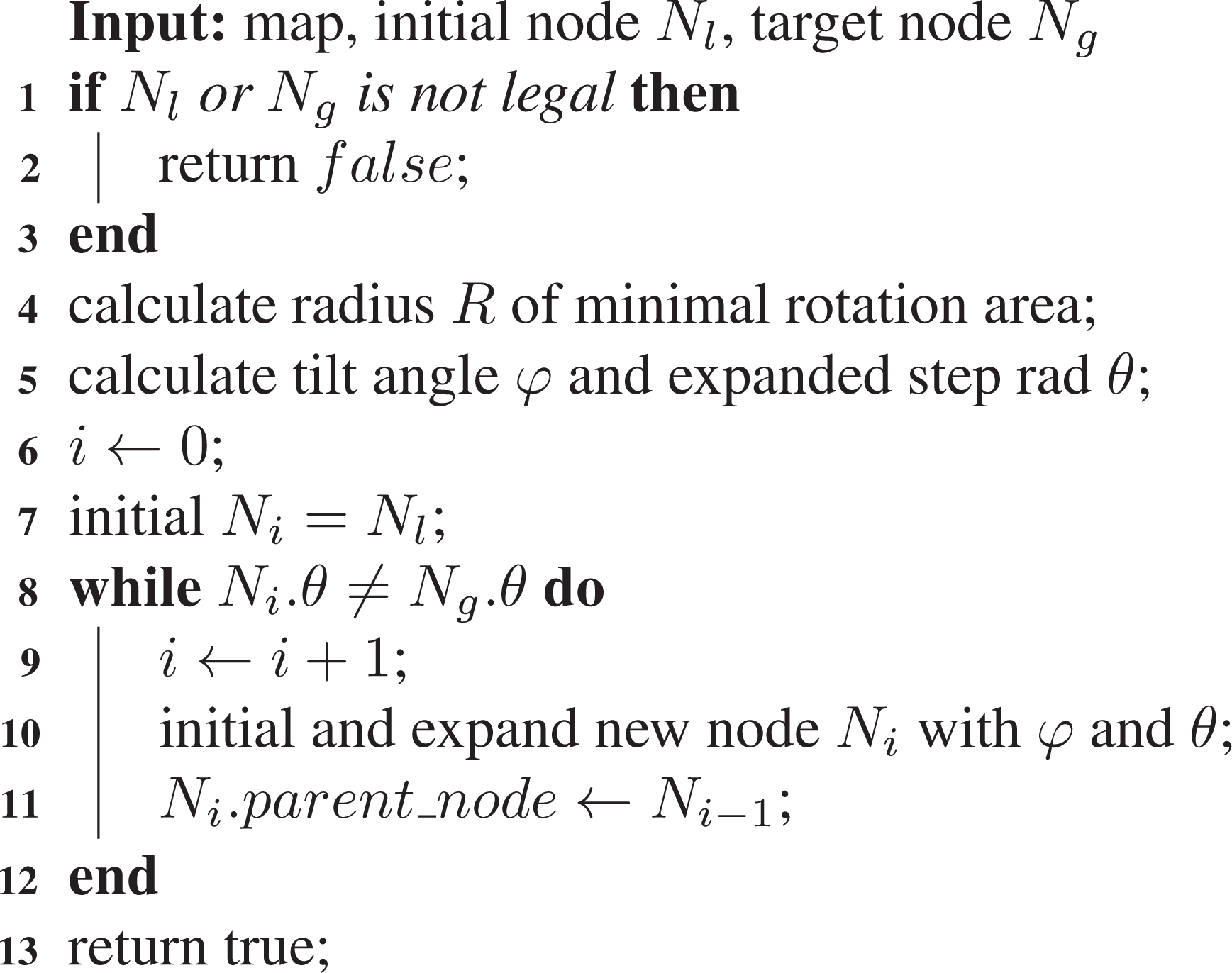
Compared with the traditional hybrid A* algorithm, our proposed improved hybrid A* search algorithm is appropriate for spherical mobile robots by changing node expansion strategy preserving kinematic constraints of spherical robot, whereas hybrid A* method cannot promise search completeness. So, although the improved node expansion method ensures that the generated path is kinematically feasible and pruned search strategy will improve the search cost, hybrid A* search will still face some scenarios that the whole search method fails because the open list is empty before reaching the final goal pose, which usually appears in narrow space surrounded with obstacles that the expanded nodes of the path coincide with each other. Another kind of scenario is that the robot recovers from distraction and needs to renavigate the surrounding areas, where a minimal area for rotation is needed to fully know about the surrounding environment with different kinds of attached sensors. As mentioned above in the section of collision-detection, compared with car-like robot, spherical robot has advantages that the orientation of spherical robot does not affect the collision-detection result if the center of robot is unchanged. Differential robot like sweeping robot can turn around in place with zero turning radius, and for spherical robot which has lateral movement while tilting and nonzero turning radius, in order to change orientation in a limited area, we proposed a concept of minimal rotation area for spherical robot according to the characteristics of its spherical shell.
As the hybrid A* search fails because of an empty open list, there is a certain expanded node Nl with the lowest heuristic cost h between the start and goal pose. Since there is a generated 2D A* path from Nl to goal position (heuristic holonomic path with obstacles for calculation of
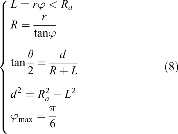
The proposed minimal rotation area for spherical robot is an area that ensures the robot to freely change its orientation toward any degree by rotation while keeping its center within this limited area. The distance of surrounding obstacles can be detected by sensors attached in robots like radars, lidars, or cameras when in narrow space. So, the robot can get real information around itself and calculate a free circle area, like a bubble, making sure that the robot can move collision-freely by keeping the center within this area. As shown in Figure 9, there are four actions of node expansion: combination of left/right leaning and forward/reversing. The initial pose is in (0, 0, 0), and the radius of robot is set to 0.3 m, tilt angle is set to

Minimal area for rotation of a spherical robot.
In general, if the lateral movement and expanded distance are shorter, the radius of minimal rotation area can be smaller, but to satisfy omnidirectional demand, the number of expanded nodes for a total rotation will increase and the cost time for changing the direction of both motors is to be considered. Meanwhile, the maximum of lateral movement


Optimal parameter diagram of optimal tilt angle
Minimal rotation method.

From Figure 11, we can find that the value and derivative of
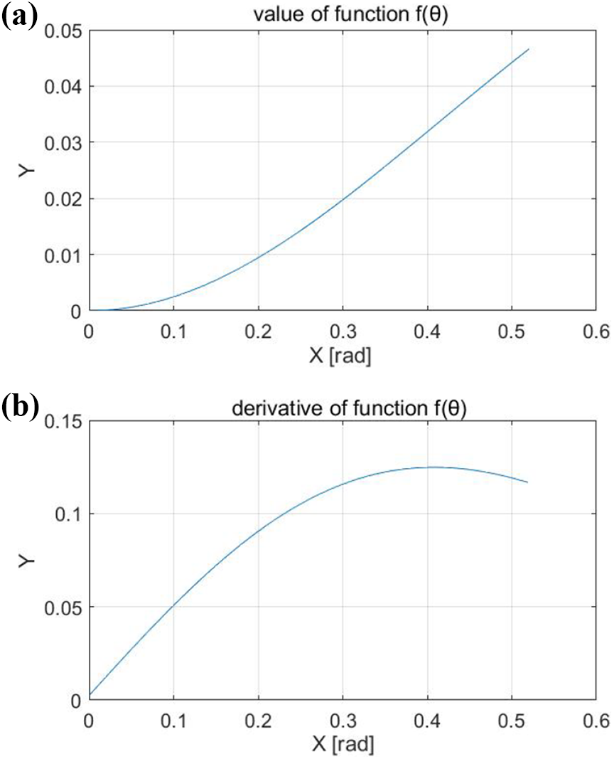
(a) Function value and (b) derivative of
Pathfinding algorithm
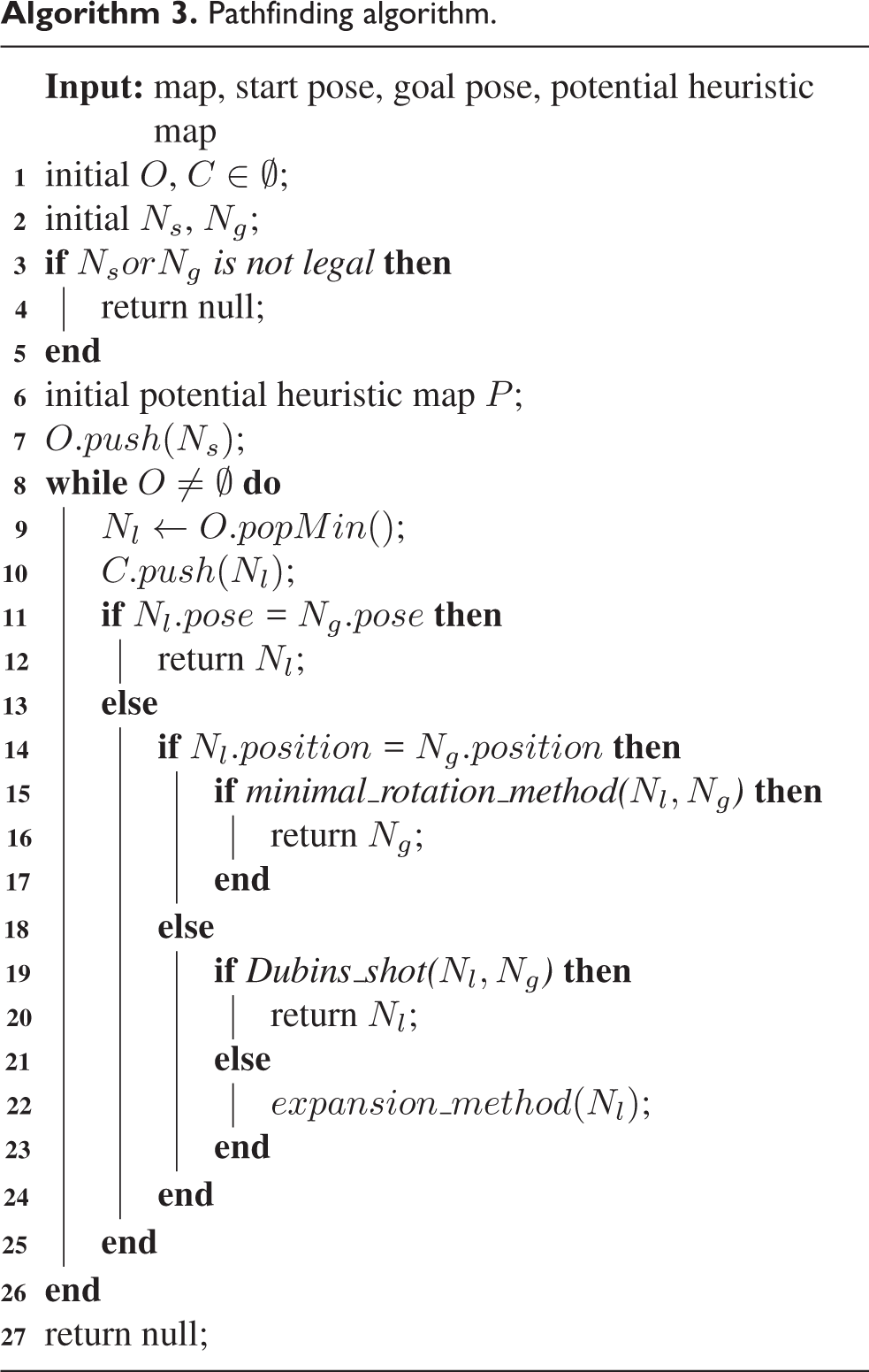
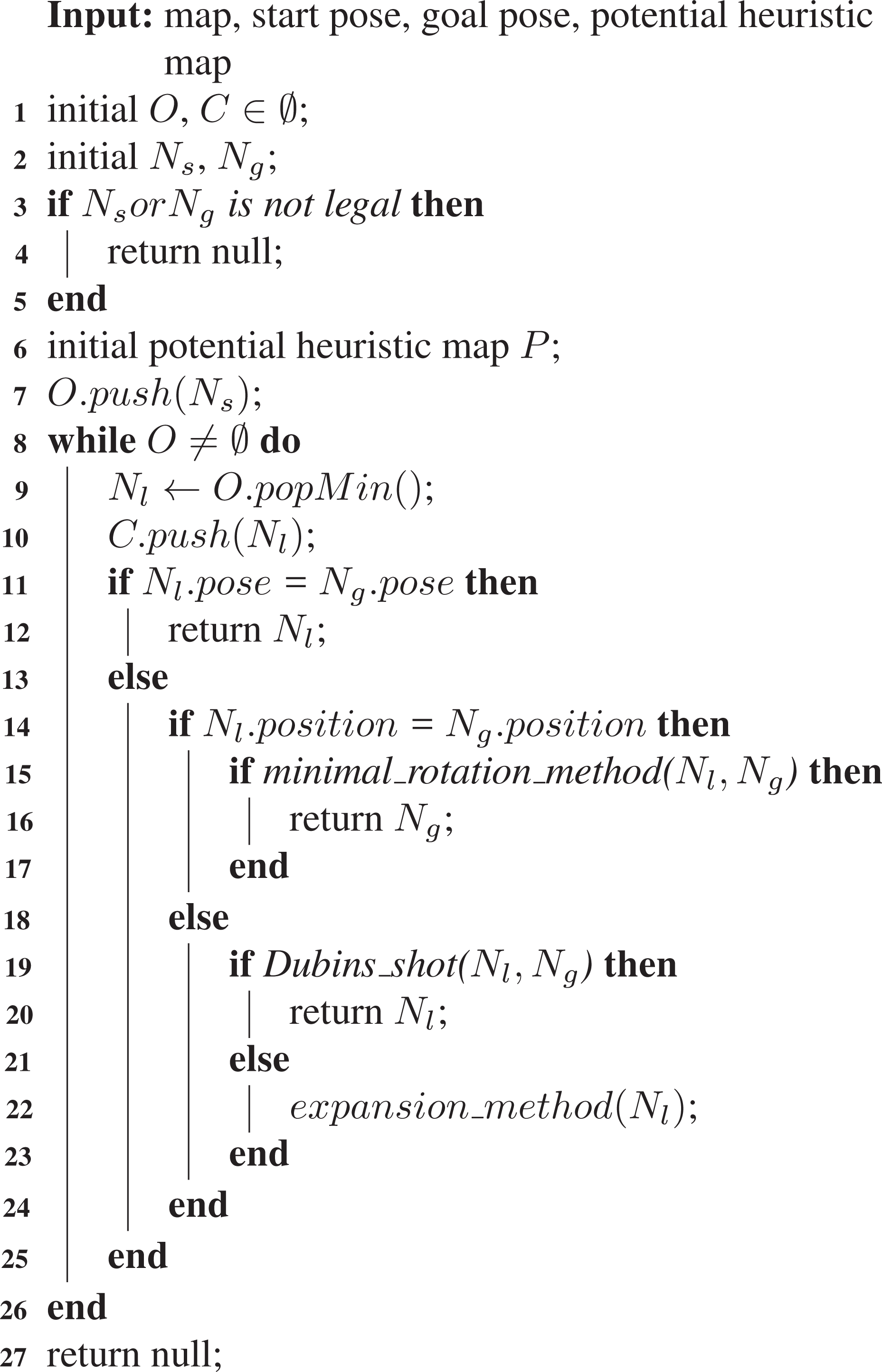
The basic model of our pathfinding algorithm is based on the traditional hybrid A* method, which can be summarized as maintaining a priority queue named Open list O. The whole pathfinding algorithm is illustrated in Algorithm 3. Given legal start and goal pose, the potential heuristic map P is initialed with an A* search from start grid to goal grid, recording holonomic estimated cost of every expanded grids. Ns is pushed into open list O, then the algorithm gets into while loop until O is empty or the goal is reached, as mentioned in the previous section: the node with minimal total cost f will pop from O and be pushed into close list C, then its potential legal (not expanded and collision-free) subnodes will be initialized and pushed into open list O iteratively, sorted by their total cost f from small to large. If potential subnode is already in O or C, its cost value g and h will be updated to retain more optimal node with lower cost value. Minimal rotation area method is applied when goal position is reached but with different orientation, Nl and Ng will be sent to Algorithm 2 and return expanded node if rotation method succeeds. Besides, there is a probability to generate a Dubins path connecting current expanded node with goal pose, and if the whole Dubins path is collision-free (which means we have already founded a path connecting start and goal pose) or the goal pose is already expanded, the hybrid A* search method ends with success, and finally, the goal node will trace back its parent node iteratively back to start node, generating the feasible path connecting start and goal pose.
Pathfinding algorithm.
As mentioned above, the pathfinding method needs to ensure real-time requirement. Meanwhile, the potential heuristic map ensures that there is a holonomic A* path for further node expansion. Since the improved hybrid A* search needs to record every expanded node, the iteration times of node expansion and the number of expanded nodes determine the time/storage cost. When it comes to open space, the hybrid A* search is relatively fast to expand nodes toward goal pose, whereas a lot of node expansion occurs in narrow space with reversing and forward/backward switch because these actions cause high cost g but low reduction of heuristic cost h. Although both nonholonomic with nonzero turning radius, compared with wheeled robot, spherical robot has some better characteristics: spherical robot has relatively smaller turning radius compared with wheeled robot with similar size and spherical shell which do not affect collision detection result for robot’s poses with different orientation.
Experimental results
The proposed system has many adjustable parameters. Simulation and physical experiments are both completed. The parameters of robot are as follows: the minimal radius for expansion
Simulation experiments
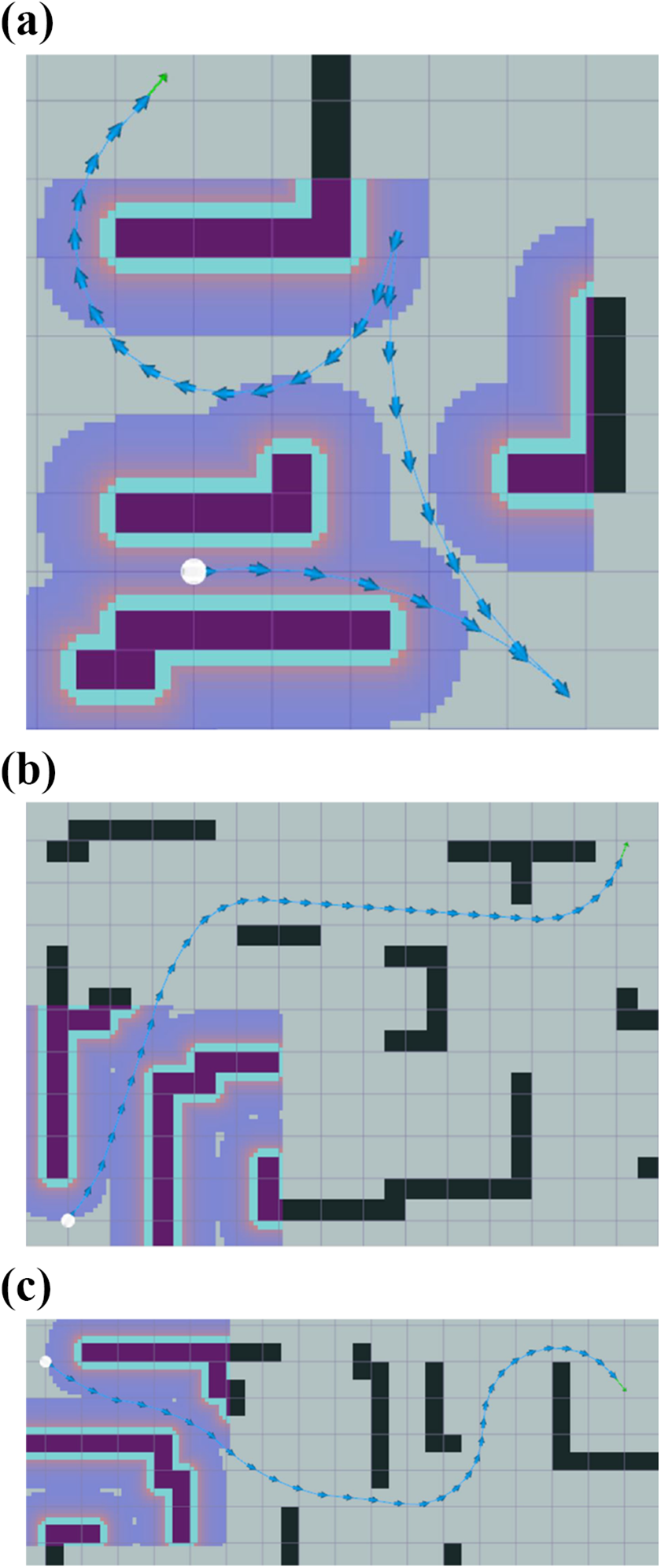
Simulation experiments are conducted in three different scenarios. As shown in Figure 12 of scenario 1, there are three paths generated by our improved hybrid A* path plan algorithm, feasible for our spherical robot, with the same start pose and same goal position but different goal orientation. All these three generated paths are feasible for spherical robot, whereas the smoothness of paths is different because of different goal orientation. Dubins path search succeeds in

Scenario 1: three generated paths (1), (2), and (3) with the same start node and different goal orientation: (a) Path (1), (b) path (2), and (c) path (3).
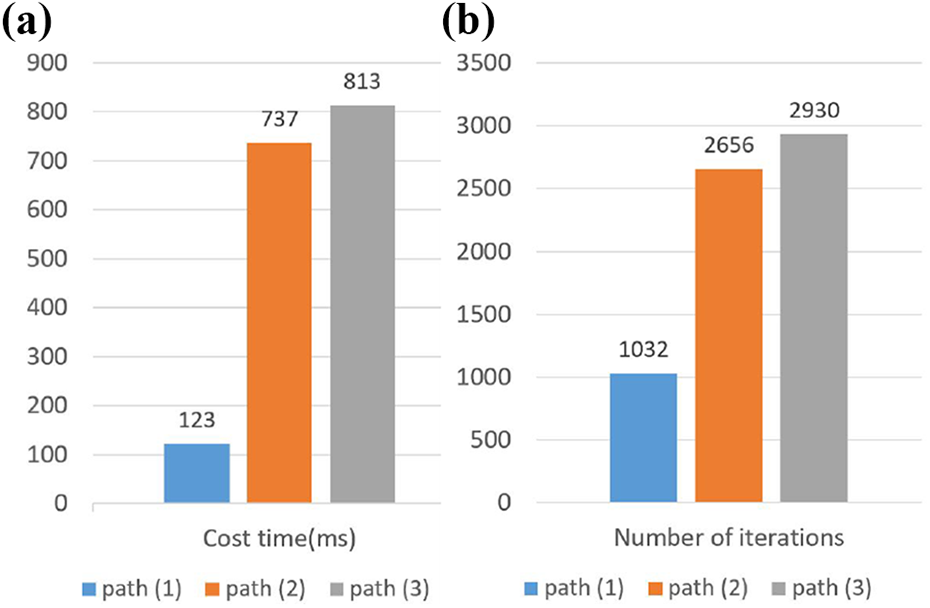
(a) Time cost and (b) iteration times comparison of three generated paths in Figure 12.
The three paths of scenario 2 in Figure 14 illustrate a typical example of different generated paths with/without applying minimal rotation area method.

Scenario 2: three generated paths (4), (5), and (6) with the same start node and different goal orientation: (a) Path (4), (b) path (5), and (c) path (6).

(a) Time cost and (b) iteration times comparison of path (4), (5), and (6).
Experiments results in maze scenario with larger scale and complicated obstacles distribution are shown in Figure 16. Table 1 records four metrics of simulation experiments for measuring performance. The value of path length is the sum of the distances of all adjacent nodes in the generated path, referring to a total distance of the generated path. The total degree of orientation change records the amount of rotational movement from the initial to goal node, measuring the smoothness of path. Time for path calculation is also recorded in parameter: cost time, which is crucial as the optimal algorithm must construct paths efficiently. Parameter direction switch shows the times of forwarding/reversing of the path. Since the velocity will change the sign in each switching point, the parameter illustrates the smoothness of motion speed. In scenario 1, the distance and orientation difference of initial and goal node are 9.55 m and 90°. In scenario 2, the distance and orientation difference of initial and goal node are 6 m and 180 °. Generated paths of
Results of simulation experiments.

Three generated paths (7), (8), and (9) in complicated maze scenario: (a) Path (7), (b) path (8), and (c) path (9).
Physical experiments
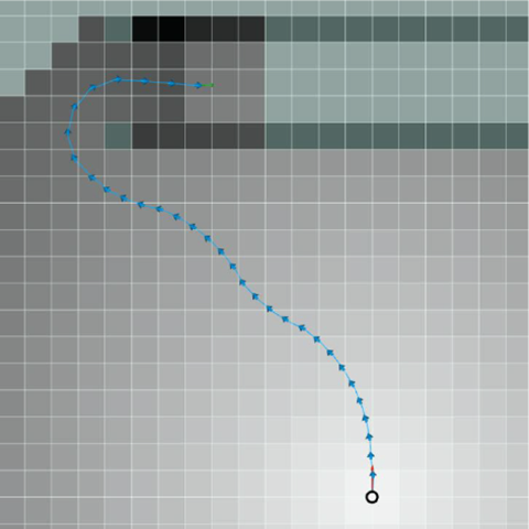
The physical experiments are conducted on flat ground surface environment. The general speed of the whole motion is set 0.6 m/s, and the scenario is similar to scenario of

Physical experiment 1 of spherical robot navigation: red arrows are recorded poses of spherical robot, black curves are generated local path: (a) physical trajectory and (b) local plan curves.
Another motion scenario is depicted in Figure 18, similar to scenario in Figure 13(b). Physical trajectory of Figure 18(a) consists of a series of red points showing location for better display and comparison between generated path and physical trajectory. The reason why the physical trajectory does not follow the green global guide path in narrow space is that local plan algorithm takes the distance of obstacles into consideration, shown in black curves and purple layer of Figure 18 (b). Because of repulsive force from obstacles, despite no risk of collision, the robot avoids being too close to obstacles of both sides. More complicated path containing direction switch is not evaluated in physical experiments because of the current limited local plan algorithm, which needs to be further studied.
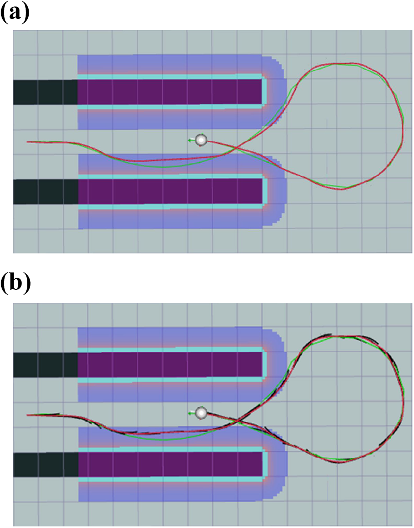
Physical experiment 2 of spherical robot navigation: (a) physical trajectory and (b) local plan curves.
Table 2 records parameters of both planned paths and actual trajectories in physical experiments mentioned above. Because of inevitable tilt during the whole motion, the path length and orientation change of actual trajectory are greater than the planned path. The cost time of path generation meets the real-time requirement, and the average velocity of our robot is slightly lower than the set speed (0.6 m/s). Recorded velocity data from motor encoders show that the actual speed will decrease while turning a corner. According to experimental data and comparison of planned paths and actual trajectories, the given paths generated by our proposed algorithm can be well tracked and can be the baseline of our future study.
Results of physical experiments.

Conclusion
An improved hybrid A* search algorithm is proposed for path plan of spherical robot. Firstly, we analyze the kinematic model of spherical robot and modify node expansion method by taking lateral movement and tilt angle switch into consideration. Secondly, inspired by differential robot with zero turning radius, minimal rotation area method is proposed for spherical robot to be used in scenarios that goal position is expanded but with different orientation, helping reach expected orientation with less expanded nodes and lower time cost. The proposed pathfinding algorithm takes not only the length of trajectory into consideration but also reversing condition, tilt angle changing, and forward/backward switch. Finally, simulation and physical experiments are conducted for evaluation of the algorithm. The search frequency of our proposed algorithm is guaranteed. Meanwhile, the generated path can iteratively be updated and published for path tracking of physical spherical robot.
Future studies mainly focus on three tasks: (1) Minimal rotation area method can also be applied in other scenarios to generate feasible path-like tight bend and small areas to adjust orientation. (2) Velocity optimization can be further taken into consideration along with path optimization, smoothing curves in open space, and adding speed limit to the entire path, considering curvature and change of motion direction. (3) Dynamic obstacles are not considered in our experiments. Meanwhile, physical experiments of more complicated paths containing multiple forward/reversing switch will be conducted in our future work list by applying more advanced local plan algorithm and control method in our spherical robot.
Footnotes
Declaration of conflicting interests
The author(s) declared no potential conflicts of interest with respect to the research, authorship, and/or publication of this article.
Funding
The author(s) disclosed the receipt of following financial support for the research, authorship, and/or publication of this article: This work was supported by the National Key Research and Development Program of China [No. SQ2019YFB130016] and the Fundamental Research Funds for the Central Universities.