
Abstract
According to the characteristics of human gait and the requirements of power assistance, locomotive mechanisms and electrohydraulic servo driving are designed on a lower limb exoskeleton robot, in which the miniaturization and lightweight of driving system are realized. The kinematics of the robot is analyzed and verified via the typical movements of the exoskeleton. In this article, the simulation on the power of joints during level walking was analyzed in ADAMS 2016, which is a multibody simulation and motion analysis software. Motion ranges and driving strokes are then optimized. A proportional integral derivative (PID) control method with error estimation and pressure compensation is proposed to satisfy the requirements of joints power assistance and comply with the motion of human lower limb. The proposed method is implemented into the exoskeleton for assisted walking and is verified by experimental results. Finally, experiments show that the tracking accuracy and power-assisted performance of exoskeleton robot joints are improved.
Keywords
Introduction
Walking assistants employed for joints comprise lower limb exoskeleton robots; these robots help boost human motion by utilizing intelligent decision making. The advantages of human–machine collaboration involve broad application prospects; further, this relationship exhibits considerable potential in weight-bearing walking on roadless pavements, walking assistance for the elderly and disabled, and gait rehabilitation training. Although exoskeleton robots are extensively studied, there are still enormous challenges regarding humanoid mechanical structures, human–computer communication, driving and controlling of joints, and methods to prevent tumbling.
In recent years, substantial progress have been made in both joint structures and the actuation of exoskeleton for assisted walking that are required to be consistent with the trajectories of joints. Generally, there are two driving types to generate the trajectory of joints: active power-assist and follow-up types. In active power-assist type, human–machine interaction is used for locomotive intensions, and then, the exoskeleton will be active for joints power-assist walking. Sensors, such as force sensors, torque sensors, and electromyography (EMG), are configured to detect the intended direction of human motion. Human joint motion could be estimated in real time. The exoskeleton rapidly follows the bone joints. In the follow-up type, exoskeletons follow the trajectories generated by human body motion. Mechanical design and the driving of joints for lower exoskeleton robot are also important studies that focus on improving tracking errors and power-assisted level walking. Compliant walking assistance and locomotion stability analyses are important studies on exoskeleton robot. 1
Furthermore, the driving mode, which decides the forms of motion of mechanical structures and the control methods, is the first issue that should be solved. From the perspective of joint driving, walking assistant and body movement enhancing mainly use hydraulic driven. In 2004, UC Berkeley presented an exoskeleton BLEEX that uses the hydraulic power unit. 2 The BLEEX has a rigid mechanical connection with the lower limbs of the human body. A high-accuracy dynamic model is used for a sensitivity amplification control method and the practical applications are limited.
Raytheon Sarcos announced XOS-1 and XOS-2, with 21 MPa driving force, in 2006 and 2010, respectively. 3 A hydraulic-drive lower limb exoskeleton was developed for military applications by Lockheed Martin that is named human universal load carrier (HULC). HULC could sustain large loads and replicate the movement of the human lower limb.
The lower limb exoskeletons employed to assist the elderly and disabled walk as well as for rehabilitation training are based on electromagnetic servo driving. Based on BLEEX, UC Berkeley announced Ekso Bionics-eLEGS and the corresponding improved series during 2014–2017. 4 Rex Bionics developed an exoskeleton (REX) to help disabled people in wheelchairs as well as REXP, an alternative that could be used in households. These two models were experimentally tested in Amana Healthcare. 5 From 2013, Yaskawa Electric along with ReWalk Robotics developed a lower limb exoskeleton robot for locomotion assistance as well known as the ReWalk. Hybrid-assisted leg (HAL) was introduced by the University of Tsukuba, and then, the license for selling the product in the United States was obtained in March 2018. HAL uses many electrodes to obtain EMG signals to calculate the torques of human joints and replicate human locomotion. 6
The HIT-LEX exoskeleton was designed in Harbin Institute of Technology that corroborated its efficiency in power-assisted load walking. 7 An active power-assist lower limb exoskeleton with a new structure is designed, which can detect the human body motion in real time to calculate muscular torque. 8
A new generation of exoskeleton robot with variable stiffness has been developed, which is equipped with a multisensor detection platform and combined with deep learning algorithm, making new research progress in human–robot interaction force and joint tracking. China Northwest Institute of Mechanical and Electrical Engineering designed an exoskeleton using hydraulic driving in 2014. In 2017, a hybrid power unit is supplied to exoskeleton robot. 9
A hydraulic linear actuators are used in the wearable robots for increasing payload capacity. 10 At the same time, there are many electrically exoskeleton robot-driven, such as the LLEX, in which a fast parameterized gait planning method could be used in this lower-limb exoskeleton robot. 11 To improve walking compliance, series elastic actuators are used in the exoskeleton with the methods of estimating contact forces and moments. 12 A motion-phase-based PID controller is designed for the lower limb exoskeletons, in which the performance of stability and robustness is verified by experiments. 13
For walking assistance, higher level demands include torque control and power–mass ratio. Most exoskeletons are hydraulically driven, which are more extensible in response speed and overload resistance. Compared with motor-driven joints, there are a few problems in electrohydraulic servo-driven exoskeletons, such as nonlinearity control, inherent hysteresis, and integration. Furthermore, the hydraulic driving cylinders work as the parts of the joint structure; therefore, we are required to drive the linkage mechanism directly and make it consistent with the range of human motion. This results in limitations of motion ranges.
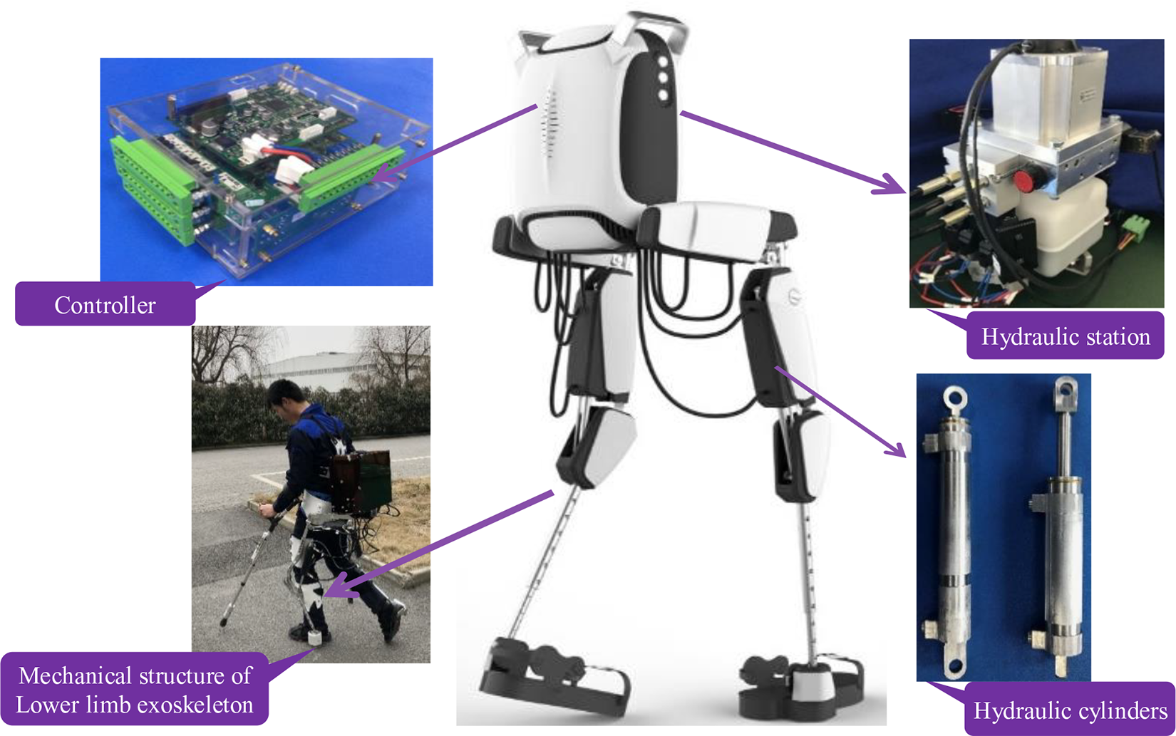
In this article, the locomotive mechanism of exoskeleton is designed and simulated based on the characteristics of human-level walking. Also, an electrohydraulic servo driving is designed for the exoskeleton joints, and the miniaturization and lightweight of the driving system were realized. Then, a PID control method of exoskeleton robot joints based on error estimation and pressure compensation is proposed to improve tracking accuracy and smoothness for walking assistance. Finally, the proposed method is implemented into the exoskeleton robot for assisted walking and is verified by experimental results. Experiments show that the tracking accuracy and power-assisted performance of exoskeleton robot joints are improved. The electrohydraulic servo driving and wear effect of the exoskeleton are shown in Figure 1.
The rest of this article is organized as follows: the locomotive mechanism of exoskeleton is designed and simulation of human-level walking is introduced in the second section. Design of electrohydraulic driving servo system has been introduced in the third section. In the fourth section, a PID control method of exoskeleton robot joints based on error estimation and pressure compensation is proposed to improve tracking accuracy and smoothness for walking assistance. The experimental results and analysis are described in the fifth section. Finally, conclusions are drawn in the sixth section.
Design on joints and driving analysis of exoskeleton
Mechanical design on joints of exoskeleton robot
To ensure comfort when worn and human–robot coordination, the exoskeleton should replicate human joints although the arthroses of human lower limbs are relatively complex. Meanwhile, the lower limb motion occurs in the sagittal plane and the joint driving torque is large, which maintains balance in the coronal plane, and the driving torque of the joint is small. Combined with biomechanical characteristics, the joints of lower limbs, namely hip, knee, and ankle, could be abstracted from the complex biomechanical model of the human body. 14
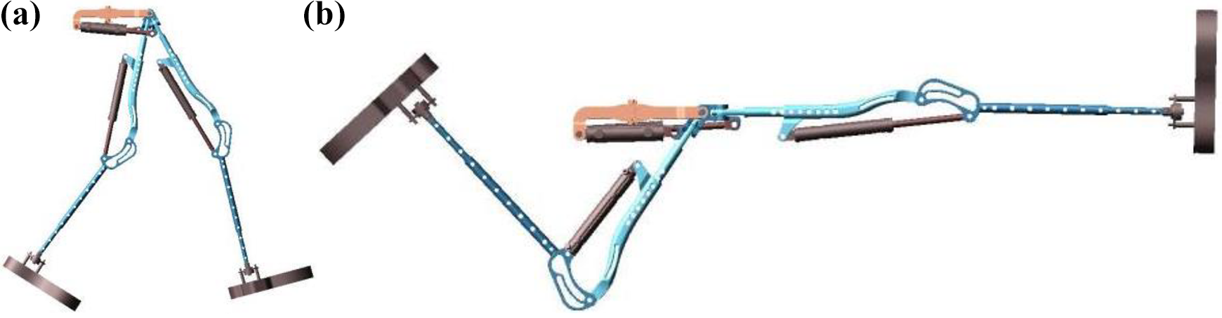
The exoskeleton structure is complicated when each joint of the lower limb is configured driving in degree of freedom (DOF). However, human walking occurs in the sagittal plane with a wide range of motion and demanding for driving power of the hip joint and driving torque of the knee joint. Furthermore, the motion range and driving force required in the coronal plane is low, whose main function is to maintain balance. Therefore, only the joint of DOF in the sagittal plane is considered, that is, hip joint and knee joint DOF in the sagittal plane are allocated to power drive. The DOF of the joints in the coronal and horizontal planes adopts the passive driving mode, namely driven by the wearer. The ankle joint is the final motion in the movement chain for exoskeleton. The ankle joint is configured as a passive DOF, that is, the ankle joint adopts a flexible passive joint, which makes the best use of the advantage of man-in-the-loop, ensures balance is maintained, and alleviates the difficulty of mechanism design and control. Thus, articular actuations are provided only in the sagittal plane of the exoskeleton and the coronal plane mechanism is used as the passive joint. According to the characteristics of human lower limbs and exoskeleton joint mechanism, there is only one driving DOF in hip and knee joints, respectively. We adopt a ball-and-socket structure in ankle joint, which is a passive joint with three DOF. The mechanical design of the lower limbs exoskeleton is shown in Figure 2, and the details of design of the three joints are shown in Figure 3. A crank slider mechanism was used for hip joints that could extend by 87° and flex by 34°. Furthermore, the locomotive range of the knee is 0–100°. With ball hinge and restraint ring, the ankle is a passive joint for −20° to +20°. Thus, it could provide assistance for human gait as well as other routine motions such as sitting down.
Design on electrohydraulic servo driving system for lower limb exoskeleton.

Mechanical design of lower limb exoskeleton robot.
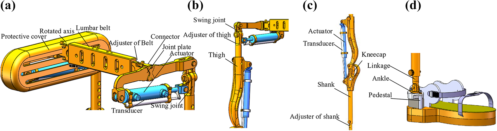
Design on joints of exoskeleton: (a) hip joint, (b) thigh, (c) shank, and (d) ankle.
Kinematics analysis of mechanism joints for exoskeleton
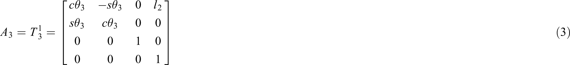
The lower limb exoskeleton could be treated as a three-bar linkage mechanism, and its kinematic model is shown in Figure 4. The D-H method was used to set up coordinate system, which is fixed in each joint. According to Figure 2, the absolute coordinate system is located at the center of waist as O0-x 0 y 0 z 0. Rotating coordinates are linked to the joints, such as O1-x 1 y 1 z 1 fixed in the hip joint, O2-x 2 y 2 z 2 fixed in the knee joint, O3-x 3 y 3 z 3 fixed in the ankle joint, and O4-x 4 y 4 z 4 fixed at the end point of toe. It is xi coincident with the axis of the joint, y i is orient to the extend cord, z i is ensured by the right-hand rule. The rotated angles of the joints are θ 21, θ 22; they are rotated about x-axis and z-axis, respectively, in the local coordinates; the angles that rotated about the x-axis knee and ankle are θ 3, θ 4.

Define coordinates on exoskeleton with D-H method: (a) local coordinates when standing and (b) local coordinates when walking.
There were two segment lengths of l 11 and l 12, respectively, in first linkage, which is the “L” shape, namely No. 1 bar linkage. The second linkage of No. 2 bar is used between the rotated joints of hip and knee with length of l 2. No. 3 bar linkage is used as knee to ankle with length of l 3. No. 4 bar linkage is used as knee to ankle with length of l 4. Thus, the kinematic coordinates for single leg of the exoskeleton are shown in Figure 4


The absolute coordinate pose matrix of the ankle is as follows

Therefore, the homogeneous transformation matrix from the ankle coordinate system O4-x 4 y 4 z 4 to the belt central coordinate system O0-x 0 y 0 z 0 is

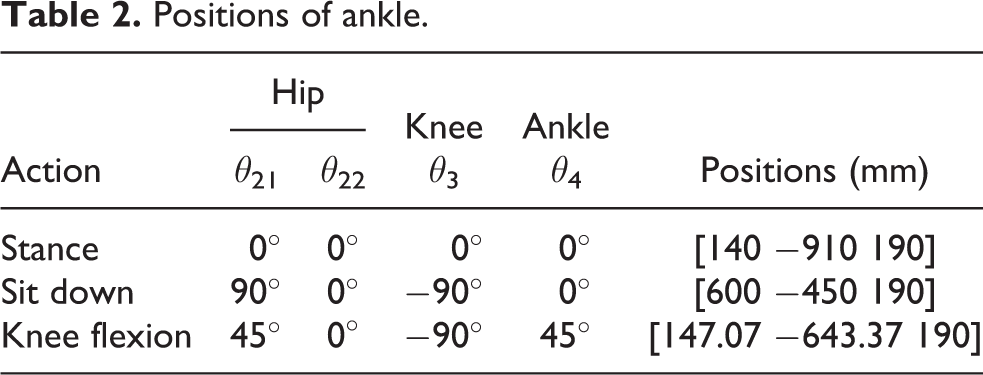
The linkage lengths and angles of joints are listed in Table 1. According to the kinematic analysis and calculation, the absolute positions of the toe when the exoskeleton completes the typical actions are summarized in Table 2. The positions of the ankle are transformed from local coordinates to global coordinates (absolute position in Table 2) after completing a few typical actions that include standing, sitting down, and knee flexes to verify the kinematics analysis. The results of the kinematics calculation are in accordance with the actual situation. The designed joints of the exoskeleton could satisfy the requirements for typical locomotion of human lower limbs such as level walking or deep squat.
Linkage parameters of joints of exoskeleton.

Positions of ankle.
Demands analysis of lower limb walking assistant
Lower limb horizontal moving gait and joint analysis
The lower limb exoskeleton should satisfy the parameters that define the walking motion of humans, including joint angles as well as torque and power of the human lower limb. Because we only equip four actuators in hip and knee joints, the analysis is limited to these two joints.
Human lower limb gait is shown in Figure 5. The four phases of this procedure are “Double limb stance” → “Swing” → “Toe-off” → “Heel-contact” → “Double limb stance,” and the joint angles, driving torque, output power, as shown in Figure 6. 15,16

Gait cycle of right foot when human lower limb is level walking.
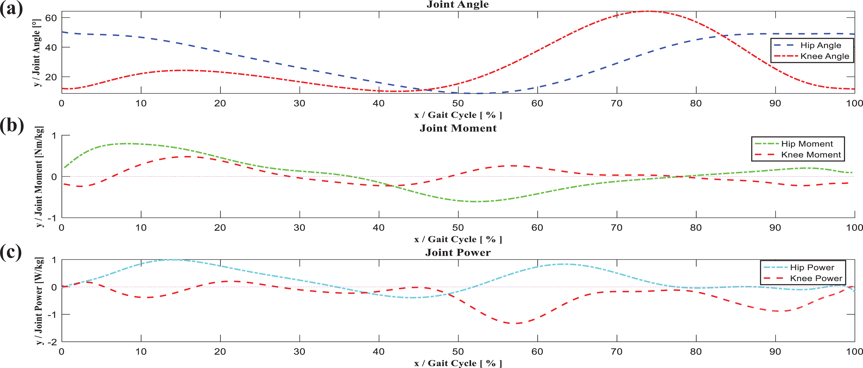
(a) Joint angle, (b) joint torque, and (c) joint power of lower limb when human level is walking.
According to the properties of gait and the control demands, the hip joint realizes two actions: bending and extending. To protect the knee joint, they only exhibit the bending action. Hip and knee joints have positive and negative energy outputs with large and small moments, respectively. For the driving system, on the one hand, the stroke of the motor should match the lower limb motion range; on the other hand, the moment and power should match the requirement of walking assistance. 17 Considering the joint data, joint angles, moments, and power curve are all nonlinear, which increases the requirement for the driving system. 18 Figure 7 shows the simulation of the lower limb level walking by ADAMS, which is a multibody simulation and motion analysis software.

Simulation on exoskeleton for power assistant when human level is walking.
The simulation sets the leg mass and center of mass of the upper limb while matching with the joints and the center of mass of exoskeleton. We derive the joint angles, displacements of stroke, joint moment, and power under the influence of lower limb level walking. The parameters are provided in Table 3.
Parameters of exoskeleton during level walking the level.

Simulation on exoskeleton for walking assistant
We construct the mapping among joint angles, power, moments, and stroke of the hydraulic cylinders, driving force, and outpower. Then, we use them as the input parameters of the driving system. 19
According to the walking assistant procedure, ranges of joints were optimized for the driving stroke, as shown in Figures 8 and 9. The walking assistant parameters of the exoskeleton are decided by the system simulation method. We build a three-dimensional model of an exoskeleton with human size and weight after finishing the integrated design of the mechanism and the joint drive.
Stroke of hydraulic cylinder for locomotion configuration: (a) Exoskeleton of level walking and (b) the maximum range of locomotion of exoskeleton.
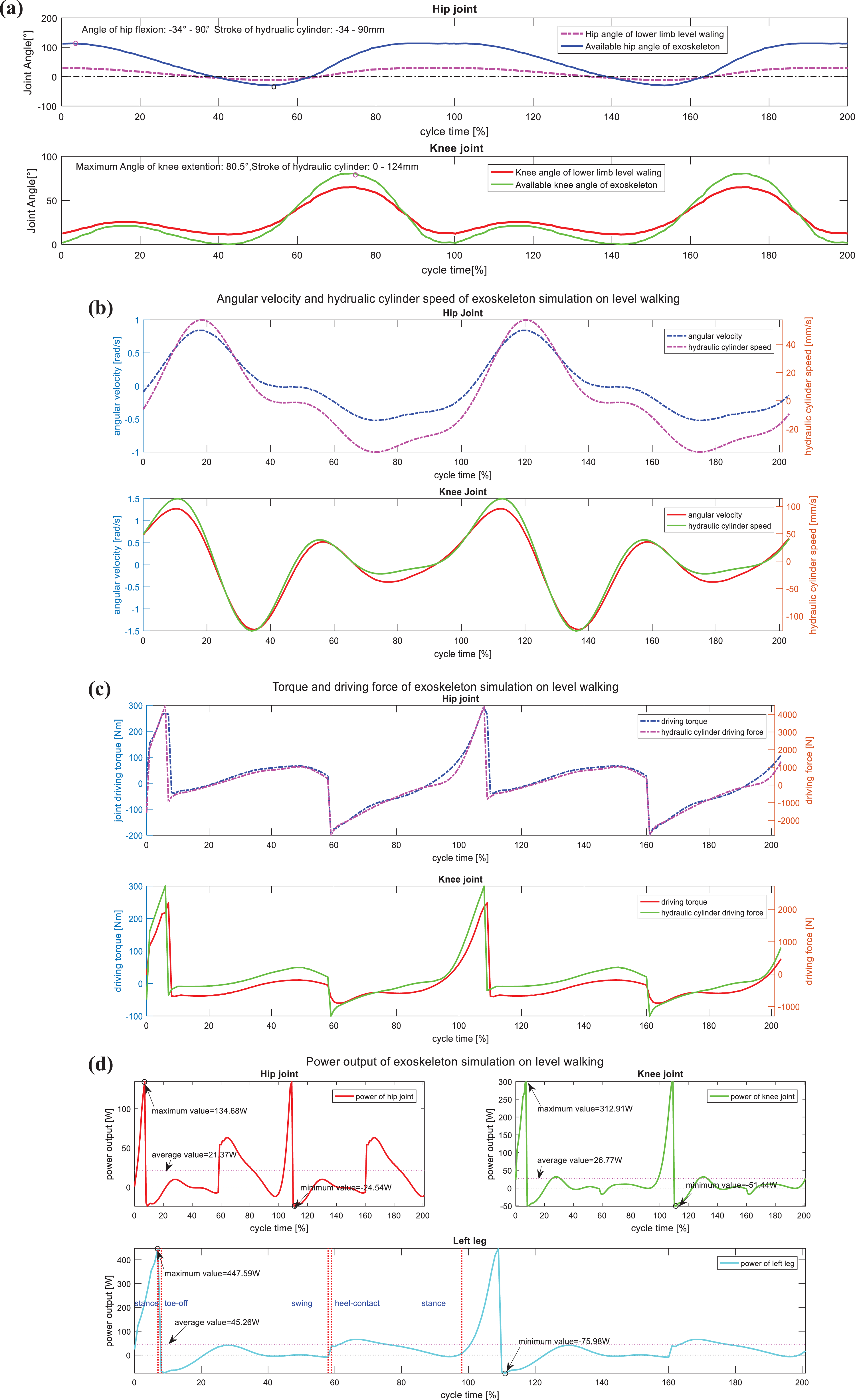
Exoskeleton-assisted robot simulation for level walking in Adams—joint angle, torque, and power: (a) stroke of hydraulic cylinders on exoskeleton matches the angle of lower limb, (b) angular velocity and cylinder speed of joints, (c) joints torque and force of cylinders, and (d) joints power assisted.
The simulation proceeds with the following steps: (1) 3D models of the exoskeleton are constructed in ADAMS. (2) The thigh, shank foot, and belt are configured as 19.5, 15.6, 7.8, and 24 kg, respectively, which is according to the mass distribution of the human body and exoskeleton. Thus, the entire mass of the exoskeleton is configured as 100 kg. (3) According to the design of the mechanical structure of the exoskeleton, the DOFs and motion of the joints are defined. Joint driving is added with the generated trajectory. Data of the joint variables are provided for walking in Figure 7 and then the simulation is completed. Optimization of the joints of the exoskeleton and strokes. Based on the lower limb walking requirements, besides the level walking, the exoskeleton should meet all the requirements of various actions, such as squatting and climbing steps. The hip joint could be locomotive from 34–90°, and the knee joint could bend from 0° to 80.5°. After optimizing the stroke of the hydraulic cylinders, the strokes of the hip and knee joint hydraulic cylinders are −34 to 90 mm and 0–124 mm, respectively. Allocation of the power of the electrohydraulic servo system for the exoskeleton. The average power in the hip joint, knee joint, and left leg is 21.37, 26.77, and 45.26 W, respectively, in the assistant procedure. The total output power is approximately 45 W. However, in the simulations, owing to the impact action in the phase of heel-contact, the joint torque and power increase sharply and the maximal power of the exoskeleton reaches 447.59 W.
Design of the electrohydraulic servo system
Relative to level walking in humans, the power and torque of the joints change rapidly, as shown in Figure 7. Thus, we have developed the hydraulic driving system because of its impact resistance and overload performance.
Based on these simulations and the mapping between the walking assistant and the design of the hydraulic servo system, the electrohydraulic servo system for the exoskeleton could be divided into three modules, the hydraulic base station, energy recovery, and joint drive. These are shown in Figures 10 and 11.

Design of the electric-servo driving system for exoskeleton.

Hydraulic station of electric-servo driving system.
Hydraulic station
The hydraulic base station provides the power for the entire exoskeleton. To resolve the problems of frequent reversal, high instantaneous pressure, and large instantaneous power, we use a closed hydraulic circuit in the hydraulic base station to satisfy the working conditions for small flow rate with high instantaneous pressure and large instantaneous power.
The hydraulic base station includes servo motor 3, gear pump 5, soft tank, filter, and proportional relief valve 14, and they are all fitted into the central valve block. The flow is controlled by the gear pump 5 through servo motor 3 to adjust the hydraulic workflow, and proportional relief valve 14 sets the outlet pressure of the base station.
The parameters of the hydraulic base station are provided in Table 4. The rated speed of the motor is n = 2000 r/min, the gear pump displacement is V c = 3.5 mL3/r, the working speed is 650–2000 r/min, the volumetric efficiency of the pump is η v = 94%, and the mechanical efficiency of the pump is η m = 87%. The entire efficiency is η t = η v × η m = 82%. During the walking assistant procedure, the torques and velocities of the joints change rapidly in the single limb and double limb stances. According to the experiments, we selected two speed settings with pump outlet pressures of 5 and 3 MPa, respectively. The corresponding speeds are 2000 and 800 r/min.
Parameters of hydraulic station on the exoskeleton.

Energy recovery
According to lower limb walking, the knee joint shows a negative energy output; some of these outputs are fed back to the hydraulic system. Aiming to address the problems of frequent reversal, complicated working environment, high instantaneous pressure, and large instantaneous power, we design an energy recovery module that can improve energy efficiency, reduce conversion loss, and smooth the shock and pressure wave. 14 This module will select an operation mode according to the gait information to adapt to the flow rate and pressure of the joints.
In a double limb stance, the flows in the left hip, left knee, right knee, and right hip are all small. We can set the electromagnetic directional valves 20.1 and 20.2 in the left positions and the hydraulic control directional valves 22.1 and 22.2 in the left positions. Redundant oil flows into accumulators 15.1 and 15.2.
In the walking phase (e.g. the left leg is in swing and the right leg is in a stance), the hydraulic cylinders of the left hip joint and the left knee joint require a large oil flow rate; the controller sets the electromagnetic directional valves 20.1 and 20.1 in the left positions and the hydraulic control directional valves 23.1 and 23.2 in the right positions. Accumulator 15.1 provides energy to the driving module, and the pump working with the accumulator can realize a lower working flow rate to ensure the working condition and recover the energy.
In the heel-off phase, the maximal impact force is approximately four times the weight, and the exoskeleton has a greater impact. At this moment, the electromagnetic directional valves 20.1 and 20.2, as well as the hydraulic-controlled directional valves 22.1 and 22.2, are in the left positions. Redundant oil in the joint-driving module will flow back into accumulators 15.1 and 15.2. This can reduce the impact and render the system more stable.
Design of the joint driving
To maintain control flexibility, four driving joints are controlled independently. Using the proportional servo valve to adjust the flow secondarily, the joint speeds can be precisely controlled.
The control flow of the joint driving is as follows: the control system drives DC servo motor 3, and the servo drives the two-way variable displacement hydraulic pump to enable the oil to flow into the electromagnetic valve 20 (20.1, 20.2) through the silencer. When the electromagnetic valve obtains the power, the valve core is in the right position, and the oil-way is connected with the electromagnetic proportional servo valve 16 (16.1, 16.2, 16.3, 16.4) of the driving leg. When the electromagnetic proportional servo valve is out of power, it is in the median position, the inlet is closed, hydraulic cylinder 17 (17.1, 17.2, 17.3, 17.4) has equal pressure in the left and right cavities, respectively, and the piston does not move. When the proportional servo valve is controlled to move to the right, the oil enters the rodless cavity, the oil returns to the rod cavity, and the piston moves to the right. The encoder18 (18.1, 18.2, 18.3, 18.4) converts piston position information into counting pulses, force sensor 19 (19.1 and 19.2, 19.3 and 19.4, 19.5 and 19.6, 19.7 and 19.8) detects the pressures at the outlets, and the counting pulses and the pressures, as the detection signal, are transferred to the controller.
For example, when the proportional servo valve controlled by the input signal is in the left position, the hydraulic cylinder with the piston moves to the left. The speed and the propulsive forces of the piston are calculated as follows

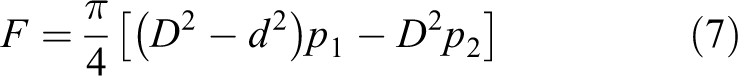
In this equation, D is the piston diameter of the hydraulic cylinder and d is the rod diameter. p 1 and p 2 are the pressures at the inlet and outlet of the hydraulic cylinder, respectively. F is the propulsive force and v is the hydraulic cylinder volume. Assuming that the working pressure is 5 MPa, the joint parameters of the hydraulic cylinder are given in Table 5.
Parameters of hydraulic cylinders.
Motion tracking of the exoskeleton joint based on pressure compensation
The hardware control channel of the knee joint of exoskeleton is shown in Figure 12. The external load of the hydraulic system is dynamically changed, and there is greater inertia in pressure switching and flow control. It is difficult to determine the displacement of the hydraulic cylinder and realize motion tracking by only using PID feedback control. 13,20

PID control for knee joint of exoskeleton.
The torque and power of the joint change rapidly during assisted walking, which sets high requirements for the amount of assistance, the joint velocities, and the system stability. Based on conventional PID control, we divide complete gait into four phases, that is, heel-contact, swing, toe-off, and double limb stances, and set four groups of PID control parameters. 17 Level walking of exoskeleton test for hydraulic driving is shown in Figure 13. To reduce the tracking error caused by phase switching of gait, we propose a joint motion tracking method based on pressure estimation and compensation. Further, this method could inhibit the shaking in motion tracking and realize smooth walking of the exoskeleton.

Level walking of exoskeleton test for hydraulic driving.
Essentially, the motions of the hip and knee joints are related, and when one parameter of these two joints is fixed, the other can be derived by mapping them; tracking can be then achieved. As the knee joint has a greater torque and motion amplitude, we use it as a typical joint for further discussion.
Analysis of displacement error of knee joint
Angular velocity of the joint
Angular acceleration of the joint

where θi is the angle of tracking joint at time t, if
The errors owing to hydraulic driving calculated by linear interpolation algorithm are

This algorithm could not help obtain the upper and lower bounds of the displacements, could not control the intermediate process simply, and has some uncertainties in the discrete tracking range. The ordinary linear interpolation algorithm based on PID control could not handle the situations of breakpoint and cusp, which may result in shaking and great tracking error. 21
PID control based on position error estimation with joints pressure compensation
According to the error, we modify the control term

And set the control term as
The membership function of the pressure compensation term of

where
This term is mainly used to compensate for the shaking caused by the external pressure. According to the different phases of the joint walking in the gait, we propose the correlation between the joint velocity and the required pressure of the hydraulic system, and give the correlation relationship as follows

Based on synchronous control of joint pressure and displacement, the matching effect and compliance of joint assistance were improved and shown in Figures 16 to 18.
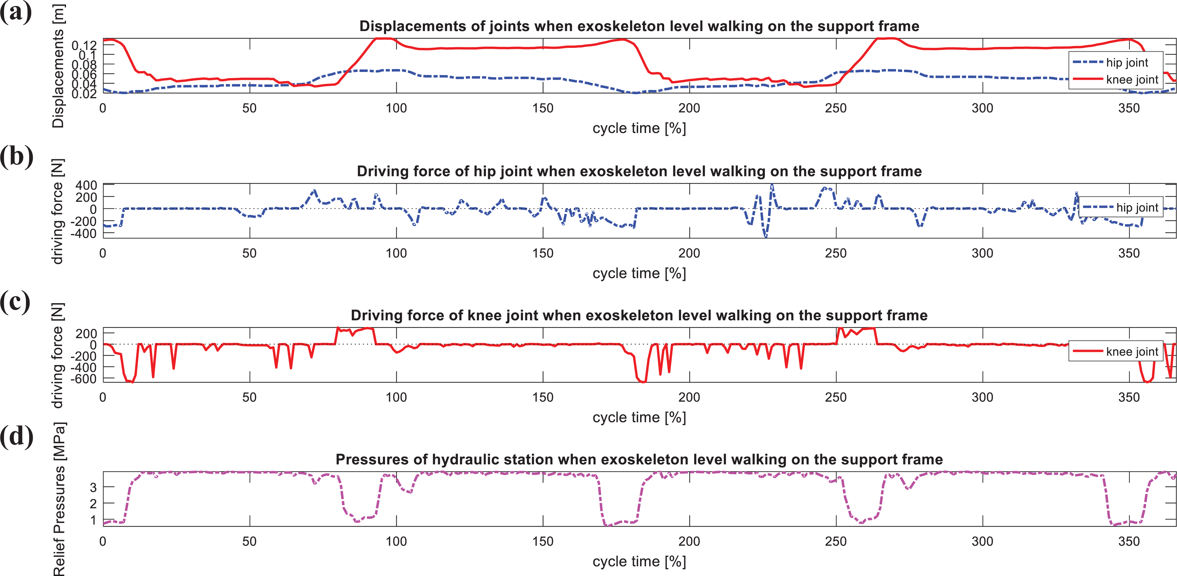
Conventional PID control of exoskeleton tracking the setting curve on the support frame (no-loading) for human-level walking: (a) Displacements of joints, (b) driving force of hip joint, (c) driving force of knee joint, and (d) pressures of hydraulic station.
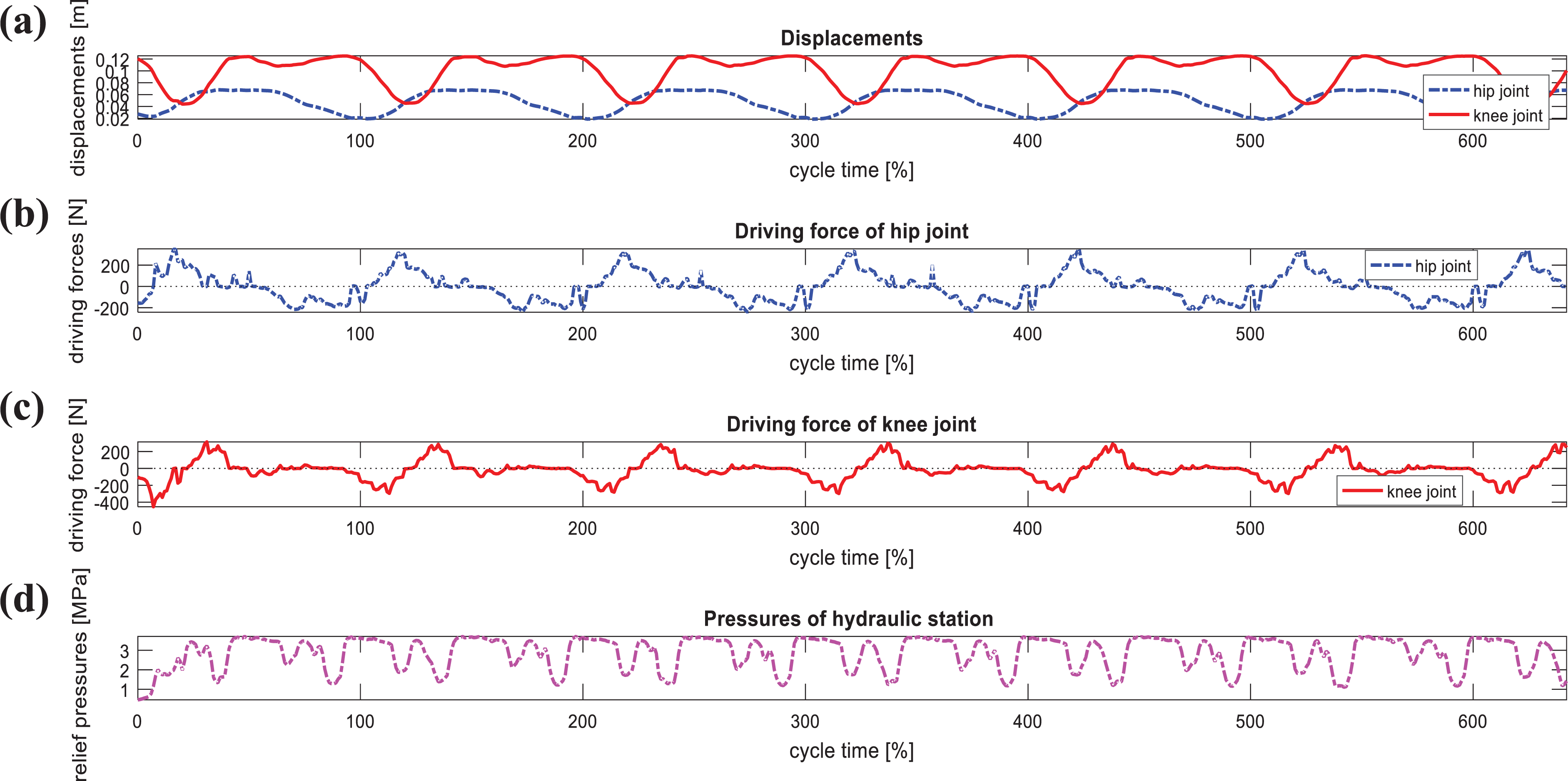
Parameters of hydraulic servo driving system when exoskeleton robot is leveling walking on the support frame (no-loading) (PID control with error estimation and compensation): (a) Displacements of joints, (b) driving force of hip joint, (c) driving force of knee joint, and (d) pressures of hydraulic station.

Wearing exoskeleton-assisted robot for lower limb when tracking the setting curve of level walking (PID with error estimation—PID—Setting curves of level walking): (a) Displacements of hip joint and (b) knee joint.

Lower limb is equipped with an exoskeleton robot for power0assisted level walking (PID control with error estimation): (a) Power of hip joint, (b) power of knee joint, and (c) power of left leg.

Power of exoskeleton and lower limbs for leveling walking (conventional PID control): (a) Power of hip joint, (b) power of knee joint, and (c) power of left leg.
The control term is fixed by the pressure that can facilitate the determination of the control system and adjust driving without frequent switching. The compensation term is

The Fourier fitting of the hydraulic cylinder angle curve during the walking phase is

In the last term, ω can be written as ω=1.54.
The real joint angle transferred by the displacement sensor signal of the hydraulic cylinder is

This term is used to compensate the tracking response error caused by the motion recognition and time delay in the control system.
To improve this feature, we propose a joint displacement control based on pressure compensation. According to the requirement of joint power in gait cycle, the outlet pressure of hydraulic base station is dynamically adjusted to meet the improvement requirement of power effectiveness.
In fact, the trajectory curve is determined by the flow rate proportional to the servo valve, and the inlet pressure of hydraulic cylinder is determined by the system hydraulic base station and proportional servo valve. Based on the period of gait, we can map gait partitions and PID parameters. Based on the displacements of the knee joint and the flow rate change in the hydraulic cylinder, the controller uses piecewise PID control; the control parameters are listed in Table 6. The period time from i to i+1 is set as 40 ms, which is obtained based on the type of the hydraulic valve and the frequency response of the motor. 22,25
Parameters of PID controller with error estimation and pressure compensation.

Experiments and analysis for exoskeleton walking assistant
The hip and knee trajectories of the exoskeleton with driving forces and outlet pressures of the hydraulic station are shown in Figures 14 and 15, which are under the control of conventional PID and PID with error estimation, respectively.
Figure 14 shows the working exoskeleton without loading. Using a conventional PID control without pressure estimation, and after optimizing the PID parameters, the joint can follow the designed curve; however, it shakes owing to the joint motion.
Figure 15 shows the PID control based on joint pressure estimation. The joints could follow the designed curve, and the PID with error estimation exhibits a better control effect and smoothness with small fluctuation in the driving pressure.
It could be preliminarily seen that, along with the gait phase mapping, the PID control with error estimation improved the tracking accuracy and smoothness for the exoskeleton joints during level walking. In addition, the driving force of the joints was smoother. The outlet pressures of the hydraulic station affect the driving of the joints, which can be clearly observed. The quantitative analysis of the exoskeleton, which power assists human-level walking, is compared below.
Figures 16
to 18 show the displacement tracking curve, pressure estimation-based PID control, and conventional PID assistant power for a 72-kg wearer in the level walking assistant case, respectively. The total weight of the exoskeleton is 30 kg. The weight of the researcher who wears the exoskeleton is 72 kg. The total weight was approximately 100 kg. From these experiments, we found the following: 1. The exoskeleton could follow human motion well; however, it has some fluctuations in joint displacement tracking. The tracking error of the hip joint is the maximum in 70–80% of the gait period, that is, 35% in support phase. The tracking error of knee is the maximum in 30–50% of the gait period, that is, 66% in swing phase. In the later of swing phase of the left leg, the tracking error of hip and knee joints is minimum in 60–70% and 40–50% in the gait period, respectively.
In the conventional PID control case, by comparing unstable walking with smooth walking, we confirmed that the error analysis is accurate, and the pressure fluctuation was large in the 20–40% of the gait period. 2. The joint displacement curve is clearly improved, and this curve was followed when the exoskeleton is worn. The error of hip is the maximum and minimum at 76% and 67% of the gait period, respectively. The minimum was approximately 0.17%, and the tracking accuracy was within 99.63%. The error of knee is the maximum and minimum at 10.29% and 30% of the gait period, respectively. The minimum was approximately 2.91%, and the tracking accuracy was within 93.7%. The error mainly arises owing to the response speed of the exoskeleton. 3. PID control with the compensation term will get better control effect, the shaking of the exoskeleton could be inhibited effectively, and smooth walking could be achieved. 4. In PID control with error estimation, the minimum power for the left knee joint was at 12% of the gait period. The assistant power was −66.588 W. The hip joint achieved the maximal output power 69.277 W at 8% of the gait period. The average output power of a single leg was 38.035 W.
In summary, the PID control with the error estimation follows the gait well and compared with the horizontal movement of the lower limb moving, the knee joint has a 65.16% power assistant effect. The single-leg assistant power is approximately 33%. Considering the energy conversion efficiency, the assistant ratio can be improved further.
From the PID walking assistant power figure, we find that in bad control circumstances, the exoskeleton has large output power, the knee joint has 79.8% average assistant, and the driving system receives a great impact. In the heel-contact phase, knee joint shows negative energy output, which means it also receives great impact too. The maximal power of a single leg of the exoskeleton is about −206.9 W, and this implies that the driving system could absorb much impact. The related experimental data are listed in Table 7.
Power-assisted evaluation for level walking.

We see that when the exoskeleton is worn, pressure of driving joints and trend of power curve show the right follow of the human motion, assistant power and amplitudes meet the requirements of lower limb walking assistant. Walking assistant curve of exoskeleton covers the walking curve of human, the joint driving hydraulic cylinder could support the body to achieve typical actions like squat. The torque and power of the hydraulic cylinder satisfy the demands of level walking assistant for lower limb.
Conclusion
In this study, we proposed the mechanism of collaborative walking assistance and designed the electrohydraulic servo driving system through simulation. We showed that the stroke of the joint driving could perform most actions, including squat, sit down, and level walking. The stroke of the hydraulic cylinders is consistent with the moving curve of the exoskeleton of humans when walking. Furthermore, we explained the working process of electrohydraulic servo driving in walking assistant. Based on the periodized gait, we show that the gait data and parameters of PID control are connected. The level walking experiments verified the assistant effect of the exoskeleton. Compared with the conventional PID control, the scheme based on the displacement compensation and pressure estimation improved the tracking accuracy and smoothness for the human walking assistant. In addition, the preset gait trajectory was adopted to verify driving stabilities for the power assistance of the exoskeleton in the level walking experiment. The proposed approach will be improved for active power assistance.
Footnotes
Declaration of conflicting interests
The author(s) declared no potential conflicts of interest with respect to the research, authorship, and/or publication of this article.
Funding
The author(s) disclosed receipt of the following financial support for the research, authorship, and/or publication of this article: This work was partially supported by the National Natural Science Foundation of China [NSFC Grant No. 61741101], Key Technologies R&D Program of Anhui Province of China [Grant No. 202004a05020013], Innovation team of Anhui Polytechnic University, National Natural Science Foundation Pre-research Project of Anhui Polytechnic University [Grant No. 2019yyzr11], Natural Science Research of Major Program, and Universities in Anhui Province, China [Grant No. KJ2019A0155].