
Abstract
In order to meet requirements of diverse activities of exoskeleton robot in practical application, a dynamic motion planning system is proposed using a fast parameterized gait planning method in this article. This method can plan the required gait data by adaptively adjusting very few parameters according to different application requirements. The inverted pendulum model is used to ensure the sagittal stability of the robot in the planning process. And this article specifies the end location of robot and iterates the associated joint angles by inverse kinematics. The gait trajectories generated by the proposed method are applied to the lightweight lower-limb exoskeleton robot. The results demonstrate that the trajectories of gait can be online generated smoothly and correctly, meanwhile every variable step can be satisfied as expected.
Introduction
Walking is a very common and simple thing for a healthy person, but it is a very difficult but eager thing for a person who is incapacitated by spinal injury for various reasons. Numerous people are disabled due to illness, trauma, stroke, and other reasons every year. Although such people can rely on wheelchairs for activities, there are many limitations and shortcomings in using wheelchairs. For example, their activities are limited by terrain, they cannot cope with stairs, and long-term dependence on wheelchairs can lead to hemorrhoids and further muscle atrophy. 1 So exoskeleton robots based on biped robots emerged to solve these problems.
In fact, humans have been trying to use robotic technology to assist people in their daily activities, from the earliest industrial robots to service robots. With the development of robotics, especially biped robots, exoskeleton robots have attracted more and more researchers’ attention. Exoskeleton robots can be divided into two main categories. One is used to assist people have active exercise ability to enhance their ability, so that users can complete the same task with less energy loss. The other is for people who have lost all or part of their ability to walk, using exoskeleton robots to help them walk again. The second kind of robot is the focus of this article. And significant achievements have been made recorded in the development of prototypes such as LOPES 2 and Lokomat. 3 At the same time, some mature products have been put in place to the market, such as ReWalk 4 and HAL. 5 And there are also some new exoskeleton robots driven by pneumatic muscles. 6,7
With the help of exoskeleton robots, paralyzed patients can already stand and walk simply and singly. 8 But our requirements should not be so simple, we hope to make exoskeleton robots adapt to complex environments and carry out more complex movements. So the emphasis of this article is to propose an adaptive gait planning method which is based on the position and posture of the end of the robot and it can adjust the stride length, stride height, and gait pattern according to the external environment. The linear inverted pendulum model is used to plan the trajectory of the hip joint. By specifying the energy of the inverted pendulum orbit at the end of the double-support phase or at the beginning of the swing phase, we ensure that the system is stable and does not tilt backwards. In order to make gait suitable for more application scenarios, the gait, according to the characteristics of each stage of a complete process, is divided into four patterns at first. The basis and specification for the division of these four patterns will be given in the fourth section of this article.
The gait planning method proposed in this article is the basis for the complex movement of the entire exoskeleton robot system. According to the environmental information, the planning method responds accordingly and generates gait data that meet the requirements. Then the data are used to drive the exoskeleton robot to act, and the result of the action is used as feedback to interact with the environment to determine the action of the next process. This process can be represented by Figure 1.

The framework of our fast parameterized gait planning method.
The main contributions of this article are as follows: (1) A gait planning framework for complex environments is provided. (2) A fast gait planning method with variable stride length and certain stability is presented. (3) Each gait pattern is parameterized so that the gait planning process can be optimized according to some specific requirements (such as minimum energy consumption and the most similar to natural gait and other constraints)
The rest of this article is organized as follows. The second section discusses the related work. The notations, assumptions, and problem definition are given in the third section. The fourth section presents the parameterized gait planning method. While the experimental results and analysis are in the fifth section, the sixth section concludes the article and discusses the future work.
Related work
Gait planning is a fundamental problem in the automatic control strategy of lower-limb exoskeleton robot. In general, the control strategy of the preset gait data is used to drive the wearable robot to walk. Initial preset gait data is from health people’s walking data or clinical databases. 9 However, it is difficult to adjust the stride height and the stride length according to user’s preference and actual exercise requirements. Sanz-Merodio et al. 10 used two finite state machines to adjust the hip and knee trajectories of ATLAS robots based on records of healthy individuals. Vallery et al. 11 proposed an online trajectory generation method called complementary limb motion estimation method that can be applied to hemiplegic patients. Kagawa et al. 12 proposed a gait planning method for a wearable robot with variable strides and walking speeds in the joint space. This method can change the stride length and velocity in the normal gait pattern but does not consider other gait patterns. All these methods simplify the motion process or only consider a specific gait pattern. In fact, everyone has his or her own unique gait, 13 and there are different motion characteristics under different gait patterns.
We have developed several types of exoskeleton robots for rehabilitation walking. Initially, a motion capture system was used to collect health people’s joint angle data. These data were used to control exoskeleton robots through interpolation and simple data processing. 14 The generated gait is continuous but not variable enough. Later, we collected 33 subjects’ gait data at different walking speeds and established the human body and walking gait data set. Then an auto encoder-decoder model was trained to establish the mapping relationships between body parameters and gait sequence at different walking speeds. The result is given body parameters and target walking speed, the model can provide an individualized gait sequence. 15 The improved gait generation method can generate gait with variable pace, but it cannot quantify the gait trajectory for a specific stride length. In order to study the personalized dynamic gait generation model, we developed a more lightweight robot for rehabilitation walking, called the lightweight lower-limb exoskeleton robot (LLEX). At the same time, the method proposed in this article is also based on LLEX.
Problem definition
The main purpose of this article is to provide a flexible and variable gait planning method, so that users can carry out more diverse activities with the help of exoskeleton robot. The variability of gait reflects the following points: (1) Gait can be changed according to the body parameters of different users. (2) The stride height and stride length can be adjusted flexibly according to the needs of the scene. (3) The walking process was divided into four patterns, so exoskeleton robot can flexibly choose different gait patterns according to the current state and tasks. In this article, we make some definitions in order to analyze and establish a model of gait planning conveniently. e.1 Only level-ground walking in a straight line is considered here. e.2 Based on the configuration of LLEX joint degrees of freedom, the model is simplified and only considers sagittal motion. e.3 Users use canes and upper limbs to maintain lateral balance, as shown in Figure 2(a).

Prototype system of LLEX: (a) Front view of LLEX, (b) the structure and joint configuration of LLEX, and (c) the simplified linkage model of LLEX. LLEX: lightweight lower-limb exoskeleton robot.
Different gait patterns have different characteristics, so we use formula (1) to represent the gait planning process


where Pi is the gait trajectories of the ith gait pattern. E is the orbit energy of the linear inverted pendulum which will be described in detail in next section. Q is the physical parameters, which includes the length of thigh l1 and the length of shank l2. And L, H are the target stride length and height, respectively, i represents the ith pattern.
The gait planning method in this article is based on LLEX. Figure 2(a) shows realistic exoskeleton robot. Figure 2(b) shows the structure and joint configuration of LLEX. The hip and knee joints of LLEX are driven by electric motor, while the ankle joint of LLEX is driven by an under-actuated spring. So we only need to plan the angle trajectory of hip and knee. The exoskeleton robot is abstracted by the linkage model as shown in Figure 2(c).
Fast parameterized gait planning method
Classification of gait patterns
In order to achieve flexible movement, the walking process should be divided into different patterns at first. In this article, the whole process was divided into four different patterns as shown in Figure 3. As can be seen from the Figure 3, the initial and terminal states of each pattern are quite different, so the gait planning constraints for each pattern are also different, which is the significance of dividing the walking process into different patterns. When a person determines the destination, he must act at first, in other words, to take the first step. This process is called the start pattern. During this pattern, robot is swung to the cross double-support state from erect double-support state. Next, people usually repeat the normal pattern without changing stride length according to the distance of the destination. For the position and posture of the robot, it is a periodic process from cross double-support state to cross double-support state. When people encounter obstacles, they will increase stride length and stride height to stride over it or choose to stop in front of the large obstacles and then bypass to reach the target place. In any case, they should make a change. The process of change is called the transition pattern. For the position and posture of the robot, it is the transition from cross double-support state with an initial stride length to the new cross double-support state with a new stride length. After the transition pattern, the original stride length can be changed to a new stride length. Finally, when a person arrives at the target place, he will stop at the target site with an erect double-support state. This process is called the end pattern in this article. For the position and posture of the robot, it is from the cross double-support state to the erect double-support state.
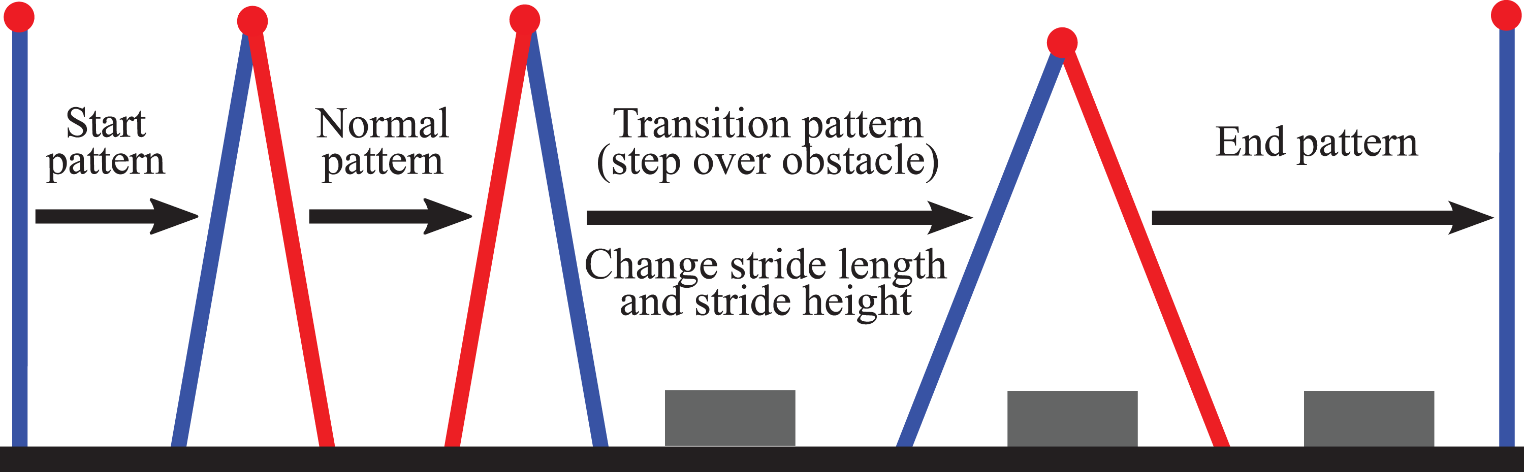
Four gait pattern diagram during walking. The blue line represents the right leg and the red line represents the left leg.
Sagittal balance based on linear inverted pendulum model
Nearly all bipedal robot walking gaits utilize highly bent knees, not only is this highly unnatural, it results in significant increase in power consumption at the knee compared to humans. 16 Therefore, the gait planning method of lower-limb exoskeleton robots cannot directly adopt the gait planning method of biped robots, and the gait of lower-limb exoskeleton robots must be human-like and straight-leg. Referring to the recent several excellent research on straight-leg walking of biped robots, 16,17 this article adopts the linear inverted pendulum model to ensure that the robot has certain stability and is human-like.
In a gait cycle, when double-support state turns to single-support state, the transfer of support point to one foot may lead to loss of balance. The stability of the linear inverted pendulum model can be evaluated by the phase diagram of the position and velocity of the center of mass. 18,19 The position of the hip joint is approximated as the center of mass of the body. The length of the pendulum is the length of the thigh plus the shank. According to the principle of the inverted pendulum, 20 the relationship between the horizontal position and the velocity of the body center of mass can be given as follows


where

Linear inverted pendulum: (a) Definitions of linear inverted pendulum model and (b) phase portrait of position x and velocity
Gait trajectory representation
It has been mentioned that the pendulum point of the inverted pendulum model can be used to represent the motion of the hip joint when the body’s center of mass is assumed to be in the position of the hip joint. This substitution is the basis of every gait pattern planning. In order to ensure that the exoskeleton robot can adapt to the complex environment, we hope that the exoskeleton robot can move accurately according to the desired path, which requires that the spatial position of the robot in motion can be known. Therefore, this article adopts the method of spatial position planning for the end of the robot, which can ensure that the end of the robot runs according to the specified spatial trajectory. However, to obtain the joint angle for motor control, inverse kinematics solution is needed, which may lead to the problem that the distance between the hip joint and the ankle joint is too large due to the unreasonable spatial position planning. So we should keep the motion law of the ankle joint and the hip joint in approximately synchronization and impose constraints so that the Euclidean distance between the ankle joint and the hip joint is less than the sum of thigh length and shank length. The spatial horizontal position of the hip joint can be expressed by formula (3), and the vertical position can be obtained by the following formula
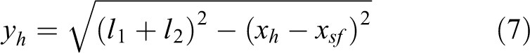
where yh is the vertical height of the hip joint, and
In this article, we use the pendulum point of the inverted pendulum model to represent the spatial position of the hip joint, and limit the length of the inverted pendulum to be unchanged, so the trajectory of the hip joint in a cycle is an arc, which means the slope at the initial and terminal moment is the largest and the slope is the smallest at the highest point. So the trajectory of ankle joint should follow this motion law. The standard sinusoidal function of half period is used to represent the spatial trajectory of ankle joint with the period of sinusoidal function is twice the stride length, the amplitude is the stride height, and the initial phase is 0. Moreover, we use the cubic function to represent the horizontal motion of the ankle joint, and limit the initial velocity of the ankle to be related to the initial velocity of the hip joint. The following formulas are used to represent the planning of the ankle of the swing leg

where

where x0 and
In the process of gait planning, the distance between ankle and hip joint is a constraint, it should always be less than the sum of thigh length and shank length. If this constraint is not satisfied, the coefficient α can be adjusted. After planning the spatial trajectory of the ankle and hip, the trajectory of the knee can be solved by constraints of the invariable leg length. There are two solutions to the position of the knee joint and the solution that makes the angle of the knee joint always be negative should be chosen.
Parameterized gait planning method
A complete gait planning process is that a decision system decides the gait pattern, stride length, and stride height of the next gait cycle of exoskeleton robot according to the actual environment information and tasks, then the gait planning method plans the next gait cycle according to the decision of the decision system. For example, if there is an obstacle in front of the robot, the sensor system will measure the distance and the size of the obstacle, while the decision system will make a decision about the information measured by the sensor system. The iteration strategies of decision system for next period of stride length and stride height are as follows


where LD is the distance between the obstacle and the ankle joint of the support leg.
The planning process of each pattern is consistent, but the initial state and the terminal state are different, as shown in Figure 3. To be able to plan dynamically, we parameterize the gait planning process as follows

where x0 represents the initial horizontal position of the robot center of mass relative to the support pivot.
Different gait patterns have different initial and terminal states, so their gait characteristics are different. Following are the expressions of the initial position x0, terminal position xf of the hip joint, and the forward distance L of the swinging ankle joint, which are used to calculate the spatial position trajectories of the hip and ankle joints through formulas (3), (6), (8), and (9).
Start pattern is the initial process of the whole movement, so there is no information about the previous step. The characteristics of this process can be described as

Normal pattern is defined as the motion process that does not change the previous step, so

Transition pattern is changed from initial stride length

End pattern is the final process of the whole movement. The characteristics of this process can be described as

As can be seen from the above definition, besides the start pattern, the definition of the initial position of the hip joint in other patterns is determined by the stride length of the previous step, that is, the initial state of the next step is the same as the terminal state of the previous step, which ensures the continuity and continuous transition of the planned gait.
Experiments
In practical application, gait data provided by planning method should be continuous and real time. Firstly, we run our planning method on MATLAB to verify whether the method can generate continuous gait trajectories, whether it can plan quickly, and whether the generated trajectories follow the human body’s motion rules to avoid harming users in practical application. Then, we will use an actual crossing obstacles experiment to verify the variability and adaptability of the proposed gait planning method.
Simulation experiments
In simulation experiments, the calculation time was evaluated by a computer with an Intel(R) Core(TM) i5-4210U CPU @ 2.40-GHz processor and 4 GB RAM.
The change of stride length occurs in the transition pattern, so the first step is to verify whether the transition pattern can generate a continuous trajectory that meets the requirement of stride length change. In the experiment, the stride length changed from 0.6 m to 0.4 m and 0.8 m. The controlled experiment does not change stride length, which means the new stride length is also 0.6 m. The average cost time for the whole planning is 0.8 ms. This shows that our planning method is fast and meets the real-time requirements. And we choose the angle trajectory of the left hip and the spatial position trajectory of the right ankle to compare. From Figure 5(b), we can see that the initial state of the three experiments is same at the beginning of the transition pattern. After the transition pattern, the absolute value of the angle of the left hip with smaller stride length is smaller than that of the invariable step, while the absolute value of the angle of the left hip with larger stride length is larger than that of the invariable step. Because for larger step, the distance between the feet is larger in double-support phrase, so the angle of the hip is also larger. For the step with smaller stride length, the distance between the feet is smaller in double-support phrase, so the angle of the hip is smaller. This shows that the data gained from our gait planning method is reasonable. And it can be seen intuitively in Figure 5(a) that when the stride length is changed, the horizontal position of the ankle will swing to the planned position after swing. And both the joint angle trajectory and the spatial position trajectory are continuous. What’s more, the angle of the hip joint ranges from −15° to 35°, which is within the range of clinical measurements. 21 These simulation results show that the proposed planning method can generate continuous gait data in real time, and these data conform to the human motion law. Other gait patterns does not need to change the stride length as the transitional pattern does, so we don’t make experiments of other patterns here.

Trajectories of transition pattern: (a) Spatial trajectories of right ankle and (b) joint angle trajectories of left hip.
Crossing obstacle experiment
We made a multisensor fusion of exoskeleton robot crossing obstacles experiment to evaluate the proposed planning method. In this experiment, robot need to adjust its gait in real time according to the environmental information provided by depth camera and the advanced intentions of the user provided by the brain–computer interface. It means that gait planning method must be able to quickly plan continuous and variable gait according to the information returned from the sensor system. Suppose there is a small obstacle (size: 21.5
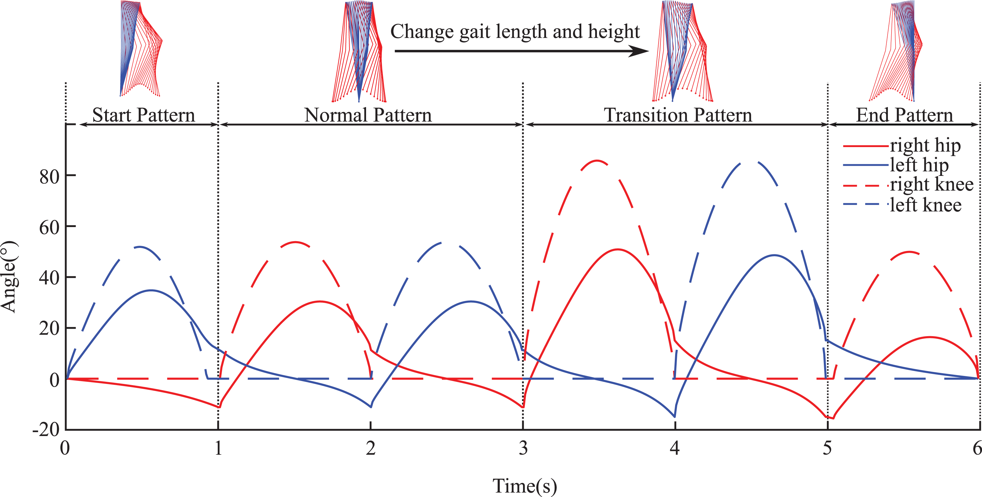
Joint angle trajectories during the whole process.

Spatial trajectories: (a) The spatial trajectory of hip and (b) the spatial trajectory of right ankle.

The actual experimental process diagram.
Conclusion
In this article, a fast parameterized gait planning method based on the inverted pendulum model is proposed. First, the walking process is divided into four gait patterns. Then, the inverted pendulum model is used to plan the spatial trajectory of hip joint and the sagittal balance of the robot is guaranteed by limiting the energy of the inverted pendulum. Finally, the planning process of the four different gait patterns is parameterized. The results of simulation experiments and crossing obstacle experiment demonstrated the proposed gait planning method can quickly generate continuous and variable gait trajectories of different gait pattern, which is also the basis for exoskeleton robots to adapt to complex environment. However, we adopt straight-leg walking and the orbit energy of the pendulum is positive, so the angular velocity of each joint is high at the moment when the double-support phrase changes to single-support phrase, which means the motor needs to have a high speed. Since gait planning process is parameterized, so that the gait planning process can be optimized according to some specific requirements (such as minimum energy consumption and the most similar to natural gait and other constraints). This is also our future work, exploring the optimal parameters under different constraints, and then determining the optimal trajectories.
Footnotes
Declaration of conflicting interests
The author(s) declared no potential conflicts of interest with respect to the research, authorship, and/or publication of this article.
Funding
The author(s) disclosed receipt of the following financial support for the research, authorship, and/or publication of this article: This work is partially supported by NSFC-Shenzhen Robotics Research Center Project (U1613219) and Open Project Foundation of Beijing Advanced Innovation Center for Intelligent Robots and Systems, Beijing Institute technology, Beijing, China (grant no. 2018IRS07).