
Abstract
Exoskeleton technology is more and more widely used in military, human rehabilitation, and other fields, but exoskeleton assisting mechanisms have problems such as high quality, concentrated driving sources, and poor flexibility. This article proposes a distributed variable stiffness joint power-assisted mechanism based on a laminated structure, which uses a giant magnetostrictive material as the driving source and the variable stiffness source of the structure. The distributed driving is realized by multiple driving units connected in series and parallel. Firstly, the drive unit stiffness matrix is deduced, and the expression equations of the cascaded total stiffness matrix of the drive module are obtained. After the simulation study, the curve of the stiffness of a single drive unit with a magnetic field and the stiffness of multiple drive units connected in series and parallel are in the absence of the magnetic field. The change curve of the stiffness of the booster module with the number of drive units under the excitation and saturation magnetic field excitation conditions is to achieve the effect of dynamically controlling the structural stiffness of the drive unit by controlling the size of the magnetic field and to obtain a general formula through data fitting. The number of drive units required under a fixed magnetic field excitation can ensure that the error is within 5%. The research results lay the foundation for further analysis of the distributed variable stiffness joint assist technology.
Introduction
At present, exoskeleton assist technology is used more and more widely in military and human rehabilitation treatment. Exoskeleton assist technology is usually driven by DC servo motor, hydraulic pressure, pneumatic pressure, flexible cable, and so on, all of which are centralized drive sources. The high stiffness characteristics of centralized drive source may cause harm to users, so the research of distributed and variable stiffness drive structure and method has also attracted the attention of scholars. 1 –5 Distributed drive structure is mainly used in scenarios where power transmission is difficult. Distributed drive makes the power assist mechanism more compact and can improve the drive efficiency and response speed. Variable stiffness is mainly used in various scenarios that need flexible mechanical structure, and it is the main measure to improve the flexibility of the power assist mechanism. The variable stiffness structure is easy for users to wear and reduces the harm of high stiffness to the human body. 6
Many scholars have reported the research on variable stiffness and distributed drive. Wang Jun of the University of the Chinese Academy of Sciences has researched variable-rigidity rope-driven joint modules. By connecting different numbers of variable-rigidity devices, variable speed drive in series, a single-degree-of-freedom, and two-degree-of-freedom rope-driven joint module with a wide range of stiffness variations has been obtained but failed to effectively change the stiffness performance test of the stiffness rope-driven joint module. 7 Ronald Van Ham et al. designed the robot Veronica by using the spring deformation direction to make a certain angle with the external force and adjusting the stiffness by adjusting the spring pretension, but the walking was not stable. 8 Harbin Institute of Technology Yike Shengli uses the Deutsches Zentrum für Luft-und Raumfahrt-Floating Spring Joint (DLR-FSJ) variable stiffness principle to achieve joint stiffness changes, but the structure is complex and the flexibility needs to be improved. 9 Metta 10 of the Italian Institute of Technology, etc. has designed a compact variable stiffness joint based on Series Elastic Actuation (SEA), but the number of motors required is large. Thirty-eight motors are required, only for the forearm of the Deutsches Zentrum für Luft-und Raumfahrt (DLR) arm system; the amount of data processing is large and the control is difficult. In recent years, flexible drives have become the focus of scholars’ research that has the characteristics of lightweight and good human-computer interaction. However, due to movement, skin slippage and other reasons caused by sensor offset, resulting in inaccurate control. 11 At present, distributed variable stiffness joint assist is still a big gap in research at home and abroad. Combining variable stiffness with distributed can not only increase the human–computer interaction flexibility of joint assist but also ensure its safety.
In this article, by introducing giant magnetostrictive materials and laminated structures, new variable stiffness and distributed driving principles are proposed. Combining the magnetostrictive material Terfenol-
Drive unit model
The driving unit proposed in this article is constructed with a laminated structure. The polyimide sheet is made into a specific shape according to the needs of constructing three degrees of freedom, from top to bottom are the upper drive layer, the upper excitation layer, the rotation layer, the channel layer, the lower excitation layer, and the lower drive layer. The structure and connection order of each layer is shown in Figure 1. Each layer is adhered to by DuPont Pyralux LF0100LF acrylic adhesive. Each synthesized drive unit has three degrees of freedom, from left to right are the first degree of freedom, the second degree of freedom, and the third degree of freedom. The action of the degrees of freedom is controlled by the giant magnetostrictive material, as shown in Figure 2. Magnetostrictive materials have the function of converting electromagnetic energy and mechanical energy, and their stiffness and shape will change under the excitation of the magnetic field. The energy density of giant magnetostrictive materials is higher. The magnetostrictive coefficient is larger, which is dozens of times of Fe and Ni, and three to five times of piezoelectric ceramics. 12 Therefore, giant magnetostrictive materials are used to design the joint assist mechanism.

Drive unit layer structure and connection order.

Drive unit degree of freedom.
Drive unit model working principle
The working principle of the drive unit model consists of two parts, one is the principle of variable stiffness and the other is the principle of the distributed drive. The variable stiffness principle guarantees the safety of the drive unit’s assistance; the distributed drive principle guarantees that each drive unit can be independently controlled to ensure the flexibility of its human–computer interaction. The two together works to achieve variable stiffness distributed joint assistance.
Variable stiffness principle
The magnetostrictive material Terfenol-
Input variable value.
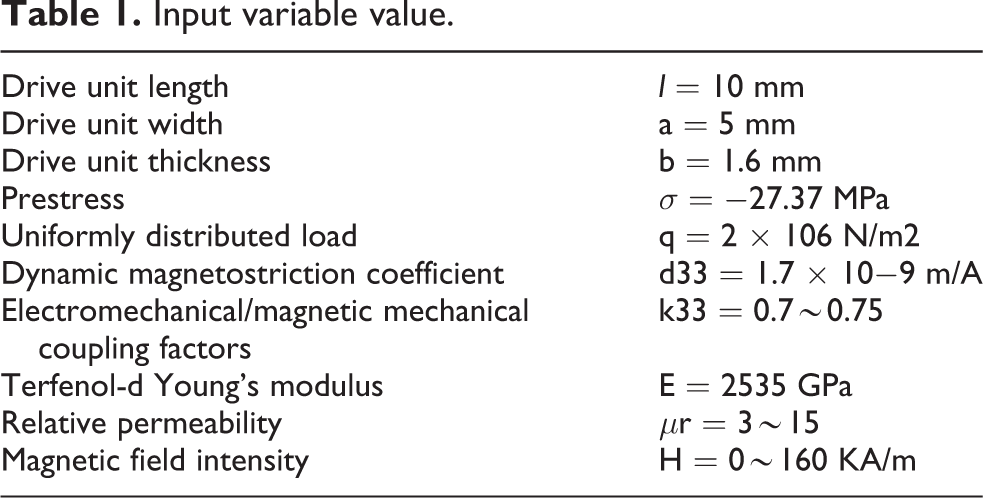


Among them,
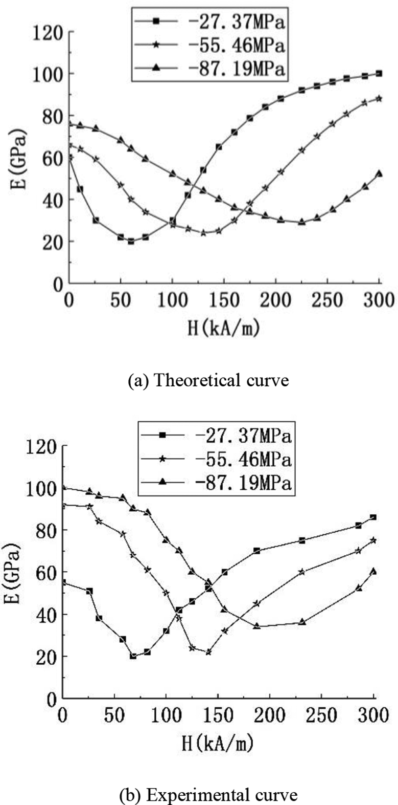
The variation curve of Young’s modulus under different pre-pressures at T = 20°. (a) Theoretical curve and (b) experimental curve.
Distributed drive principle
Distributed drive is an assist mechanism composed of n multiply by m drive units arranged in series. Each drive unit is connected in series or parallel by adhesion or tendon, but the excitation coil of each drive unit is powered separately, so each drive unit can control individually or combine multiple drive units into a regional stiffness module, and each area is individually powered to control the magnetic field to achieve a distributed drive effect of the area, as shown in Figure 4.

Drive unit distributed drive structure diagram.
Research on stiffness of distributed variable stiffness joint assist mechanism
Drive unit stiffness matrix
Two factors affecting the stiffness of the drive unit: one is the elastic modulus of the material of the drive unit, and the other is the structure of the drive unit. When a magnetic field is applied to a magnetostrictive material, the elastic modulus of the material becomes large, and at the same time, the structure of the drive unit changes due to the longitudinal magnetostriction of the magnetostrictive material, and the stiffness of the drive unit changes. Because the driving unit is small enough and only one end is fixed, the driving unit can be equivalent to a beam, and the stiffness matrix of the driving unit can be obtained by solving the stiffness matrix of the beam. The element has three nodes (degrees of freedom at both ends and degrees of freedom at the midpoint). The definition is introduced as follows


Each node of the driving unit has a


In the formula, i = 1,2,3. And M 1, M 2, and M 3 are the torques of the three planes xy, xz, and yz, respectively. That is, the force vector and displacement vector at the node of the driving unit are as follows


According to the theory of linear elasticity with small deformation, the effects of axial force Fx and bending forces Fy, F z , and M are independent of each other and there is no mutual coupling relationship, so the stiffness equation can be directly “assembled” by the stiffness equation of the axial force element and the plane bending element equation. The derivation and assembly of the stiffness matrix are mainly obtained through the assistance of MATLAB (https://www.mathworks.com/). It is used for data analysis and mathematical model derivation software. Its stiffness equation is as follows

where
Because the driving unit has three nodes, the stiffness matrices between 1,2 and 2,3 nodes are obtained first and then they are assembled into an overall stiffness matrix. The element stiffness matrix of spatial beam element in the local coordinate system is as follows

Among them, the bending stiffness coefficient


Then the assembly result of the overall stiffness matrix of the driving unit can be expressed by


Because the drive unit has a variable stiffness structure, the stiffness values under different magnetic field driving conditions are obtained through simulation and brought into the stiffness matrix, and the stiffness matrix results can be obtained.
The n drive units are connected in series, parallel, and series–parallel cascade to form a booster mechanism by bonding or tendons. The connection between the units will generate viscous damping c and viscous damping force

The physical properties of magnetostrictive materials are viscoelastic. The damping matrix can be expressed as

The mass matrix is obtained after the inertial force is equivalent to the static force of the node. Commonly used mass matrix representation methods include centralized mass matrix and consistent mass matrix. In this article, the element mass matrix is derived by the same method as the derived stiffness matrix, that is, the uniform element mass matrix is used. The solution method is similar to the element stiffness matrix solution, and each node has translational and rotational degrees of freedom, so it can be assumed that the diagonalized stiffness matrix is as follows

To sum up,

where 18 in
Simulation of stiffness of drive unit
The driving unit is equivalent to a beam, and the driving unit bears a uniform load during the boosting process. Therefore, the change in deflection of the beam can be used to represent the change in stiffness during simulation. First, the change of the deflection is obtained and then the change of the stiffness of the driving unit is calculated by the formula.
The A end is fixed and the B end is free, as shown in Figure 5. The stiffness matrix of the drive unit and the total force expression are obtained above. The specific relationship between the stiffness of the booster mechanism and the number of drive units can be obtained through simulation. It is more helpful to expand the booster mechanism. The z-axis stiffness value is examined to verify the feasibility of the variable stiffness booster mechanism.

Schematic diagram of equivalent cantilever beam of drive unit.
The equation of the curve around the beam under uniform load is given as follows

When x = l, the maximum deflection generated by the driving unit is as follows

where q represents the uniform load acting on the drive unit, l represents the length of the drive unit, and
To make the giant magnetostrictive material have a significant

The curve of
The above derivation was simulated and verified through analysis system (ANSYS) Workbench (https://www.ansys.com/). It is the collaborative simulation environment proposed by ANSYS, which can analyze the static mechanics, dynamics, electromagnetic field, and coupling field of complex mechanical systems. When no magnetic field excitation and different intensity magnetic field excitation were applied, a surface force of

Young’s modulus of the drive unit with the magnetic field strength curve when the pre-pressure is
According to the above figure, it can be seen that the stiffness value of the drive unit changes significantly when the magnetic field is not excited and after the saturated magnetic field is excited. By comparison, it can be concluded that the stiffness of the drive unit has increased by 808.1%. According to the curve, the curve can be divided into three sections: the magnetic field is from nothing, the magnetic field is from small to 75 KA/m, and the magnetic field is from 75 KA/m to the saturated magnetic field.
The drive unit can be applied to different working situations according to the three situations. The magnetic field has a rapid change in stiffness from none to sometimes, which can be applied to the moment when the human muscle has a strong explosive force; the magnetic field gradually decreases from a small magnetic field to a period during which the stiffness can be reduced, During the deceleration phase of human muscles, the magnetic field is from 75 KA/m to a saturated magnetic field, and the stiffness of the drive unit slowly increases, which can be applied to the lifting phase of the human body carrying heavy objects. According to the analysis above, it is found that the drive unit can achieve variable stiffness under the action of the excitation magnetic field and meet the design requirements.
Stiffness characteristics of distributed power-assisted mechanism
Combined with the derivation of the stiffness characteristics of the single drive unit above to study the stiffness of the distributed booster mechanism, there are seven cases of distributed drive expansion: x-direction one-dimensional expansion; y-direction one-dimensional expansion; z-direction one-dimensional expansion; x, y-direction two-dimensional expansion; x, z two-dimensional expansion; y, z two-dimensional expansion; and x, y, z three-dimensional expansion. Take three typical situations of the seven expansion methods for simulation research: the drive unit z expands in one dimension, the drive unit x expands in one dimension, and the drive unit expands in two directions in x and y. The relationship between the stiffness of the extended drive module and the number of drive units connected in series and through simulation is obtained through simulation. A general formula for the stiffness and the number of drive units is obtained by data fitting. The formula can be used to inverse the number of drive units required when different stiffness is required.

Schematic diagram of three typical expansion modes of drive unit. (a) Z-direction one-dimensional extended of drive unit, (b) X-direction one-dimensional extended of drive unit, and (c) Schematic diagram of two-dimensional drive.
When the stiffness of the single-layer drive unit cannot meet the requirements, multiple drive units can be connected in parallel in the z-direction. The way is to glue the upper drive layer of the lower drive unit and the lower drive layer of the upper drive unit together with DuPont acrylic adhesive. And when the drive module is placed at a joint such as an arm to assist, the boost area of a single drive unit is far from meeting the needs, so the drive units need to be connected in series or two-dimensional spread to a large-area series booster mechanism. The connection method is the rear face of the previous drive unit bond or adds tendons to the front face of the latter drive unit for connection.
Compare the change in the stiffness of the booster mechanism with and without magnetic field excitation and obtain the z-direction displacement through the probe, that is, the deflection value of the parallel booster. The relationship between the number of drive units and the deflection value under three typical expansion modes is presented in Table 2.
Deflection values of different number of driving units under three typical expansion modes.

The relationship between the deflection and the number of units under the conditions of z-direction one-dimensional extended of the drive unit can be obtained by fitting the curve data as follows


According to Equation 26, it can be found that when there is only one driving unit, the error between the brought-in function and the simulation data is large. When
When the saturated magnetic field excitation is applied, according to Equation 27, it can be found that this fitting function is suitable for any number of parallel drive units, and the error is guaranteed to be within 5%. According to this relationship, the variable rigidity of the power-assisted mechanism can be calculated when multiple drive units are connected in parallel without excitation magnetic field or saturated magnetic field in the later period, and the number of parallel drive units required can be reversely derived through variable stiffness requirements.
By fitting the curve data, the relationship between the deflection and the number of units under the conditions of x-direction one-dimensional extended of the drive unit and Schematic diagram of the two-dimensional drive is as follows


According to the fitted function, it can be found that this fitting function applies to the serial number of any driving unit, and the error is guaranteed within 5%. According to this relationship, the variable stiffness of the drive module can be calculated when multiple drive units are connected in series and series–parallel combination without excitation magnetic field or saturated magnetic field in the later period, and the required number of series drive units can be reversely derived through variable stiffness requirements.
By analyzing the combination of the driving unit z in one dimension and x in one dimension and driving elements in two directions x and y, the general relationship between the change in deflection and the number of series and parallel connections can be obtained. According to Equation 21, the change of the assist mechanism
Verification
Verification of arm movement assistance
When the human forearm supports a heavy object, the forearm stays fixed near the shoulder end. The forearm pulls due to the contraction of the biceps brachii of the forearm.

Assistance mode diagram.
The average length of the upper arm and the lower arm is 328 mm and 312.8 mm, respectively, and the muscle strength is normal five-grade muscle strength. 14 The biological structure of arm muscles is complex, and the Anybody (https://www.anybodytech.com/) software platform can be used to build the skeleton and muscle groups of the human arm and accurately monitor the changes in muscle strength of the major muscles of the arm. It is a computer-assisted human ergonomics and biomechanical analysis software, both ergonomics and biomechanics to calculate the body’s biomechanical response to the environment. To reduce the amount of software calculation, the mechanics of the arm is simplified. Finally, the arm is simplified as shown in Figure 10. When the human body lifts a heavy object, the deltoid muscle forces and keeps fixed, and the forearm flexes and extends in the sagittal plane of the human body due to the contraction or relaxation of the biceps, The right arm in the figure is simplified to the left model, including the upper arm and the lower arm, and the main muscle groups are the deltoid, biceps, triceps, and brachioradialis.

Arm simplified model, 1-Deltoid, 2-upper arm, 3-biceps, 4-triceps, 5-brachioradialis, 6-tendon, and 7-lower arm.
The driving unit is shown in Figure 11 and it is composed of polyimide sheet and Terfenol-

Prototype drawing of driving unit.
The driving unit is cascaded into strip and sheet assisting mechanisms according to the length of the arm and is clung to the backside of the arm through the bandage. To improve the effect of the booster mechanism, a number of sheet booster mechanisms are wrapped around the arm to form a ring booster mechanism, which is pasted on the tight elbow protector and closely attached to the arm. Schematic diagram of each type of mechanism is shown in Figure 12.

Schematic diagram of various types of power assist mechanism. (a) Motion diagram, (b) stripe assist mechanism, (c) sheet assist mechanism (d) ring-shaped assist mechanism.
Changes in arm muscle strength
During the kinematics calculation of the simplified arm model, the shoulder node was taken as the origin of the model coordinate system, the gravity of 10 kg weight was added to the hand node, and the upward bending arm movement was defined. The motion angle is 90° and the motion time is 1 s. A new node is defined at the corresponding position of the arm model according to the schematic diagram, and the stiffness and disturbance formulas of each type of assist mechanism are defined in the node parameters. Muscle strength analysis was carried out under the condition of no magnetic excitation (0 kA/m) and magnetic excitation (160 kA/m), and the data of the change of muscle strength Fm with time in the process of exercise were obtained. The parameters of the components of the assist mechanism are presented in Table 3.
Material parameter sheet.

Simulation parameters, load conditions, and boundary conditions of each type of assist mechanism are the same. After validated analysis, the maximum muscle force of the muscle can be obtained through data processing, as presented in Table 4.
Table of maximum muscle force and reduction rate of each type of assist mechanism with or without magnetic excitation.

When there is no magnetic field excitation, the main muscle force of arm flexion movement is provided by biceps and deltoid muscles, while the other muscle groups are in a diastolic state. By comparison, it is found that the average muscle force of the strip-assisted mechanism is reduced by 9.2% under the saturation magnetic field drive, and the assistance mechanism plays a small role. Driven by the saturated magnetic field, the average muscle strength of the plate-assisted mechanism is reduced by 27.5%, which plays a good role.
According to the data in the table, it can be found that when the stiffness of the annular assist mechanism changes significantly with or without magnetic excitation, the assisting effect of the joint is significantly different. The comparison results showed that in the absence of magnetic excitation, wearing the annular assist mechanism would cause a certain burden on the arms curvature, and the muscle strength was larger than that of strip and sheet. However, driven by the saturated magnetic field, the average muscle strength decreases by 57.9%, which plays an excellent helping role, which proves that the ring assist mechanism has an obvious helping effect and high feasibility.
The variation of the arm’s load capacity was analyzed with the magnetic field intensity and the load capacity of the arm was reversely calculated under the stress value when the magnetic field intensity is different. The changing curve of arm load capacity with different intensity magnetic field excitation of the assisting mechanism is shown in Figure 13.

Change curve of arm load capacity.
With the change of the magnetic field, the stiffness value of the booster mechanism changes and the magnetic field intensity in the range of 0 < H <60 KA/m; When the stiffness value reaches the lowest near 60 KA/m, the effect is the least. The stiffness value of the assist mechanism reaches the maximum near the saturated magnetic field (160 KA/m), which has the best effect on reducing the muscle strength.
The initial load of the arm is 10 kg, and the load becomes 11.45 kg with an annular assist mechanism without magnetic field excitation, and the load capacity is 30.15 kg with saturated magnetic field excitation. According to the graph, the annular assist mechanism plays an important role in improving the load capacity of the arm.
Conclusion
This article assists the mechanism in modeling and principle analysis, derives the stiffness matrix of the drive unit, and simulates and verifies the drive unit’s three different expansion modes. Finally, the simulation validates the effect of the booster mechanism on the improvement of the human skeleton stiffness. The main conclusions are as follows: (1) the derived stiffness matrix of the driving unit satisfies the characteristics of the element stiffness matrix, which proves that the derivation is correct; (2) the simulation and verification of the three typical expansion modes of stiffness and the number of driving units and data simulation. The general formula of the relationship between the two can guarantee that the error is within 5%; and (3) through the simulation of human body assisting simulation, it is verified that the assisting mechanism can meet the assisting requirements, the assisting effect is obvious, and the excitation magnetic field with different strengths can be adjusted to meet the requirements according to the stiffness requirements. However, the interference of the excitation electromagnetic field with the peripheral electronic equipment is not considered, and further research is needed. The study of distributed variable stiffness joint assist in this article provides a reference value for further research on the human exoskeleton.
Footnotes
Declaration of conflicting interests
The author(s) declared no potential conflicts of interest with respect to the research, authorship, and/or publication of this article.
Funding
The author(s) disclosed the receipt of the following financial support for the research, authorship, and/or publication of this article: This study is supported by Jiangsu University, department of education of Liaoning Province and National Natural Science Foundation of China.