
Abstract
In this paper, a continuously variable stiffness control strategy for shaft-hole assembly with a compliant wrist is proposed. The compliant wrist adjusts stiffness by changing the cantilever length of a super-elastic Ni-Ti wire. Its core idea is that when the contact force of the robot exceeds a particular value, the wrist adjusts the stiffness and can deform in a specific direction that guarantees assembly, allows a relatively significant misalignment, and produces a small force. The advantage of the proposed strategy is that the shaft-hole assembly status is supervised by calculating the deformation of compliant wrist based on contact force information, this significantly decrease the requirements of shaft-hole alignment accuracy. On this basis, the kinetostatic coupling kinematic and static force model is built and the fuzzy PD stiffness control strategy is designed to realize the desired stiffness of the wrist in various directions. Finally, the shaft-hole assembly experiments under different misalignment error demonstrates the reliability of the wrist, indicating the efficacy of the control method.
Introduction
The manipulator has been widely applied in the field of assembly process in automatic factory. 1 However, many confounding factors impinge upon the assembly process as robots interact with their environments. The robot itself cannot accurately identify the contact status.2–3 Even minimal errors in the assembly process may cause assembly failure or damage to the assembly parts or robots. Additionally, with the acceleration of product development cycles, there are a greater number of assembly parts, especially in the assembly process of complex equipment. The stiffness and position information of the parts is usually incomplete and inaccurate, which brings potential risks to the robot in the process of rigid interactive operation. Therefore, the development of a compliant operation robot is of great interest.
In general, an interaction force will occur between the robot and its environment. Therefore, our research focuses on how to regulate the robot’s environmental interaction. The researcher addresses the main problem in the process of shaft-hole assembly and conducts a study on the robot’s compliance, which refers to the robot’s ability to show some adaptability to an unknown environment to assist in completing the assembly. There are two approaches to compliant assembly, passive and active compliance. Many studies have used active compliance control strategies to improve assembly performance. These active compliance control methods include stiffness control, 3 impedance control, 4 and hybrid F/P (force/position) control. 5 These studies mainly focused on two aspects: impedance control and hybrid F/P control. Impedance control methods include adaptive neural network, 6 adaptive, 7 adaptive learning, 8 variable-stiffness 9 and robust adaptive impedance control. 10 The force/position control includes hybrid, 11 adaptive, 12 robust, 13 neural network, 14 and learning F/P control. 15 Although these methods can achieve compliance control with the dynamic model of the manipulator, it is costly and complex, and the control algorithm relies on an accurate dynamic model of the manipulator, making it difficult to achieve the desired universal suppleness of function. Therefore, research has carried out on low-cost, more adaptable passive compliance devices.
In contrast to active suppleness, passive suppleness control is achieved by loading some additional auxiliary mechanism, such as a spring mechanism, at the end of the robot so that it can produce some compliance when it comes in contact with the environment. The compliant behavior is achieved through the interaction between the wrist and the contact object. Passive compliance effectively separates force control from the robot controller by introducing a compliant device independent of the robot. The interaction between the robot and the environment was realized by changing the stiffness of the contact point. It is feasible to design specific mechanical structures to achieve the robot’s weak or constant force control to contact the environment. For example, Seungjoon 16 designed the RCC (remote center compensation) structure to the passive compliance device and a robust industrial robotic assembly process is achieved. However, the compliant center of the RCC device is difficult to adjust, resulting in poor adaptability and versatility to different stiffness. SRCC (Spatial remote center compliance) introduces an additional axial rotation for accommodating the prismatic peg components. 17 An HRCC (horizontal remote center compliance) reduces the insertion force and avoids the jamming conditions in the dynamic insertion of chamfer-less peg-in-hole assembly along with horizontal and vertical directions.18–19 VRCC (Variable remote center compliance) with stacks of elastomer shear pads and shear controller changes the compliance center concerning the insertion depth. 20 Sangcheol and Liu21,22 used the spring mechanism and the compliant linkage mechanism to realize passive precision assembly, respectively. Chen 23 introduced an end pneumatic compliance mechanism to ensure compliance with the environment by controlling the input gas pressure. The above-mentioned passive compliant devices consider the assembly of a shaft-hole in a quasi-static situation, but the actual assembly process is dynamic. Therefore, several auxiliary sensors are used to assist with the dynamic assembly process, including vision and force sensors, to improve assembly precision. For example, Huang 24 proposed a robust control method based on visual information. In paper, 25 a robust passive control method based on visual information for the assembly task is proposed in the presence of attitude alignment errors. However, the stiffness of the contact tip cannot be dynamically adjusted.
From the discussion above, active compliance firstly requires precise identification of the contact environment, high requirements for force sensor accuracy, and complex control algorithms. Errors can produce an enormous impact, resulting in jamming, wedging, or surface damage. Secondly, passive compliance entirely relies on its fixed stiffness and lack of active adaptation to complex environments, which restricts its application in practical production. Therefore, if the advantage of two compliant methods can be combined, the robot can exhibit ideal compliant characteristics while reducing control difficulties and achieving high-precision assembly.
A continuous variable-stiffness wrist is used to achieve composite compliant operation, leveraging the advantages of both active and passive compliant approaches. The rigid robot can provide an accurate position with limited dependence, while a compliant wrist can effectively regulate and offset the forces exerted by the environment. The wrist is based on the Cosserat rod model and combines the characteristics of active and passive suppleness, which can continuously change the wrist stiffness according to the assembly interaction force. The wrist stiffness matches the stiffness of the acting object. Based on this, a stiffness controller with a fuzzy PD control method is designed to realize the desired stiffness of the end tip in various directions by adjusting the position of the slider. The wrist has the following features: 1) the tip stiffness is numerically obtained by solving the equations of the Cosserat rod theory. 2) the stiffness of the wrist can be adjusted continuously according to contact force. 3) the contact force is used as a means to determine the stiffness. 4) The proposed control strategy converts the stiffness control into the position control of the screw slider of the wrist.
Description of the compliant wrist
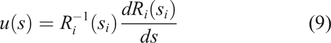
Assembly efficiency can be improved by adjusting the stiffness of parts during assembly to make sure the contact force satisfies the requirements. However, when the contact force exceeds a given value due to a relatively large misalignment, damage to the shaft and hole can be avoided by reducing the stiffness of the operation tool. These cases require the operation tool to have a variable stiffness during assembly. Here, a variable stiffness compliant wrist is used to realize variable stiffness performance to reduce contact force, as shown in Figure 1 (a) Structure of complaint assemble system; (b) structure of wrist; (c) Variable-stiffness mechanism; (d) Structure diagram of wrist.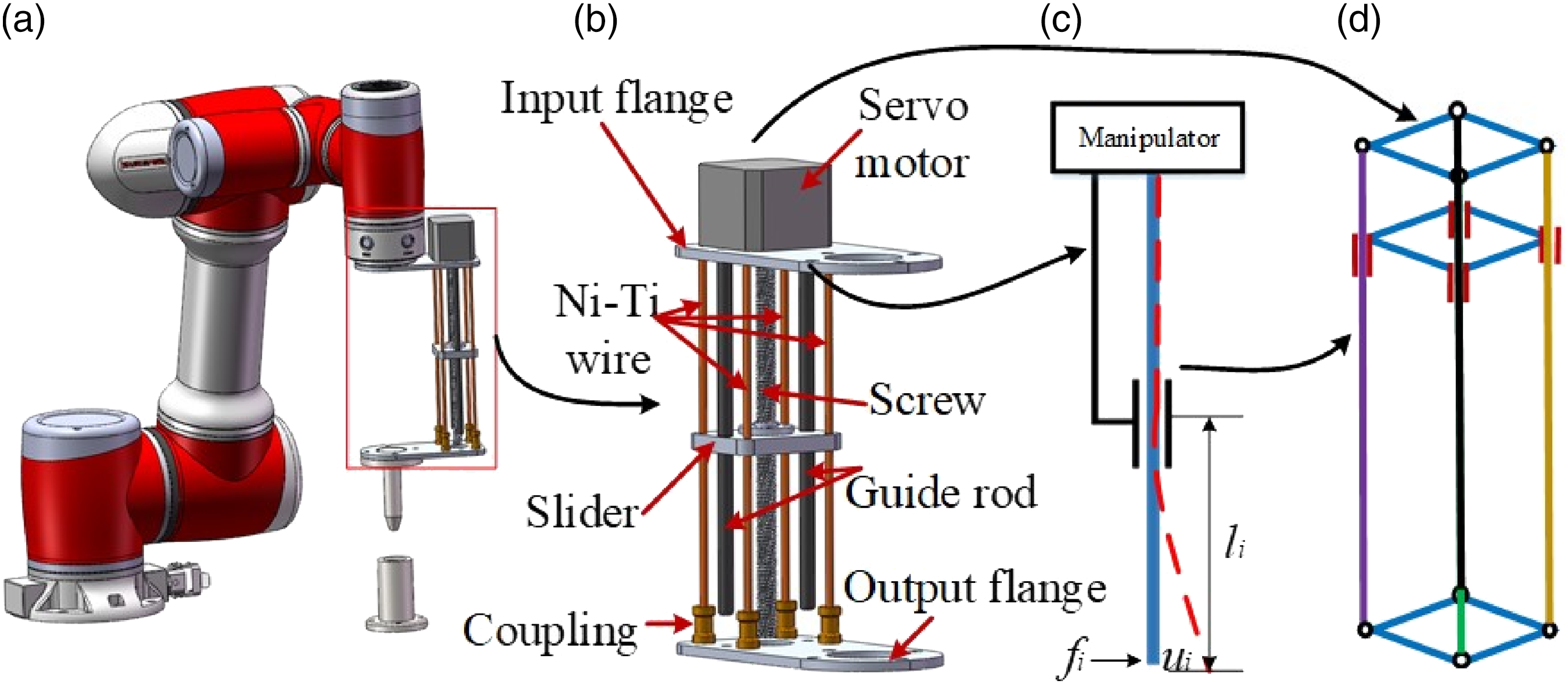
The compliant wrist consists of four hyper-elastic Ni-Ti alloy wires, two guide rods, one screw, one slider, and one servo actuator. The guide rods and the screw are rigid and the only connection with the robot. The four Ni-Ti alloy wires are flexible to connect the robot and the assembled shaft. The servo actuator drives the slider. The rigidity of the guide rods and screw cause the upper portion of the slider to be rigid and the lower portion to be flexible. This flexibility changes with the position of the slider.
Due to the use of Ni-Ti alloy wire, the wrist experiences elastic recoverable deformation, as shown in Figure 2. When the slider moves along the axial direction of the Ni-Ti wire, the length of the cantilever changes under the deformation principle diagram of the Ni-Ti wire. The screw-slider mechanism is used to adjust the extension length of the Ni-Ti alloy wire (a) The deformation along x and y-axis under the force 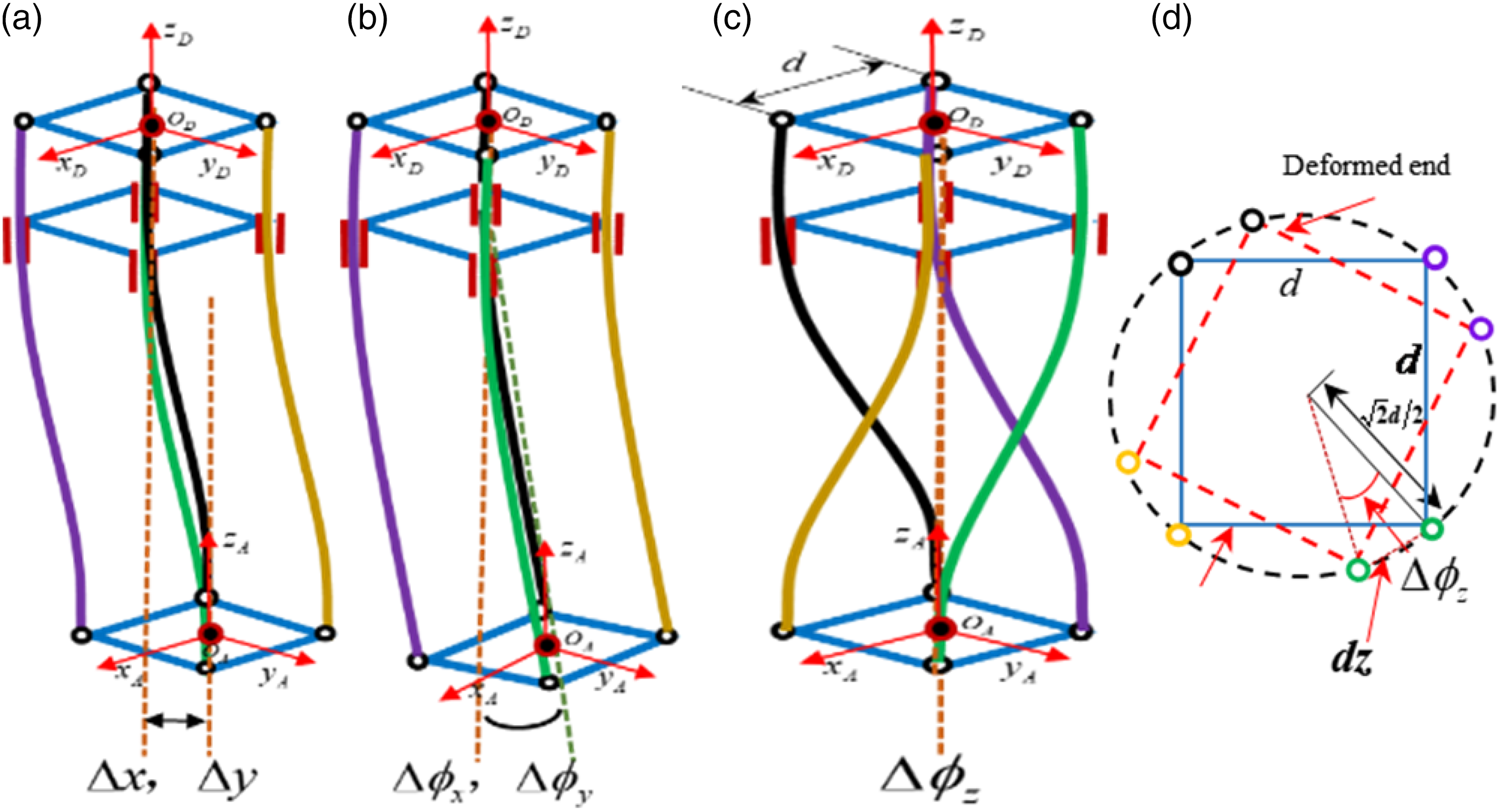
Once the contact force acts on the end of the wrist, the wrist will produce transverse deformation along x and y-axis, rotational deformation around z-axis to avoid force overshoots.
The force acting on the tip of the Ni-Ti wire is set as
Thus, once the contact force
The robot assembly system contains a 6-DOF manipulator, compliant wrist, and force sensor and control system, as shown in Figure 3. During insertion, the deformation and stiffness of the wrist are dependent on the horizontal offset error and contact force. Compliant robot system.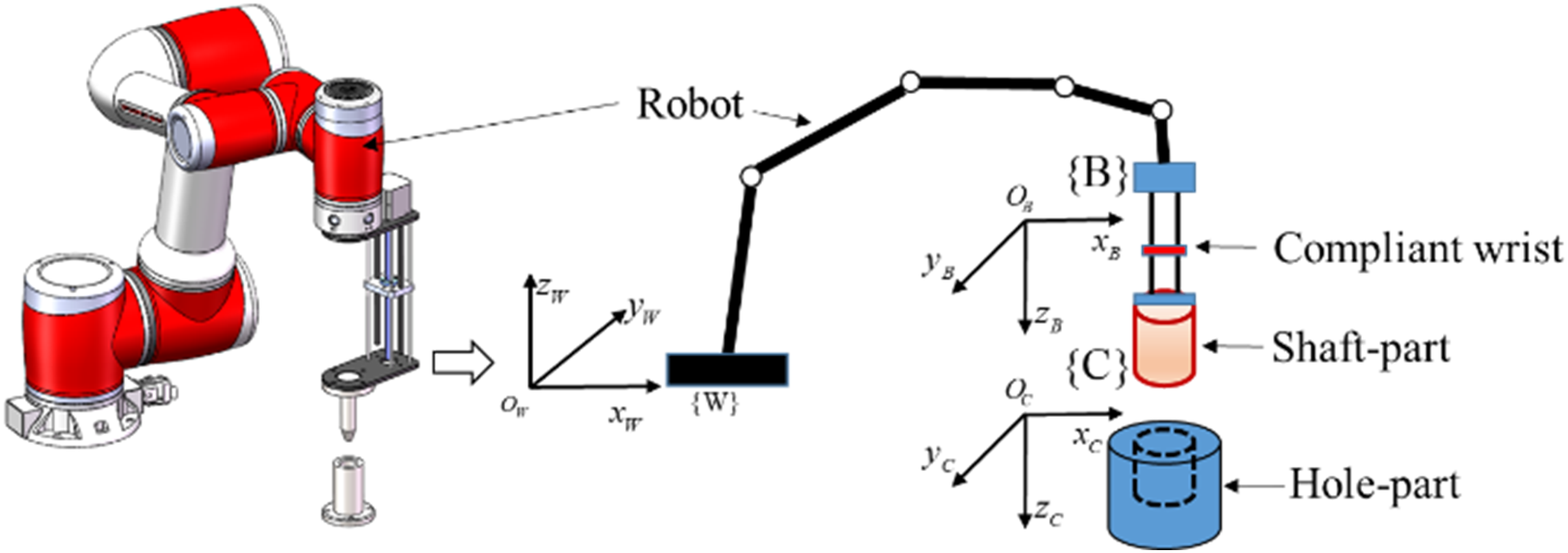
Kinematic and force mapping
Shown as in Figure 4, Structure diagram of the compliant robot system.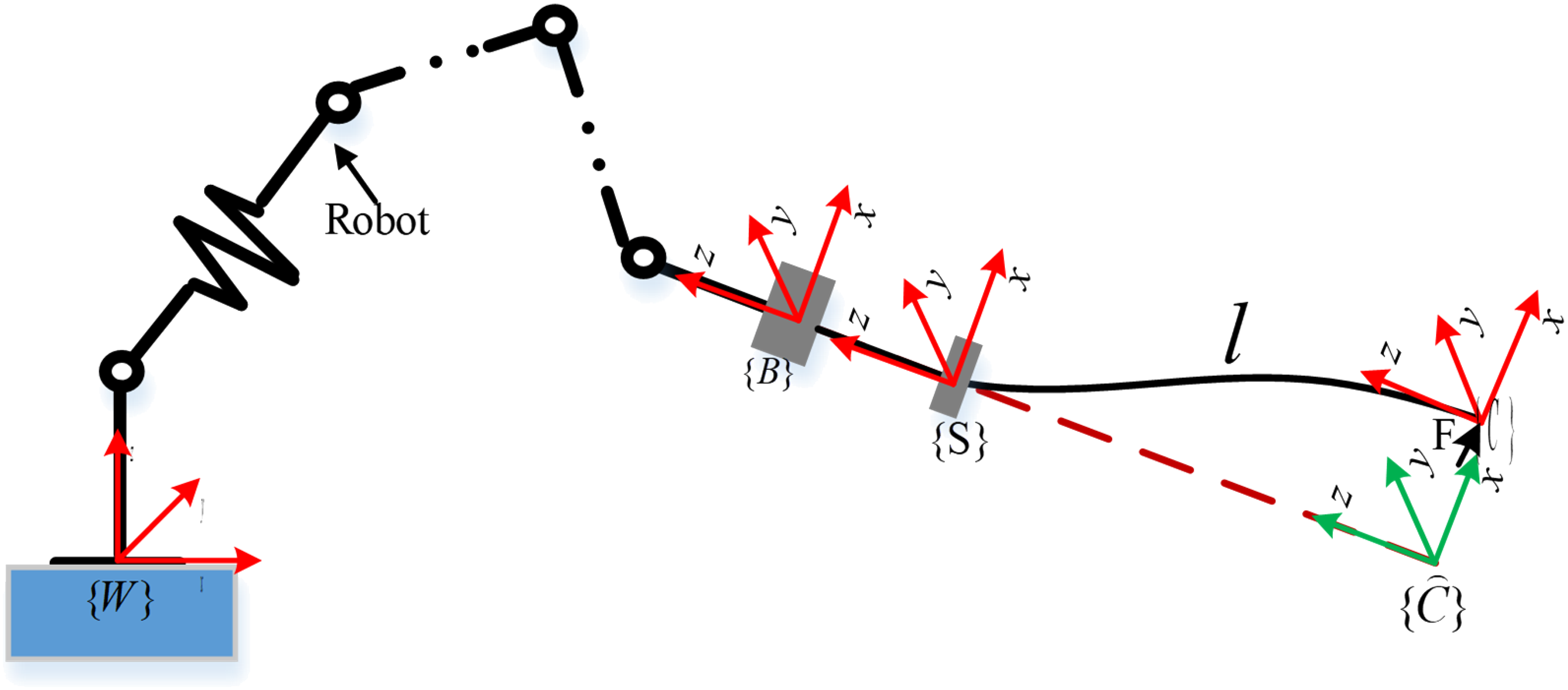
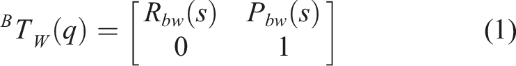
The transformation matrix between coordinate system
Refers Figure 5, the transformation matrix between coordinate system Deformation of a single Ni-Ti wire with force vector 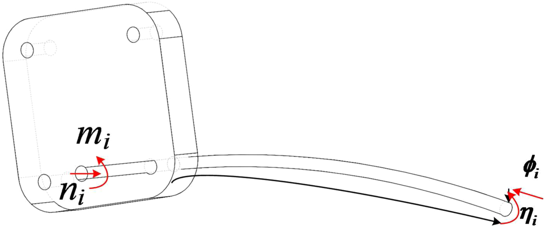

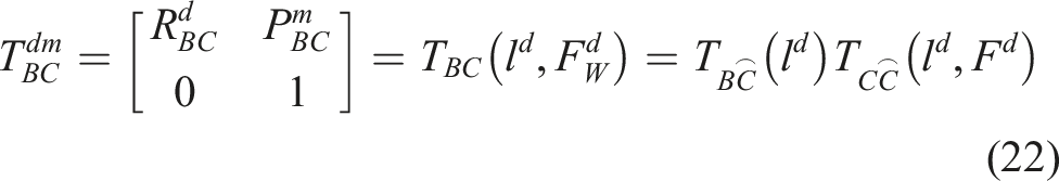
Therefore, the transformation matrix
The product
Based on the virtual work principle, the force mapping can be obtained
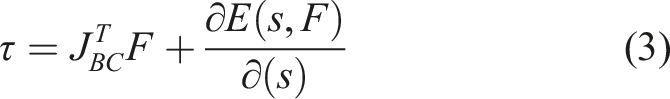
In general, when the wrist is in a rigid state, the equation can be rewritten as
Kinestostaic modelliing
To obtain the product
When the tip force vector causes significant relative displacement between the elastic components of the wrist, several Cosserat rods can calculate the deviation deformation. 27
Modelling of single Ni-Ti wire
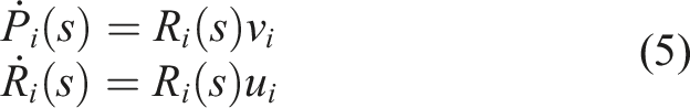
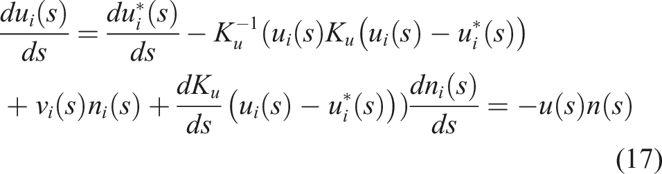
A wrist consist of four Ni-Ti wires, the shape of the i-th Ni-Ti wire is defined by its position

The differential of equation (4) is
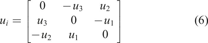
In which,
Then, the deformation can be presented as
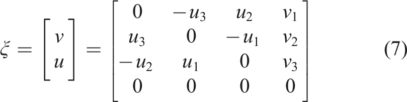
Therefore, if the vectors
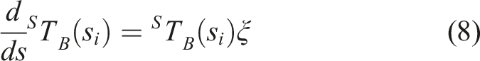
Thus, the differential of
The shape of wrist deflection with no load can be computed as follows
Refers paper,
28
the internal force vector
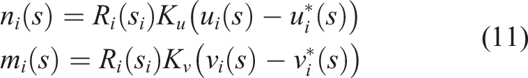
The relationship between internal force vector and acting force vector is as follows.
Kinetostatic modeling with contact loads
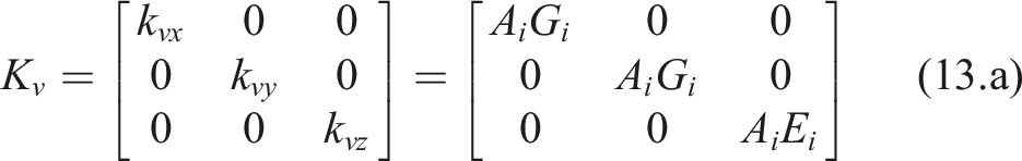
The constitutive model that relates strains
We defined the initial position of Ni-Ti wire without loads as
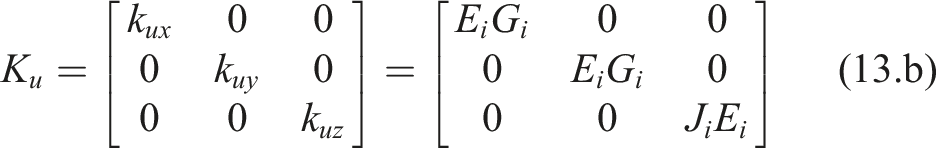
Combining equations (10)–(12), we get the kinestostaic model of the Ni-Ti wire.
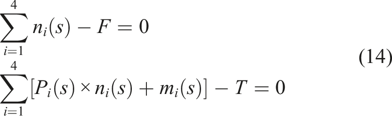
Ignoring the type of mechanical connection of the Ni-Ti wire to the output flange, the static equilibrium about all forces and moments is as follows.
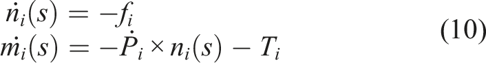
Based on the Cosserat rod model [30], the differential equation of moment m and force n about s is as follows.
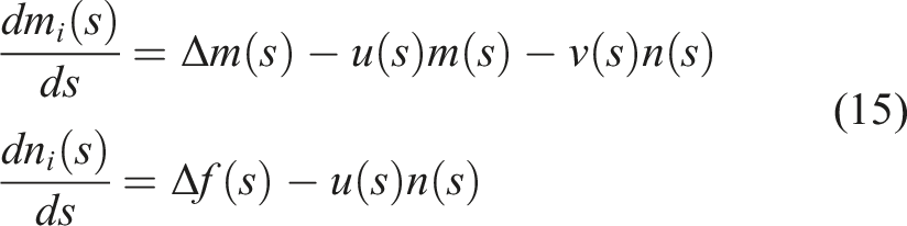
Combing equations (10) and (14), the equation for
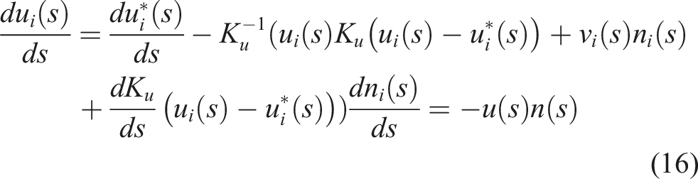
Therefore, the force vector
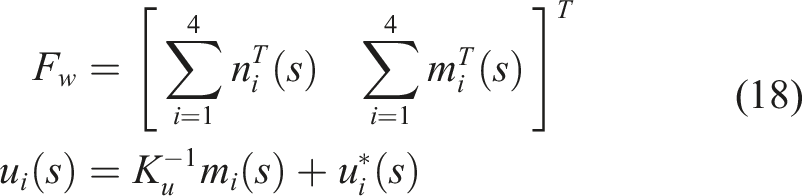
The desired end tip wrench
The inverse kinematic of the wrist corresponding to the position of the slider is

Therefore, we can get the end deformation position of the wrist caused by the force vector.
Design of fuzzy PD controller and stability analysis
Design of fuzzy PD controller
During the shaft-hole assembly process, the contact force changes rapidly, and the control of stiffness is exceedingly complicated. In this section, a stiffness controller is designed for the compliant robot system to adjust the contact tip stiffness, which aims to promote the compliance control performance during the assembly process. Simultaneously, the fuzzy PD (Proportional-Derivative) control strategy is used to improve the stiffness control performance in the contact force control loop.
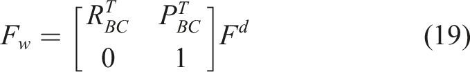
The desired force acting on the tip of wrist is

The desired force
According to (19), ones have
To control the stiffness, we convert from the stiffness control into position control of the wrist by using the PD control algorithm. Then, the diagram of stiffness control is shown in Figure 6. The actual tip position and desired position are used to calculate stiffness and control the movement of the screw-slider, then, the cantilever length of the Ni-Ti wire varied with the change of stiffness. Therefore, the end stiffness of the robot system can be controlled by feed-forward feedback to the fuzzy PD controller. Diagram of stiffness control.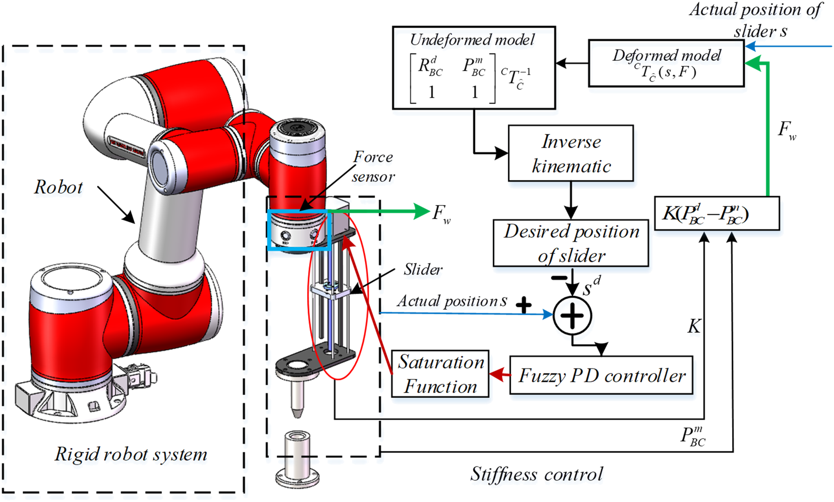
The traditional PD control method is

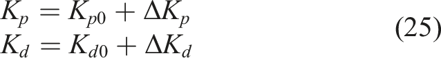
The key point of fuzzy PD control is to optimize the two control parameters of the PD control system with fuzzy control theory. The two control parameters
Fuzzy rule base of
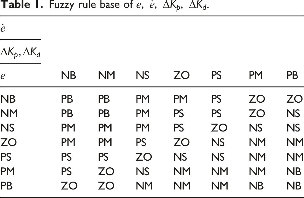
The range of
The parameters 

Then, the fuzzy base domain of 
A saturation sigmoid function is used to limit the range of output stiffness once the expected stiffness exceeds the allowed range. Then, the input of control is
Stability analysis
To guarantee the stability and providing a robust stiffness control performance of the proposed controller, the stiffness control is reflected on the force control. The force control loop is simplified to complete the analysis of stability and calculation of steady-state error. The force control loop is illustrated as Figure 7, here Simplified contact force with stiffness control loop.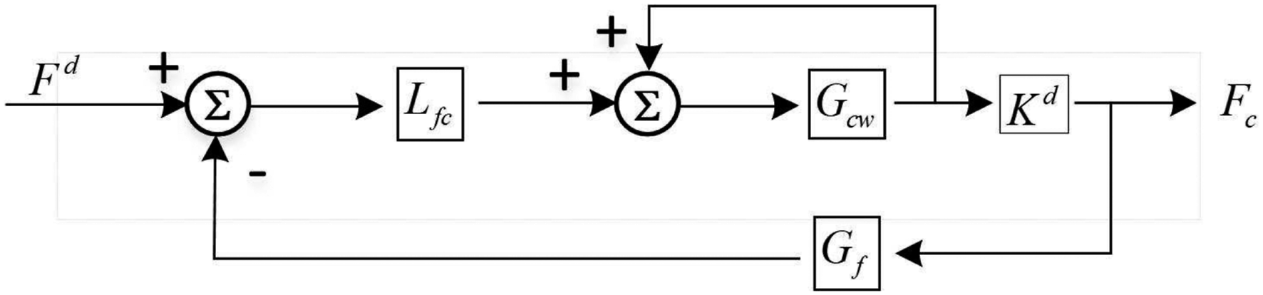
Thus, 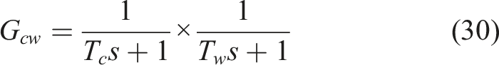
And (a) Robot assemble system; (b) the compliant wrist.
According to the Routh criterion, the stability condition of the fuzzy PD control system is represented as
Therefore, the stability of the control system is
From above, the system control error is
The system stability error is
In general, the control input signals of compliant wrist is pulse signal, it means 
Therefore, according to the Routh criterion, the contact force with stiffness control is stable.
Experiment verification and analysis
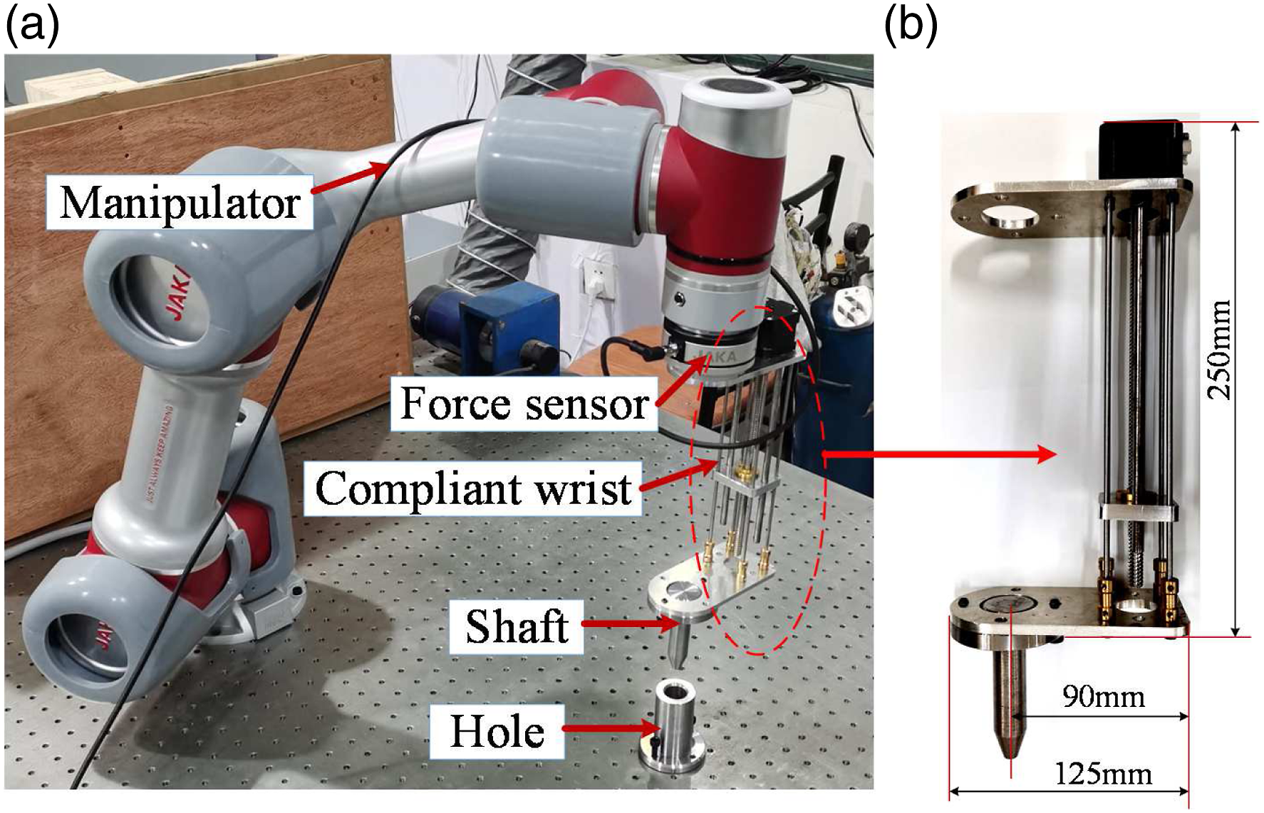
In this section, the compliant wrist is applied to connect the manipulator and the gripper (parts). A JAKA manipulator with the Advantech 610L PC and a force/torque sensor are used as the manipulator. The assembled system is shown in Figure 8(a), and the shape parameters of the compliant wrist are illustrated in Figure 8(b).
Simulation
Based on the above, a stiffness tracking control simulation is carried out with the input stiffness defined as:
Simulation of stiffness tracking and tracking error shown as in Figure 9. Results shows that the fuzzy PD controller can effectively realize the tracking of the contact stiffness between parts. (a) Stiffness tracking control; (b) tracking error.
Experiment verification
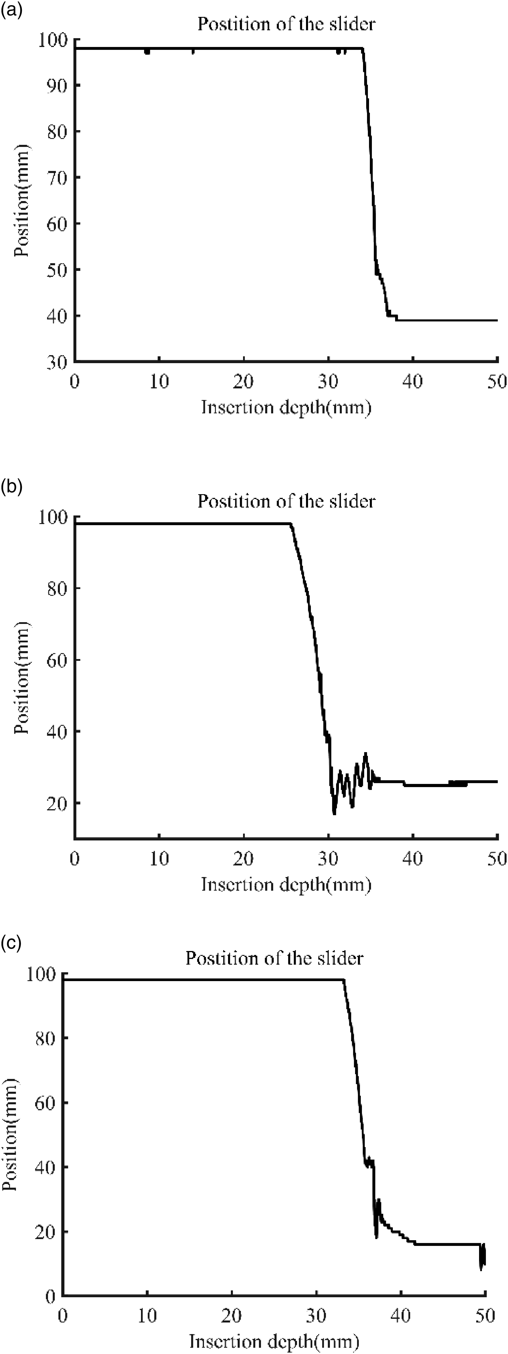
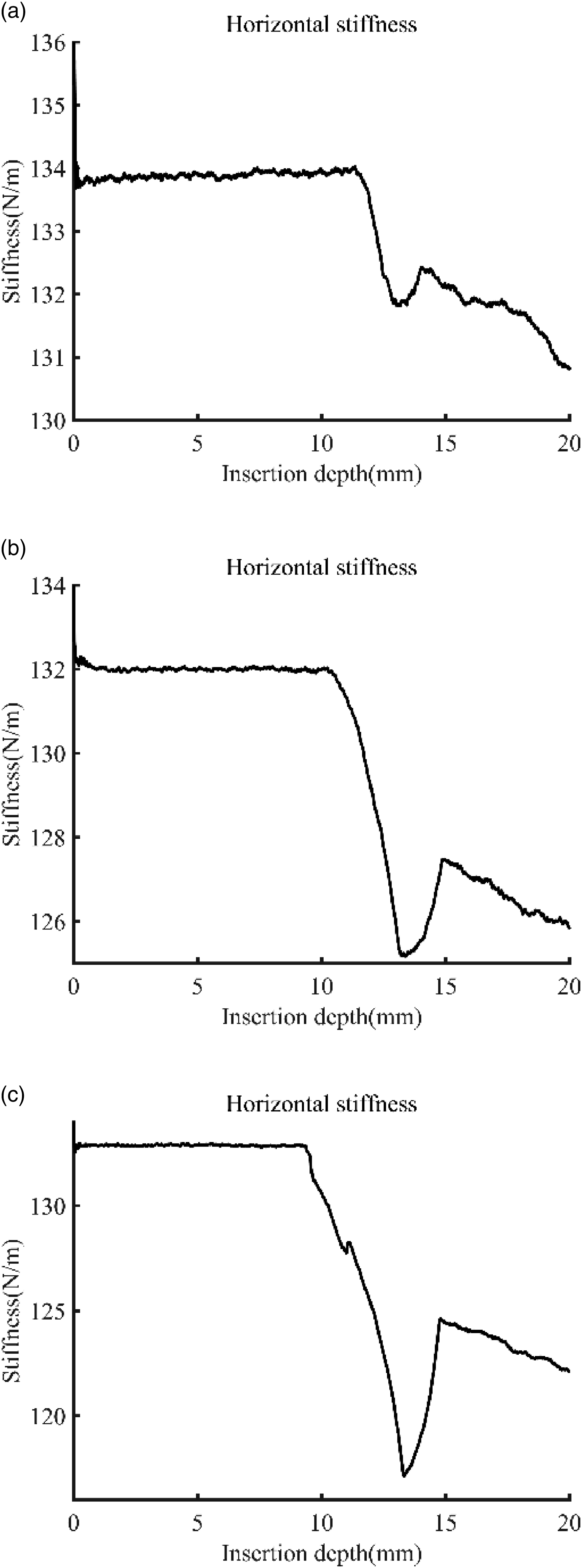
To verify the effectiveness of the compliant robot system, shaft-hole assembly experiments are conducted as shown in Figure 10 under different conditions: (a) horizontal offset position Shaft-hole assembly conditions: (a)–(d) horizontal deviation position error equal to (a)–(c) Control position of the slider under horizontal deviation error equal to (a)–(c) Stiffness control performance under horizontal deviation error equal to 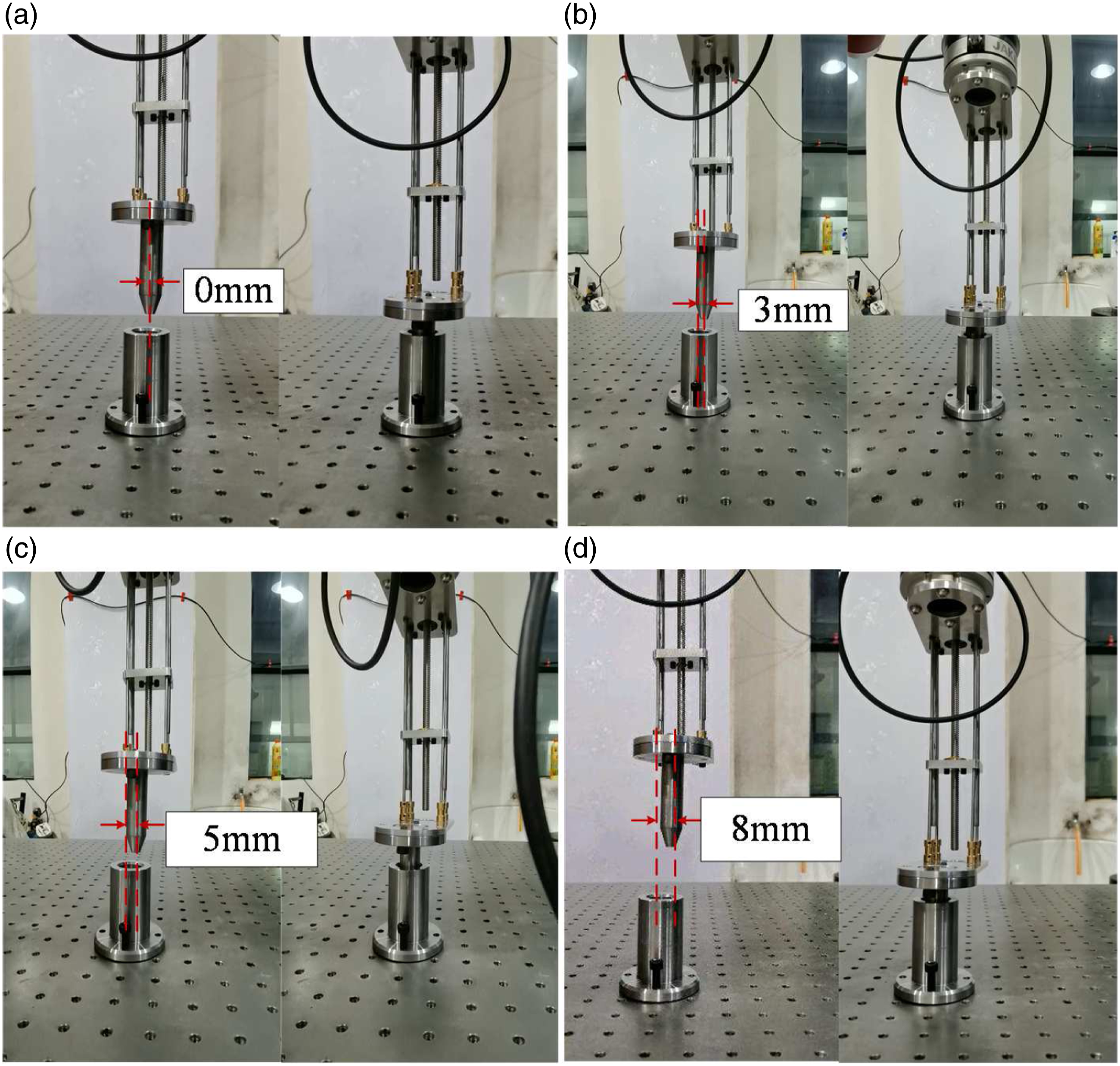
The contact force of the shaft–hole assembly is measured and is shown in Figure 13, the contact force is small due to the compliant wrist even the horizontal deviations reaches to 8 mm. In addition, Figures 13(a)–(c) shows the contact force/torque comparison between the proposed method and the traditional method under different horizontal deviations equal to 3 mm, 5 mm and 8 mm. From these figures, it is observed that when the force and torque at the contact tip increases, the wrist can adjust the stiffness to decrease contact force (within a range of 15 N) and torque (within a range of 5 N-m) quickly without damaging the parts or the robot. In contrast, the contact force/torque of a rigid assembly without a compliant wrist under different horizontal deviations is extremely large (maximum contact force exceeding 200 N and maximum contact torque greater than 50 N-m). Because when the assembly contact force of shaft and hole exceeds the maximum allowable load of robot in all directions, the safety function of manipulator is activated and the joint holding brake is closed. At this time, the contact force will maintain a transient large contact force (more than 400 N or bigger), and the assembly process actually stops and failure. Thus, the assembly control strategy with compliant wrist in this study effectively reduced the contact force and impact between shaft and hole-parts even under large horizontal position error. Contact force/torque comparison between the proposed assembly and the traditional assembly under different horizontal deviations: (a) 3 mm; (b) 5 mm; (c) 8 mm.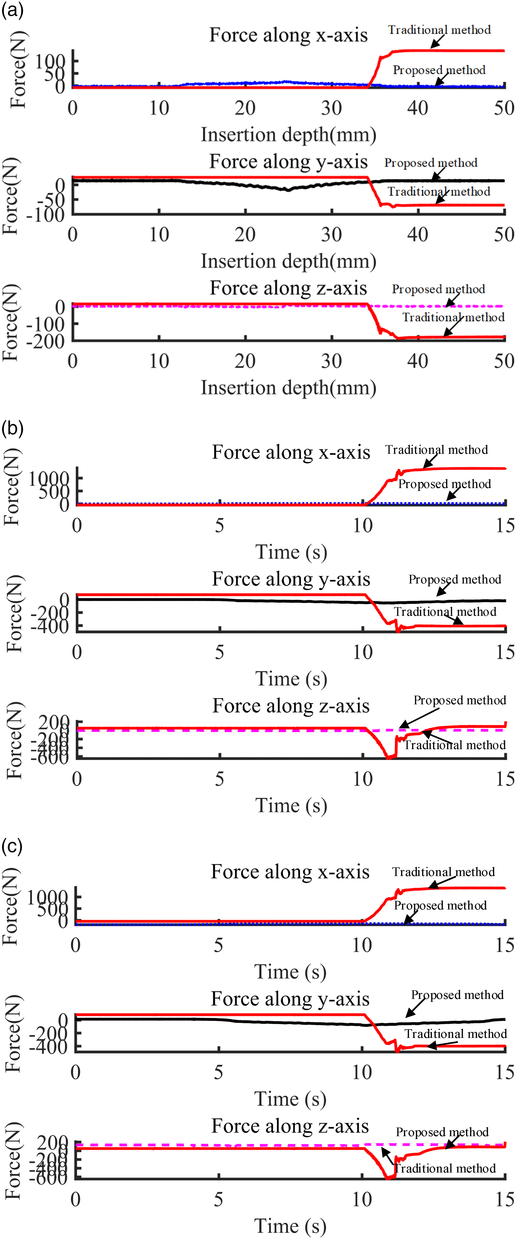
Conclusions
In this paper, a robot with a continuously variable stiffness wrist is used to mitigate the impact of assembly errors and uncertainty according to the automatic assembly requirements. The wrist used a parallel mechanism based on Ni-Ti wire and a slider to achieve variable stiffness operation. As it can produce transverse and rotational deformation, the contact force during assembly is significantly reduced. Unlike the traditional robot assembly, it avoids a large contact force due to position deviations between a shaft and hole as the manipulator is fully rigid. The Cosserat rod theory is used to develop the kinetostatic model to calculate the tip stiffness of the wrist and to evaluate the stiffness of the robot system quantitatively. On this basis, a stiffness control strategy for the wrist is proposed that can be model as a loaded elastic rod and has a no-load kinematics model. The results of experimentation indicated that the proposed fuzzy PD controller possessed better stiffness control properties. Experiments are carried out for stiffness parameter calibration and stiffness control verification. The results of the numerical experiments demonstrated that stiffness variations could be achieved by changing the cantilever length of the Ni-Ti wires. The experiments of stiffness control for shaft-hole assembly verification show that the wrist can adjust the stiffness to decrease the contact force and respond to large deformations, which can effectively complete the shaft-hole assembly.
Footnotes
Declaration of conflicting interests
The author(s) declared no potential conflicts of interest with respect to the research, authorship, and/or publication of this article.
Funding
The author(s) disclosed receipt of the following financial support for the research, authorship, and/or publication of this article: This work was partially supported by the National Key R&D Program of China (2018YFB1308202), the science and technology innovation Program of Hunan Province (2020GK4097), and the Research of deep-sea cobalt - rich crust mining theory and technical parameters project (ZX2021C171).