
Abstract
This study aims to design a nervous system model to drive the realistic muscle-driven legs for the locomotion of a quadruped robot. We evaluate our proposed nervous system model with a hind leg simulated model and robot. We apply a two-level central pattern generator for each leg, which generates locomotion rhythms and reproduces cat-like leg trajectories by driving different sets of the muscles at any timing during one cycle of moving the leg. The central pattern generator receives sensory feedback from leg loading. A cat simulated model and a robot with two hind legs, each with three joints driven by six muscle models, are controlled by our nervous system model. Even though their hind legs are forced backward at a wide range of speeds, they can adapt to the speed variation by autonomously adjusting its stride and cyclic duration without changing any parameters or receiving any descending inputs. In addition to the autonomous speed adaptation, the cat hind leg robot switched from a trot-like gait to a gallop-like gait while speeding up. These features can be observed in existing animal locomotion tests. These results demonstrate that our nervous system is useful as a valid and practical legged locomotion controller.
Keywords
Introduction
Neural circuits called central pattern generators (CPGs) exist in the spinal cord of animals. 1,2 The CPG receives a tonic descending signal from the brain and then generates rhythmic motor activity for locomotion. Biology researchers tested animal locomotion using mesencephalic (decerebrate) cats, 3,4 in which the stimulation of the mesencephalic locomotor region of the midbrain could induce locomotion on a treadmill, demonstrating the existence of the CPG. Another example is a spinal cat; when all the descending pathways from the brain were removed, the cat could not walk, but an injection of dihydroxyphenylalanine administered to the cat stimulated the descending fibers to activate spinal neurons and allowed the cat to walk on a treadmill. 5 Similar experiments have been conducted on dogs and mice. 6 –8 Based on the findings, a spinal network of neurons plays a pivotal role in generating the rhythm and leg trajectory for legged locomotion.
For the mesencephalic cat, the walking speed increased when the stimulation of the descending pathway to CPG was strengthened. 3 Interestingly, it was also reported that while the strength of the descending input was kept constant, only the variation of the speed of the treadmill allowed the hind limbs of the mesencephalic cat to walk by autonomously adapting to the treadmill speed. 4 In the experiment, the cyclic duration of locomotion increased as the treadmill speed decreased. Similarly, spinal cats started walking when the treadmill belt was moved and continued walking according to the treadmill speed. 5 Although the detailed mechanisms of those speed adaptations are not clear, we can assume that an animal is capable of autonomously adapting to the external speed variation without intervention from its brain by depending on the effects of sensory feedback from its legs. The change in the internal states of the CPG in those adaptive locomotions, in which the legs are forcibly moved by external force from the treadmill, should be different from that in the speed adaptation evoked by an increase in the descending signal to the CPG.
We proposed a two-level CPG model to drive a single leg with three joints in our previous simulation work. 9 The CPG consisted of a rhythm generation (RG) part to generate basic locomotion rhythms and a pattern formation (PF) part to synergistically activate a different set of muscles in each of the four sequential phases (swing, touchdown, stance, and liftoff). There were motoneurons (Mn) under the PF part to activate the corresponding muscle according to the driving signal from the PF neurons. A measured leg load was fed back to the leg’s CPG. We applied the realistic CPG-based spinal neuron model to a simulated muscle-driven quadruped model modeled on a cat and demonstrated stable dynamic walking in the simulation. 9 In the article, we changed its speed by adjusting the descending tonic input to the CPG, as observed in mesencephalic cats. 3
In our present study, we built a hind leg simulated model and robot based on the biological experiments of the mesencephalic and spinal cats. We demonstrated whether our previously proposed CPG without intervention from brains (without changing any parameter, not even the descending signal to CPG) could autonomously adapt to external speed variations by autonomously adjusting the rhythm and trajectory of the legs through sensory feedback to the CPG. Based on the results, we evaluated the validity and practicality of our neural model as a bioinspired locomotion controller. Our goal is to develop a locomotion controller for a realistic quadruped robot driven by artificial muscle actuators.
First, we built a hind leg model modeled on a cat in simulation. Each leg has three rotary joints around the pitch axis driven by six muscle models, including two two-joint muscles. The torso with the two hind legs was towed by two active wheels in front, and the cat hind leg model was forced to be pulled at an arbitrary speed. This simulation reproduced the experimental environment of a mesencephalic and spinal cat with their hind legs forcibly pulled backward on a driving treadmill. As we gradually increased the speed of the wheels by 0.85 m/s, the hind leg model was capable of continuing walking by autonomously adjusting its cyclic duration and stride in wide ranges, despite all the fixed parameters, including the descending input to the CPG. We did not observe functional breakdown in the CPG, such as divergence, convergence, or halt of the neural output because it was appropriately adjusted through leg loading feedback.
Next, we implemented our controller on a cat hind leg robot. Each leg of the robot was equipped with six pneumatic artificial muscles that drive three-leg rotary joints around the pitch axis, similar to the simulation. The front body was supported such that the body did not move on the treadmill, similar to the experiments of mesencephalic and spinal cats, and the hind legs were put on the treadmill. While the treadmill was speeding up, the robot walked at a speed of up to 0.8 m/s and then ran at a speed of up to 2.5 m/s, without changing any parameters. Moreover, we observed a gait transition, in which the phase difference between the left and right legs was out of phase while walking and nearly in phase while running, such as galloping.
The simulation and robotic results were similar to the autonomous adaptation to the treadmill speed observed in mesencephalic and spinal cats, suggesting that our proposed nervous system is valid.
Several other studies have also focused on a realistic neuromorphic CPG to reproduce the realistic movement of musculoskeletal legs of an animal model. Hunt et al. 10 developed a hind leg robot modeled on a dog. Each leg joint was controlled by the corresponding single-level CPG and was driven by an antagonistic pair of artificial muscle actuators. The robot did not have two-joint muscles, which helps fast and energy-efficient locomotion. The robot succeeded in reproducing realistic walking on a treadmill. They also used the same method for a rat simulation model’s hind leg walking 11 and extended the single-level CPG model to a two-level CPG. This enabled the rat hind leg model to walk with a more realistic leg trajectory by synergistic joint activation. 12 Maufroy et al. 13 demonstrated the walking of cat hind legs in simulation. Each leg had three joints syneistically driven by seven muscle models. They used a two-level CPG consisting of the neural phase generator proposed by Wadden and Ekeberg 14 and a motor output shaping stage as the RG and PF parts, respectively. However, their model was very complex with a large number of neurons, suggesting that parameter tuning for a real robot would be difficult. They also succeeded in the forelegs walking, using the same method. 15 The most similar two-level CPG to our approach is Markin et al.’s model 16 in which each CPG controlled three joints driven by nine muscle models for each leg, allowing simulated cat hind legs to walk. Their two-level CPG was extended from their previous model proposed by Markin et al., 17 which drove a single-joint limb. However, their model also seems too complex to use for a robot’s locomotion controller because their aim was to develop a testbed to study spinal control of locomotion from a physiological aspect, unlike ours. All of these realistic animal models and robots performed well, but none of the related works and other animal locomotion models and robots with simplified CPG models 18 –33 focused on autonomous adaptation to external speed variation.
We achieved the reproduction of the autonomous speed adaptation observed in the biological tests on our simulated model and robot with the previously proposed neural controller and the implementation of the controller on the robot. Therefore, the controller could be used for prospective bioinspired quadruped robots driven by artificial muscle actuators. In addition, since the mechanism of the speed adaptation is still not clear in biology, our achievement may help reveal the principle of the function in an animal.
Methods
Simulated cat hind leg model
We built a cat model towing its hind legs in the robot simulator called Webots, 34 as shown in Figure 1(a). It weighs 10 kg in total. The torso is a rigid body. The two active wheels replace its forelegs and pull the hind legs, reproducing the experiment where the hind legs of the mesencephalic 4 and spinal 5 cats were pulled backward by the treadmill. We used this particular configuration in the simulation due to difficulties implementing treadmill motion in the simulator. The torso can tilt around the passive pitch joint on the axle shaft of the front wheels, allowing the hip position to rise and fall freely. If the hind legs then do not keep up with the speed of the wheels, the hip lowers and the hind legs are dragged, and the locomotion fails.

(a) Cat hind leg model towed by two active wheels. (b) Muscle placement in each hind leg.
We briefly review the mechanism of each hind leg, which is the same as in our previous cat-simulated model. 9 Each hind leg has the hip, knee, and ankle joints around the pitch axis, and these joints are driven by six representative muscles, including two two-joint muscles. The muscle placement in each hind leg is shown in Figure 1(b). The lengths of the leg segments and the position of the muscle attachments were modeled on a cat as in Reighard and Jennings 35 and Krouchev et al., 36 respectively.
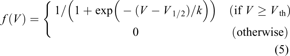
We used a muscle model proposed by Brown et al.. 37 The output force to each muscle is defined as follows

where
Cat hind leg robot
To demonstrate that the autonomous speed adaptation observed in the simulation can be achieved even in a cat hind leg robot and that our proposed controller can be installed in a real robot in practice, we built a cat hind leg robot that locomoted on a treadmill, as shown in Figure 2. It is 480 mm long and 420 mm wide and weighs 3.0 kg. The robot’s configuration is similar to that in the simulated model. The torso can tilt around the passive pitch joint put in the front edge of the torso, allowing the legs to be dragged when the robot cannot keep up with the treadmill speed. This constraint leads to similar effects to the stepping experiments by the hind legs of the mesencephalic 4 and spinal 5 cats, in which their front bodies were suspended and the movement was limited to the sagittal plane.

Cat hind leg robot on a treadmill.
Similar to the simulated model (Figure 1(b)), each leg has three joints and six pneumatic artificial muscles (two two-joint muscles and four single-joint muscles). Each actuator is a McKibben-type pneumatic artificial muscle 38 manufactured by Kanda Tsushin Kogyo Co., Ltd., Tokyo, Japan, which has similar features to that of an actual muscle. All the muscles have a maximum tension of 800 N and a maximum shrinkage factor of 34%. The relaxed muscle length is 140 mm for the hip and ankle flexors, 175 mm for the hip and knee extensors, and 180 mm for each two-joint muscle. An air compressor (TFP37C-10 by ANEST IWATA, 3176 Shinyoshida-cho, Kohoku-ku, Yokohama, Japan) supplies a constant 0.4 MPa of compressed air. The artificial muscle contracts when the compressed air is supplied and relaxes when air is released. In addition, the muscle works as a tension spring while the air is trapped in it. These air circulations are controlled by electromagnetic valves. Each muscle has 3-port and 2-port air ON/OFF solenoid valves (VZ412-5MZ and VX230AA by SMC Corporation, Tokyo, Japan) for inputting compressed air (inputting time) and releasing trapped air (releasing time), respectively. We used 24 valves in total.
Air from the compressor is decompressed and supplied to the muscles by adjusting the inputting to releasing time ratio. The ratio represents the motoneuron’s activity
Although it is difficult to control air pressure as precisely as an animal controls its muscular force, we demonstrate that our robot can support its body and reproduce its leg trajectory for locomotion.
Each joint has an optical rotary encoder (HEDS-5500#A11 by Avago Technologies Japan, Ltd., Tokyo, Japan) to detect its angle. We estimate the force (leg load) applied to the knee and ankle’s two-joint muscle when it is extended in the stance phase (see the “Leg loading feedback” section for details). As this force is also exerted in the swing phase, we use two additional force sensors (FlexiForce A201-100 by NITTA Corporation, 4-4-26 Sakuragawa, Naniwa-ku, Osaka, Japan) on the bottom of each foot to determine if it is touching the ground. An inclinometer and a rate gyro are mounted on the torso to detect its body tilt for evaluation. We use a robot control board (HRP-3P-CN & MCN by General Robotics Inc., 1-1-1 Umezono, Tsukuba-shi, Ibaraki, Japan). The robot is controlled through an online system with a sampling time of 2 ms. The robot is tethered to an air compressor for the muscle actuators and a power supply, which are external to the robot.
Neural system
We used our previously proposed two-level CPG model 9 for our present cat hind leg simulated model and robot with the exception of the Inab neuron to implement a stretch reflex. Since the stretch reflex had mainly worked to ensure walking stability in the lateral plane in our previous study, 9 it was not needed for planar locomotion in this article. The equations of each neuron model used in the two-level CPG model (equations (2) –(5)) are briefly reviewed in the “Basic design of two-level CPG model” section. We describe the leg loading feedback in the “Leg loading feedback” section. The previously applied equation (equation (6)) was used for our present simulation. The parameter values in equations (2)–(6) were heuristically determined again to ensure our simulated model and robot could adapt to a wide range of speeds in a stable manner. New equations (7) and (8) were used for our robot as leg loading feedback. We detail these in the “Leg loading feedback” section.
Basic design of two-level CPG model
Figure 3 shows the detailed diagram of our two-level CPG for each leg. The CPG is divided into two layers: the RG part that produces basic locomotion rhythms and the PF part that synergistically activates a different set of muscles in each of the four sequential phases (swing, touchdown, stance, and liftoff). The signals from the CPG are sent to motoneurons (Mn) to drive the corresponding muscles. The RG part consists of a flexor neuron (RG-F) and an extensor neuron (RG-E). They mutually inhibit each other through an interneuron (In) and alternate activation, creating a rhythmic motion. The PF part has four PF neurons, namely

Detailed diagram of the proposed two-level CPG for each leg. CPG: central pattern generator.
The membrane potential of the main neurons in the RG and PF parts and the six motoneurons (i.e. RG-F, RG-E, PF{sw, td, st, lo}, and Mn{1, 2,…, 6} in Figure 3) is expressed as follows

and the membrane potential of the interneurons (In in Figure 3) is expressed as follows

where C is a neuronal capacitance, V is the average membrane voltage of the neuron,
The currents are expressed as follows

where
where

Hard-wired CPG network between the two legs. Each dashed line oval shows a CPG. The small black circles indicate inhibitory synaptic connections. CPG: central pattern generator.
Leg loading feedback
Sensory feedback is vital for the hind legs to autonomously adapt to external speed variation without changing the descending input to the CPG or the CPG parameters. Biological findings have reported sensory feedback to the CPG (e.g. the lengths of the extensor and flexor around a hip joint and that of an ankle joint flexor, 39 load from the Golgi tendon organ in an ankle joint extensor, 40 and load from load-sensitive cutaneous afferents in the paw pad 41 ).
We focused on leg loading feedback, which is reported to be most important to support the body and to reset the rhythm. 40,42 We decided to input a leg load to the RG flexor neuron to make it inhibited, as shown in Figure 3, based on Pearson’s findings, 40,43 in a realistic way. The feedback inhibits the activation of the RG flexor neuron during the stance phase, resulting in the extension of the stance duration. Further, an unloaded leg can be quickly led to the swing phase.
In our simulated model, the leg loading feedback was defined as follows

where
We estimate the force applied to the knee and ankle’s two-joint muscle actuator, which covers an ankle joint extensor, when it is extended in the stance phase. This is input into the CPG as leg loading feedback because the force applied to the ankle joint extensor is often regarded as the leg load in locomotion experiments on decerebrate cats. 40 Before the foot touches the ground during locomotion, the two-joint muscle actuator contracts to the shortest length of 119 mm by fully trapping the compressed air (0.4 MPa). We estimate the contraction force, regarded as the leg load, from its extension in the following stance phase. Figure 5 compares the force against the muscle’s extension from 119 mm, measured in static conditions. The muscle actuator shows similar characteristics to that of a linear spring. As a result, we calculate force (leg load) by the following equation

where

where

Force against extension of the knee and ankle’s two-joint muscle actuator from the shortest length of 119 mm, measured in static conditions.
Results
We tested if the cat hind leg model and robot could autonomously adapt to a wide range of speed, similar to mesencephalic and spinal cats. We kept all the neural and muscle parameters, including the tonic descending input to the CPG, fixed in the simulations and robot experiments. We prepared a simulated model and robot with and without leg loading feedback for comparison.
In the simulation, the front active wheels (Figure 1) towed and gradually accelerated the body. Consequently, the cat hind leg model without leg loading feedback failed in walking at a speed of 0.45 m/s, but the model with leg loading feedback successfully achieved walking at speeds of up to 0.85 m/s (see Supplementary Movie 1). In the robot experiments, we gradually accelerated the treadmill. As a result, the robot without leg loading feedback failed walking at a speed of 0.46 m/s, whereas the robot with it walked at a speed ranging 0–0.8 m/s and ran at a speed ranging 0.8–2.5 m/s (see Supplementary Movie 2).
In the following sections, we evaluate these results by observing the walking cyclic duration (see the “Evaluation of autonomous adaptation to speed variation based on cyclic duration” section) and stride (see the “Evaluation of autonomous adaptation to speed variation based on stride” section), which are generally used to evaluate locomotion and compared these with results for real cats.
Evaluation of autonomous adaptation to speed variation based on cyclic duration
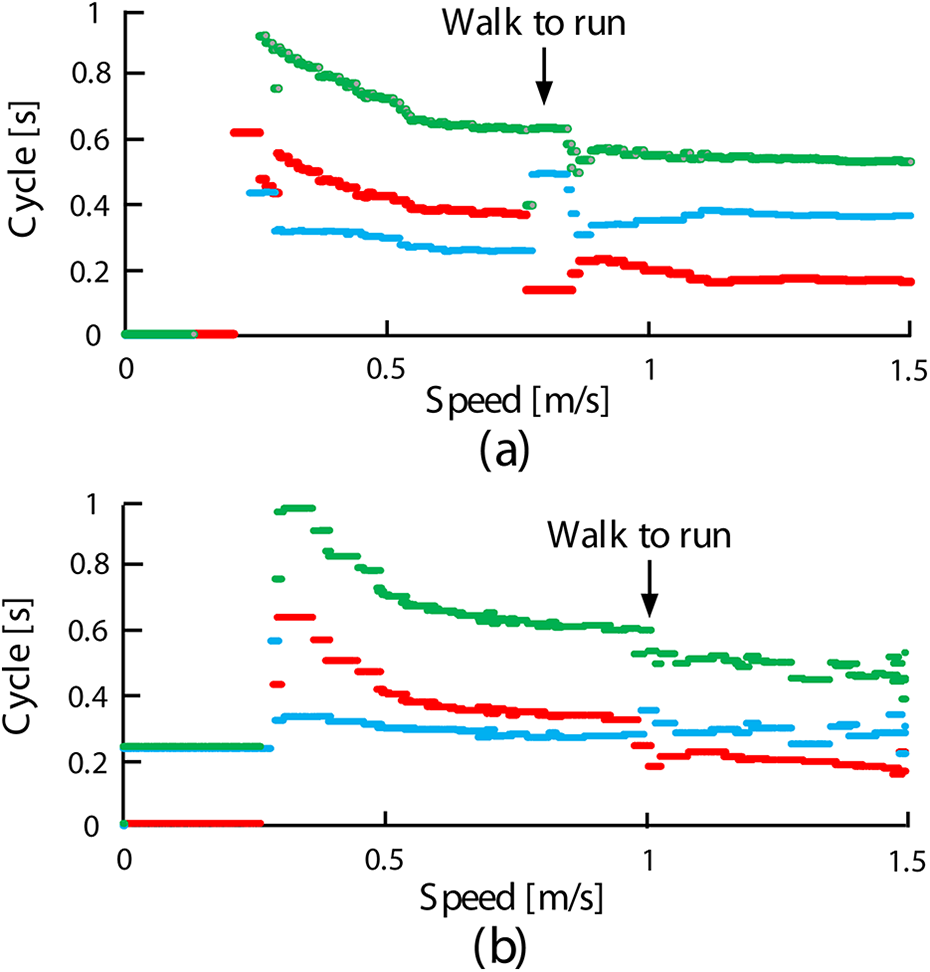
Figure 6(a) to (c) shows the results of the simulation, the robot experiment, and a cat experiment, 44 respectively. In each graph, stance duration (red dot), swing duration (light blue dot), and cyclic duration (the sum of the stance and swing durations: green dot) at each locomotion speed in the horizontal axis are plotted.

Swing, stance, and cyclic durations with speed during autonomous speed adaptation. Swing (light blue dots), stance (red dots), and cyclic (green dots) durations at each speed in (a) the cat hind leg simulated model, (b) the cat hind leg robot, and (c) a real cat. 44 The transparent yellow and red areas show the same ranges.
To compare the results of our trials with those of the cat experiment, the transparent yellow area in Figure 6(a) and the transparent red areas in Figure 6(b) are highlighted in Figure 6(c). In these areas, our results were similar to those of the cat experiment. Specifically, in every graph of Figure 6, as the speed increased, the stance and cyclic durations (red and green dots) decreased, whereas the swing duration (light blue dot) did not significantly change. The plots were discrete at the beginning of the transparent areas in Figure 6(a) and (b) because it was difficult to achieve regular walking at very slow speeds. Figure 6(b) illustrated that the robot’s locomotion was temporarily disturbed between approximately 0.75 m/s and 0.9 m/s (just after the transparent red area). Since the locomotion was autonomously switched from walking to running during the disturbance (this can be confirmed by the fact the swing durations became longer than the stance durations after the disturbed moment), the robot succeeded in adapting to higher speeds than the simulated model. As a result, the cat hind simulated model and robot were capable of autonomously adapting to speeds ranging 0.14–0.85 m/s and 0.27–2.5 m/s, respectively. In contrast, the swing, stance, and cyclic durations rarely changed in the simulated model or robot without leg loading feedback and both were only able to adapt to speeds of up to approximately 0.45 m/s.
Evaluation of autonomous adaptation to speed variation based on stride
Figure 7 shows the stride and foot position at each speed in (a) the cat hind leg simulated model, (b) the cat hind leg robot, and (c) a real cat. 44 In each graph, the red, orange, and green dots show stride, horizontal toe position with respect to the hip at touchdown, and that at liftoff, respectively. The transparent blue areas show the same ranges for comparison.
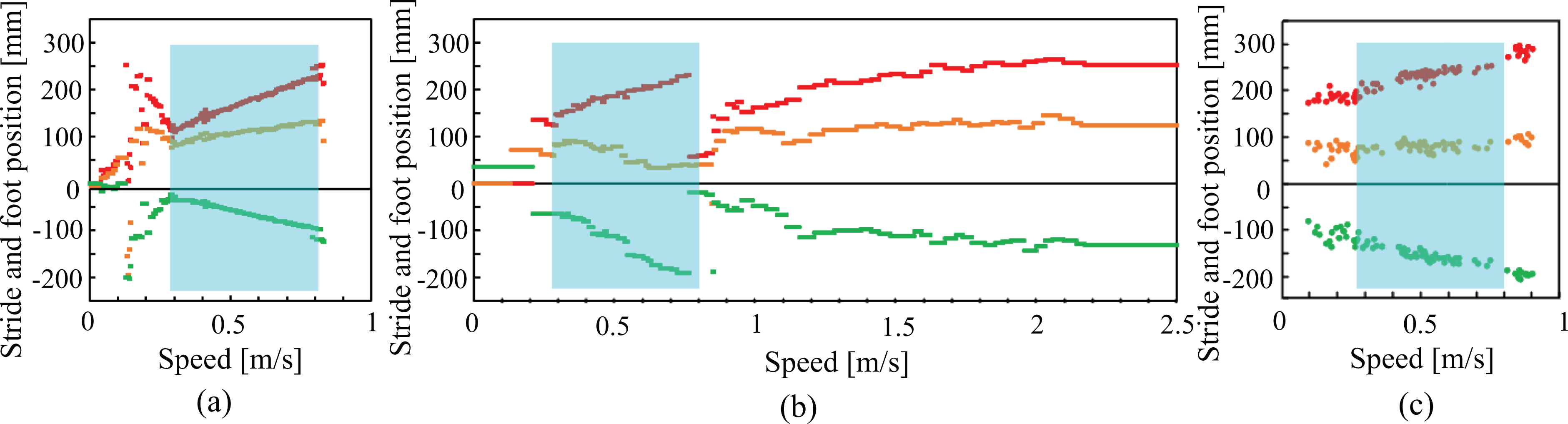
Stride and foot position at each speed in (a) the cat hind leg simulated model, (b) the cat hind leg robot, and (c) a real cat. 44 In each graph, the red, orange, and green dots show stride, horizontal toe position with respect to the hip at touchdown and that at liftoff, respectively. The transparent blue areas show the same ranges.
Similar to Figure 6(a) and (b), the locomotion was irregular at very low speeds (before the transparent blue areas), but during the transparent blue area, the simulated model (Figure 7(a)) and robot (Figure 7 (b)) demonstrated similar aspects to the real cat (Figure 7(c)). Specifically, the strides (red dots) were extended as the speed was increased. In particular, the toe positions at liftoff (green dots) were pulled more backward than the toe positions at touchdown (orange dots).
The robot was able to adapt to higher speeds than the simulated model because the stride and foot positions in Figure 7 were reset at the end of the transparent blue area when the locomotion switched from walking to running.
Theory of autonomous speed adaptation
The autonomous speed adaptation, explained in the “Evaluation of autonomous adaptation to speed variation based on cyclic duration” section and the “Evaluation of autonomous adaptation to speed variation based on stride” section, is a result of the CPG autonomously adjusting RG-F neuron activation through leg loading feedback (“Leg loading feedback” section).
Figure 8 shows the RG-F output, hip joint angle, and left hind leg load when the robot was running at 1 m/s. In the first half of the stance phase, a large load is presented on each leg, as shown in α of Figure 8. This delays the swing phase by inhibiting the RG-F neurons to maintain the stance period, providing leg support for the body. Decreased leg load is presented in the stance phase’s last half (β in Figure 8) because of the leg being pulled backwards (ρ in Figure 8), leading to reduce RG-F inhibition. This results in an earlier shift to the swing phase, preventing the leg from dragging.

Experimental results of our cat hind leg robot with leg loading feedback running at 1 m/s.
Even at high speeds, leg loading feedback prevented the robot from folding its posture by supporting the body in the stance phase’s first half and prevented the legs from dragging while striding (Figure 7(a) and (b)) by quickly shifting to the swing phase in the last half.
As leg loading feedback is inactive in the swing phase, it did not affect the swing duration of each speed, as shown in Figure 6(a) and (b).
As

Comparison of two CPG sensory feedbacks for the left hind leg joint angles when the robot is running at 1.0 m/s with (a) only leg loading feedback and (b) both leg loading and hip trigger feedback. CPG: central pattern generator.
Comparisons to hip trigger feedback for CPG
In sensory feedbacks for CPGs, as described in the “Leg loading feedback” section, the flexor length around a hip joint 39 is likely to affect autonomous speed adaptation. When the flexor extends to a certain length, the leg is reset from the stance phase to swing to prevent dragging. We called this hip trigger feedback. We applied this feedback to our robot and compared its effectiveness to leg loading feedback.
Definition of hip trigger feedback
Hip trigger feedback is defined as follows

where
Autonomous speed adaptation with only hip trigger feedback
We replaced the leg loading feedback (equation (8)) in the robot with hip trigger feedback (equation (9)) and conducted the same experiments as in the “Evaluation of autonomous adaptation to speed variation based on cyclic duration” section and the “Evaluation of autonomous adaptation to speed variation based on stride” section. We found that the robot was only capable of adapting to approximately 0.25 m/s –1.0 m/s. This demonstrates that the adaptable speed range is limited with this feedback. Additionally, the locomotion lacked smoothness and consistency using this method, for example, the feet often left the ground during the stance phase and there was variation between experimental data.
Autonomous speed adaptation with hip trigger and leg loading feedback
We applied both hip joint and leg loading feedback to our robot. Figure 9 shows the angles of the three left hind leg joints, when the robot ran at 1.0 m/s with (a) only leg loading feedback and (b) both feedbacks. As shown in the figure, adding hip trigger feedback was effective in preventing the leg from being pulled excessively back (A in Figure 9(b)). However, since the stride was also restricted, the robot could only adapt up to 1.5 m/s.
Swing, stance, and cyclic durations of the robot with only leg loading feedback and with both feedbacks are shown in Figure 10(a) and (b), respectively (Figure 10(a) is the same as Figure 6(b)). Locomotion was disturbed during the walking to running transition in both cases but was stable afterwards in Figure 10(a) whereas data fluctuated in Figure 10(b), indicating instability. This was because the hip joint angle was always limited at the stance to swing transition by hip trigger feedback.
Swing, stance, and cyclic durations during autonomous speed adaptation by the robot with (a) only leg loading feedback and (b) both leg loading and hip trigger feedback.
When we used greater values for the threshold angle
Based on the comparative results, we suggest that leg loading feedback can be used to smooth locomotion and enhance autonomous speed adaptation rather than hip trigger feedback.
Autonomous gait transition from trot-like gait to gallop-like gait while the robot runs
We observed autonomous gait transition during the autonomous speed adaptation in the robot experiments with leg loading feedback (see Supplementary Movie 3). Figure 11 (I) shows the treadmill velocity (green line) and the body tilt around the pitch axis (red line), which is positive when the robot is tilted forward. In Figure 11 (I), (a) indicates the period in walking, and (b) and (c) that in running. A trot-like gait, in which the phase differences between the two hind legs were out of phase, is found in (a) and (b), and a gallop-like gait, in which they were nearly in phase, is shown in (c). Figure 11 (II) and (III) shows states in (a) of Figure 11 (I) and in the transition from (b) to (c), respectively. In each graph, the activation rate of the RG-F neuron and leg load of each leg (light blue: left leg and purple: right leg) are shown in the upper half and in the bottom, respectively. The red wavy line denotes the body pitch angle, as in Figure 11 (I). Figure 11 (III) shows that just after the body started oscillating significantly at around 43 s between (b) and (c), the phase differences between the two legs abruptly changed to nearly in phase. We did not explicitly program the phase differences between the two legs but the gait autonomously transitioned like an animal according to the variation of the body tilt.

Gait transition in the cat hind leg robot. (I) shows the treadmill velocity (green line) and the body tilt around the pitch axis (red line), which is positive when the robot is tilted forward. (II) and (III) show the states in (I). In (II) and (III), the activation rate of the RG-F neuron and leg load of each leg (light blue: left leg and purple: right leg) are shown in the upper half and in the bottom, respectively. RG-F: RG part consists of a flexor neuron.
Conclusions
We applied our CPG-based neural controller to our hind leg simulated model and robot modeled on a cat and forced them to change their speed by the active wheels and the treadmill. We found that the cat model and robot could adapt to a wide range of speed by autonomously adjusting the cycle and stride, similar to locomotion tests by mesencephalic and spinal cats, despite all the parameters (including the tonic descending input) being fixed. In their trials, they shortened their stance periods more than their swing periods as their speed increased. In addition, their backward stride was larger than their forward stride. Similar resulting features can be seen in autonomous speed adaptation of mesencephalic and spinal cats.
In addition, the gait of our cat hind leg robot autonomously switched from a trot-like gait to a gallop-like gait, similar to an animal.
Our simulated hind leg model and robot achieved similar results to those in an animal, and we did not see any collapse of the CPG, such as the divergence, convergence, or halt of the CPG outputs. Although our CPG model is simpler than the comparable Markin et al.’s CPG model 16 (as described in the “Introduction” section), we consider ours practical enough for use as a biomimetic locomotion controller for a robot, due to its autonomous speed adaptation ability as demonstrated in this article, as well as stable quadrupedal walking shown in a previous simulation. 9
Footnotes
Acknowledgments
We would like to thank Kosuke Inoue and Keisuke Yagi for their valuable comments and advice.
Declaration of conflicting interests
The author(s) declared no potential conflicts of interest with respect to the research, authorship, and/or publication of this article.
Funding
The author(s) disclosed receipt of the following financial support for the research, authorship, and/or publication of this article: This work is supported by the Japan Society for the Promotion of Science (Grant-in-Aid for Scientific Research (C), Grant Number: 18K11489).
Supplemental material
Supplemental material for this article is available online.
References
Supplementary Material
Please find the following supplemental material available below.
For Open Access articles published under a Creative Commons License, all supplemental material carries the same license as the article it is associated with.
For non-Open Access articles published, all supplemental material carries a non-exclusive license, and permission requests for re-use of supplemental material or any part of supplemental material shall be sent directly to the copyright owner as specified in the copyright notice associated with the article.