
Abstract
Multidimensional force loading has been widely used in the fields of component and material testing. The pneumatic-driven multidimensional force loading parallel mechanism can meet the requirements of complex force loading. A three-dimensional loading robot based on a pneumatic three-universal–prismatic–universal parallel mechanism is designed to apply time-varying three-dimensional loads on a target. Based on the principle of vector superposition, inverse and forward kinematics are deduced. A second-order mathematical model of a metal seal pneumatic cylinder driven by a flow proportional valve is established. Based on the immersion and invariance technique, the leakage flow in the cylinder is taken as the interference term and estimated. Meanwhile, because of the strong nonlinearity of the actuator, based on suitable disturbance estimation, the control rate of the system is designed through the sliding mode surface, and the stability of the control algorithm is analyzed on the basis of the Lyapunov stability theory. The experimental results show that the immersion and invariance controller exhibits a better control performance than the proportional–integral–differential controller: the steady-state control mean square error is reduced by approximately 21% on average and the dynamic (0.2 Hz) tracking mean square error is approximately 10.35 N.
Introduction
Multidimensional force loading has been widely used in the fields of component and material testing, 1,2 medical rehabilitation, 3,4 and so on. It is of great significance to carry out multidimensional force loading accurately. The multidimensional force loading parallel mechanism has the advantages of large stiffness, error equalization, and sufficient multidimensional output force. 5,6 Therefore, it is an important technique to realize complex force loading. Zhao et al. 7 designed a six-dimensional force loading device based on a six-universal–prismatic–universal (UPU) parallel mechanism. The device was used to apply multidimensional force loads. Wang and Huang 8 designed a multiaxis loading test stand based on an orthogonal parallel mechanism. Using this system, they applied precise multidimensional loads to the assembly structure and obtained accurate data for reliability and fatigue tests.
A three-UPU robot is a parallel mechanism with limited degrees of freedom,
9
where U and P represent the universal and prismatic pairs, respectively. The robot comprises three retractable connecting rods, a static platform, and a dynamic platform. Ji and Wu
10
established a kinematic model of a three-UPU parallel mechanism and obtained a closed-form solution of this model. Chen et al.
11
proposed a new method to analyze the kinematics of a three-UPU parallel mechanism. Han et al.
12
analyzed the kinematic sensitivity of three-UPU parallel mechanism and verified it experimentally. Dehkordi et al.
13
developed a new type of horizontal three-UPU parallel mechanism driven by three linear motors. Based on this mechanism, a gravity compensation algorithm was studied. Ashith Shyam and Ghosal
14
proposed a solar tracking system based on a three-UPU parallel mechanism and carried out trajectory planning and control experiments on the system. The accuracy of the position-pose control of the mechanism was 180 µm. Bhutani and Dwarakanath
15
designed a three-UPU-type mechanism driven by a high-precision linear motor and verified its performance. The accuracy of the position-pose control of the mechanism was 100 µm. Li et al.
16
proposed a mixed
Parallel robots are mainly driven by hydraulic, electric, or pneumatic servo systems. Using metal gap-sealed cylinders as loading drivers not only brings advantages, such as air-driven cleaning, pollution-free operation, simple structure, low cost, and easy maintenance 17 but can also help effectively avoid the high friction forces produced in pneumatic systems. Therefore, for the working conditions of three-UPU robots, it is more advantageous to use metal gap-sealed cylinders as the drivers.
In pneumatic three-UPU robots, the loading control is performed via pneumatic servo control. Recently, numerous studies have been conducted on pneumatic servo control. To overcome the nonlinearity of pneumatic systems, Meng et al. 18,19 designed a pneumatic servo controller based on self-adaptive robustness, where online parameter estimation was applied to obtain the uncertain model parameters. In this system, the effects of the unmodeled parts and the interference were suppressed by nonlinear robustness control. Thus, while ensuring the accuracy of the output force control, the system provides a good degree of transient performance. For tracking a 0.5 Hz sinusoidal trajectory, the maximum tracking error is 4.1 N and the average tracking error is 2.2 N. Meanwhile, the output stiffness can be maintained near its maximum/minimum. Li et al. 20 proposed a sliding-mode controller based on a nonlinear model of a pneumatic servo system. In a force tracking test conducted at a frequency of 1 Hz and an amplitude of 80 N, the average tracking error of the force was less than 5 N. To overcome the chattering while switching the sliding mode surface, the saturation function was adopted to replace the symbol function when constructing the sliding mode surface based on the Lyapunov theory. The ideal control effect was achieved. As the friction force in a pneumatic servo system is relatively high and difficult to measure directly, Sheng and Zhao 21 designed an observer to estimate the friction force in a pneumatic force servo system online based on the extended Kalman filter. They compensated for the friction force in real time. In a step response experiment with an expected output of 1000 N, the adjustment time was less than 1 s, and the average steady-state error was less than 50 N, thus realizing accurate control of the output force.
The main contribution of this article is the proposal of a three-dimensional (3D) force loading system driven by a metal clearance-sealed cylinder based on a 3-UPU mechanism. Because the leakage flow in the cylinder cannot be detected by a flow sensor when the piston is in motion, it is taken as the interference term and estimated on the basis of the immersion and invariance (I&I) theory; then, the accurate mathematical model of the control system is obtained. Owing to the nonlinearity of the pneumatic system, a 3D loading control system based on the sliding mode with fast response and high precision is designed. The conditions for the stability of the controller and the corresponding proof are presented. Finally, we implement 3D loading control of the robot and verify the effectiveness of the method.
The remainder of this article is organized as follows. The structure of the three-UPU robot is introduced in the second section. The kinematic and static analyses are carried out in the third section. The mathematical model of the metal gap-sealed cylinder is established in the fourth section. The controller is described in the fifth section. The experimental results are presented in the sixth section. Finally, the conclusions are stated in the seventh section.
Structure of a 3-UPU robot
A pneumatic three-UPU loading robot system comprises a control system and a robot. Figure 1 shows the mechanism. The control system includes an industrial control computer, data acquisition cards, and proportional flow valves. As shown in Figure 2, the robot consists of metal gap-sealed cylinders, a static platform, universal pairs, a dynamic platform, and a 3D force sensor. The static and dynamic platforms are designed as regular triangular elements. The inner sides of the two universal pairs are connected to the ends of three cylinders, forming three-branch chains. The outer sides of the universal pairs are, respectively, connected to the triangular endpoints of the dynamic and static platforms. The 3D force sensor is connected at the end of the robot and fixed on the support stand.

Working principle of a pneumatic three-UPU loading robot system. UPU: universal–prismatic–universal.

Image of a three-UPU robot. UPU: universal–prismatic–universal.
The 3D force sensor used is a BAYKON BF7512 series multidimensional force sensor with a detection limit of 200 N; the three-axis mutual interference error is approximately 2 N. The MPYE-5-1/4-010B-type proportional flow valve (FESTO, Germany) is used to control the gas flow, and the Advantech PCL1716 data acquisition card is adopted for data acquisition.
Kinematic and static analyses
Kinematic analysis
Figure 3 shows the motion coordinates of the pneumatic three-UPU force loading robot. The static platform forms a regular triangle represented by A
1
A
2
A
3; R is the radius, and O
0 is the center of the circumscribed circle. Pi
(i = 1, 2, and 3) represents the three branches in sequence, and their upper endpoints are represented by Ai
(i = 1, 2, and 3). O
0
x
0
y
0 is set as the absolute coordinate system. The direction from O
0 to branch 2 is the positive direction of x
0. The positive direction of the z
0 axis is perpendicular to the plane A
1
A
2
A in the downward direction. The coordinates of Ai
(i = 1, 2, and 3) are

Coordinates of the three-UPU robot. UPU: universal–prismatic–universal.
The dynamic platform forms a regular triangle represented by M
1
M
2
M
3; r is the radius, and O is the center of the circumscribed circle. Mi
(i = 1, 2, and 3) represents the lower endpoints of the three branch chains. In the moving coordinate system Oxyz, the direction from O to M
2 is the positive direction of the x-axis, and the downward positive direction of the z-axis is perpendicular to the plane M
1
M
2
M
3. The coordinates of Mi
(i = 1, 2, and 3) in the absolute coordinate system are
The vector equation for the three branch chains is shown in the following equation


where the length of the branch i is represented by li
(i = 1, 2, and 3). Assuming that (x, y, z) is the absolute coordinate of point O, then
Taking Δ = R−r, we can obtain the kinematic inverse solution of the robot

where li (i = 1, 2, and 3) is in the range of 420–720 mm, and Δ = 403.5 mm.
Static analysis
The normal vector n
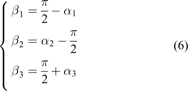
0 of the dynamic platform is set as [0 0 1]T, and the angle

The angle

where l 0 = 570 mm is the initial length of the branch chain.
Taking
According to Eqs. (4)–(6), the 3D load acting at the robot end can be obtained using the following equation

where fi (i = 1, 2, and 3) represents the output forces of the three cylinders.
Equation (7) is solved to obtain the relationship between the output force of the cylinder and the 3D load at the robot end, as expressed in the following equation

where

System modeling
To derive the dynamic mathematical model of a metal gap-sealed cylinder driven by the proportional flow valve (Figure 4), the following assumptions are made based on the characteristics of the compressed air. 22 The temperature change in the gas flow process and the influence of all the connected pipelines on the pressure transmission are ignored. In addition, the flow of gas through the valve port is considered an isentropic process.

Metal gap-sealed pneumatic cylinder driven by a flow proportional valve.
Model of the proportional flow valve
The proportional flow valve is simplified to a first-order system. To compensate for the middle dead zone, 23 we take


where A v is the effective area of the intake or exhaust valve ports, k 1 and k 2 are positive constants that can be obtained using the least-squares method with the flow curve data in the manual operation of the proportional flow valve, U is the actual output voltage signal, and u is the control quantity. Uu and Ul are the upper and lower limits of the dead zone voltage, respectively, set to 4.82 and 5.21V.
The equation of motion when the gas flows through the valve port is

where
In-cylinder pressure model
Assuming that the initial state of the cylinder is fully retracted, the volumes of the inflation and exhaust chambers can be expressed as follows


where yc is the displacement of the piston, Ac is the effective cross-sectional area of the cylinder, Lc is the total displacement of the piston, and Vc is the total effective volume of the cylinder.
The structure of the metal gap-sealed cylinder is different from that of a conventional cylinder, in that there is no seal ring inside the cylinder. The internal leakage flow rate of the adopted gas seal cannot be ignored. According to the assumptions, the pressure differential equation for the pressure difference inside the cylinder is
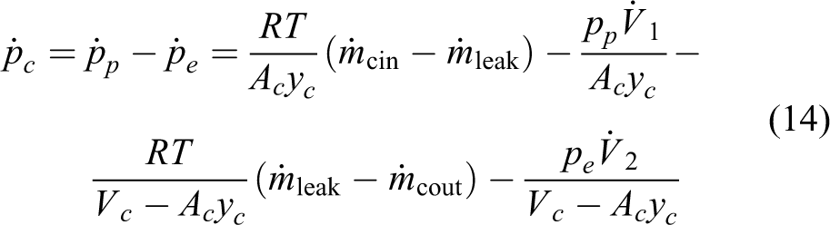
where
Control system model
The second-order approximate model of a single-cylinder loading control system is expressed in the following equation

Loading control
State equation
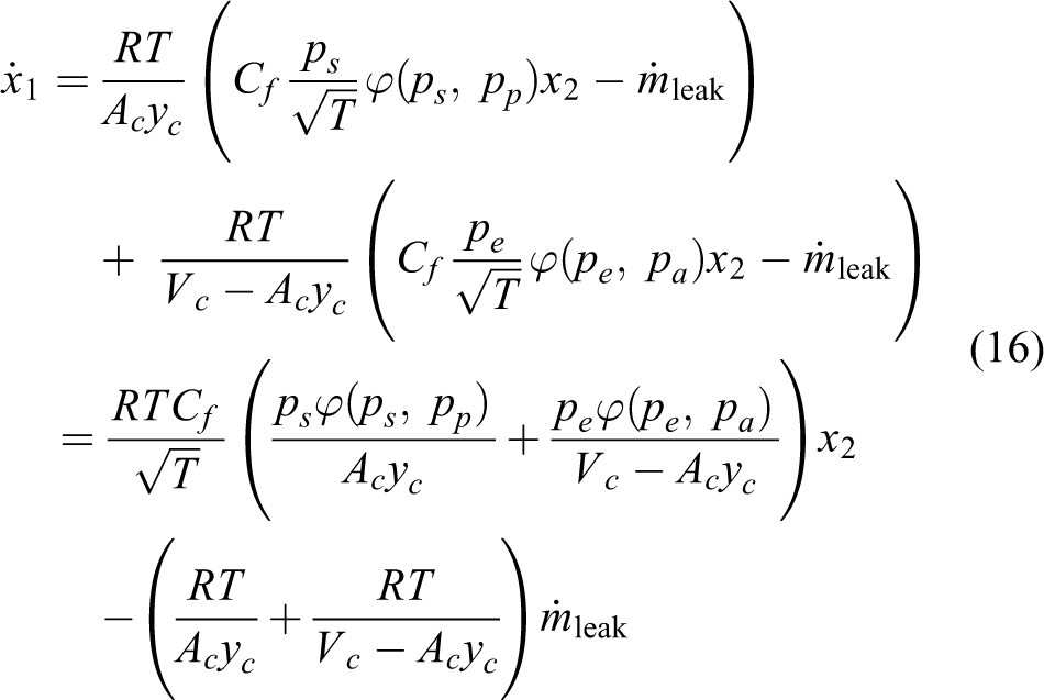
From Eq. (9)

The simultaneous equations, namely Eqs. (16) and (17), are the differential forms of the model

where
Design of self-adaption rate
The basic principle of the I&I theory is to immerse the system state into a specified target manifold. The target manifold can be made attractive by designing a control algorithm, thus ensuring that the system has a global uniformly asymptotical stability at the equilibrium point. 24
The error manifold is defined based on the I&I theory

where
With the assumption that the above error manifold remains unchanged, the loading control system model can be expanded. Comparing with Eq. (18), we have

Here
The load tracking error is taken as follows

where
Differentiating Eq. (21) and solving it with Eq. (18) simultaneously, we obtain the following
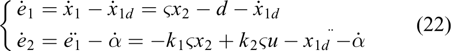
where
Differentiating the manifold error equation yields

The self-adaptive trend is defined as follows

By substituting Eq. (24) into Eq. (23), we get

Let
Differentiating the Lyapunov function

This indicates that the manifold error η is asymptotically stable.
Control rate design
The sliding mode variable structure control is a special type of nonlinear control. This method can be used to effectively design the sliding mode surface. When the system reaches the sliding mode surface, its operation state depends only on the sliding mode surface, regardless of the original parameters of the system, thus overcoming parameter uncertainty. 16
For convenience, Eq. (22) is further simplified

where
We need to ensure that the error e 1 gradually converges to zero while maintaining certain stability in the event of considerable jittering on the sliding mode surface. Considering its characteristics, the hyperbolic tangent function is introduced into the design of the sliding mode surface

where
Eq. (27) is substituted into Eq. (28), and the derivative is

The control mechanism is set to

where
The parameters of the system model expressed in Eq. (18) are unknown, and the self-adaptive rate can be obtained using Eq. (24). Thus, we can estimate the internal leakage flow. The design of the sliding mode surface combined with the hyperbolic tangent function constitutes an I&I controller suitable for three-UPU robot loading control. Figure 5 shows the control logic.
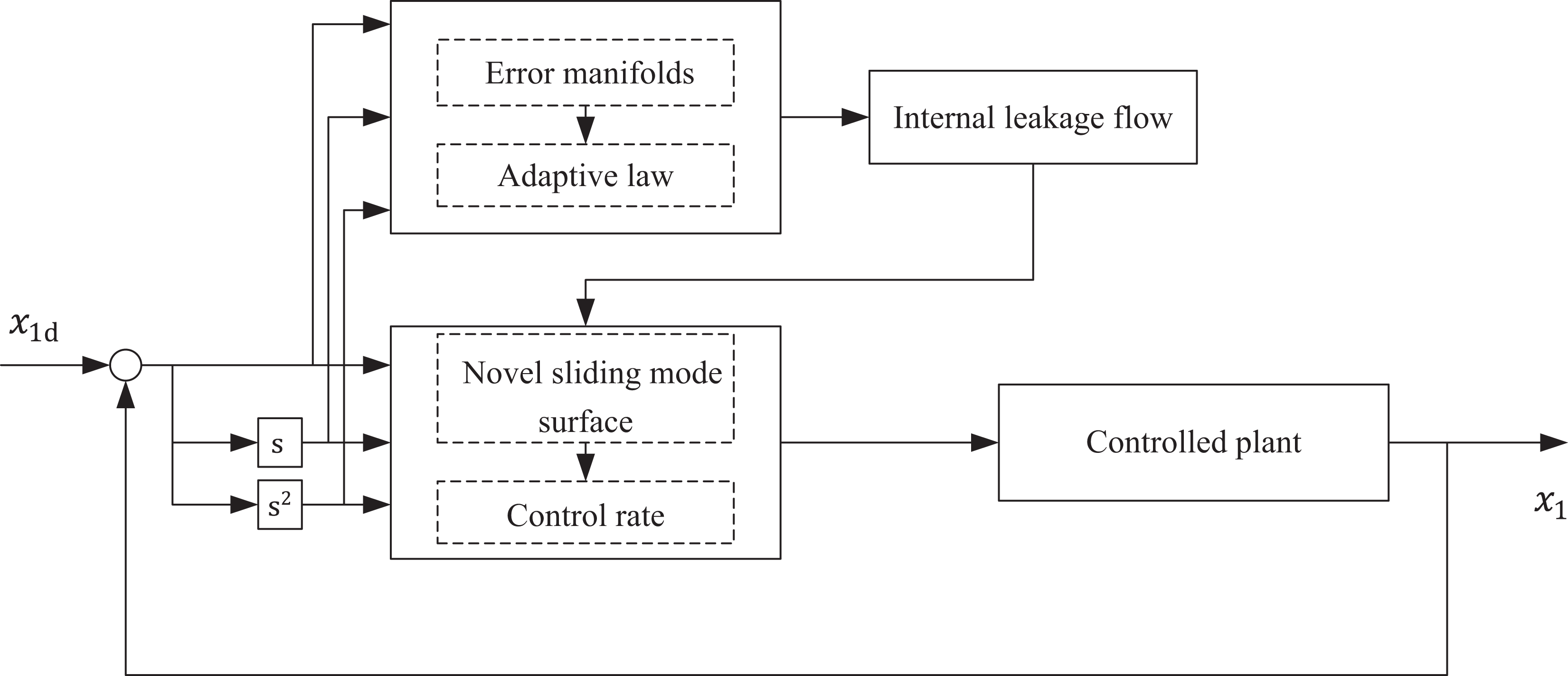
Control logic.
Stability analysis
The Lyapunov function is set to

Eq. (30) is substituted into Eq. (29)

By taking the derivative of Eq. (31) with time and substituting it into Eqs. (32) and (26), we get

where
Differentiating the Lyapunov function

When the state error variables
Experimental results
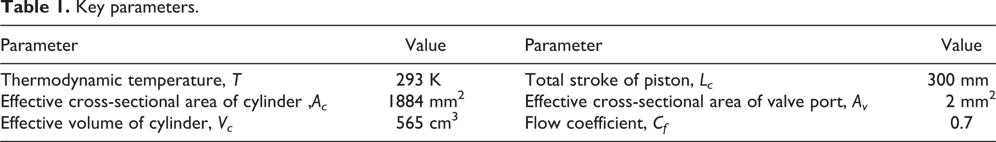
Table 1 lists the key parameters of the pneumatic three-UPU robot. The controller parameters are l = 3.6,
Key parameters.
To verify the 3D force loading performance of the pneumatic three-UPU robot controller, two sets of experiments were conducted. Furthermore, to verify the effectiveness of the control algorithm of I&I, a PID controller and sliding mode controller
26
were introduced for comparison. Two groups of 3D force loading step experiments are performed: the loading position coordinates are x = 0 mm, y = 0 mm, and z = 403.05 mm. The length of the branch chain of the robot in this position is calculated using Eq. (3): l
1 = l
2 = l
3 = 570 mm. The expected outputs of the 3D force loading are Fx
= 100 N, Fy
= 100 N, and Fz
= −10 N, and Fx
= 50 N, Fy
= 50 N, and Fz
= 110 N. According to Eq. (8), under the two sets of loading control, the expected output forces of the three cylinders are f
1 = 124.1 N, f
2 = −99.0, and f
3 = −39.2 N, and f
1 = 116.2 N, f
2 = 4.71 N, and f
3 = 34.6 N. In addition, because the robot is under the influence of its own gravity, the initial value of Fz
is approximately 51.2 N. Figures 6
to 8 show the three-axis load curves of the robot. Figure 9 shows the steady-state error of Fy
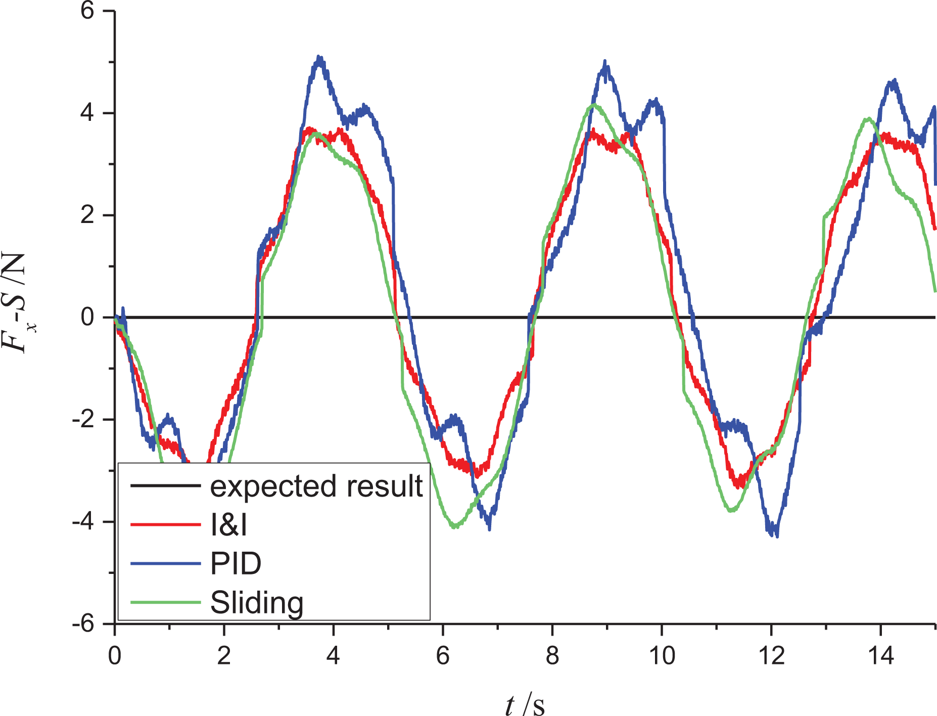
. Table 2 gives a comparison of the control performance indicators of step response 1. In the Z-axis load sine tracking experiment, the sine frequency is 0.2 Hz, and the amplitude is 60 N. The loading position coordinates are x = 0 mm, y = 0 mm, and z = 403.05 mm. The initial loads of the robot are Fx
= 0 N, Fy
= 0 N, and Fz
= 51.2 N. Figures 10
to 12 show the three-axis load curves of the robot. Figure 13 shows the Fz
error curve. Table 3 presents a comparison of the control performance indicators for sinusoidal tracking.

Comparison of step responses along the x-axis.

Comparison of step responses along the y-axis.

Comparison of step responses along the z-axis.
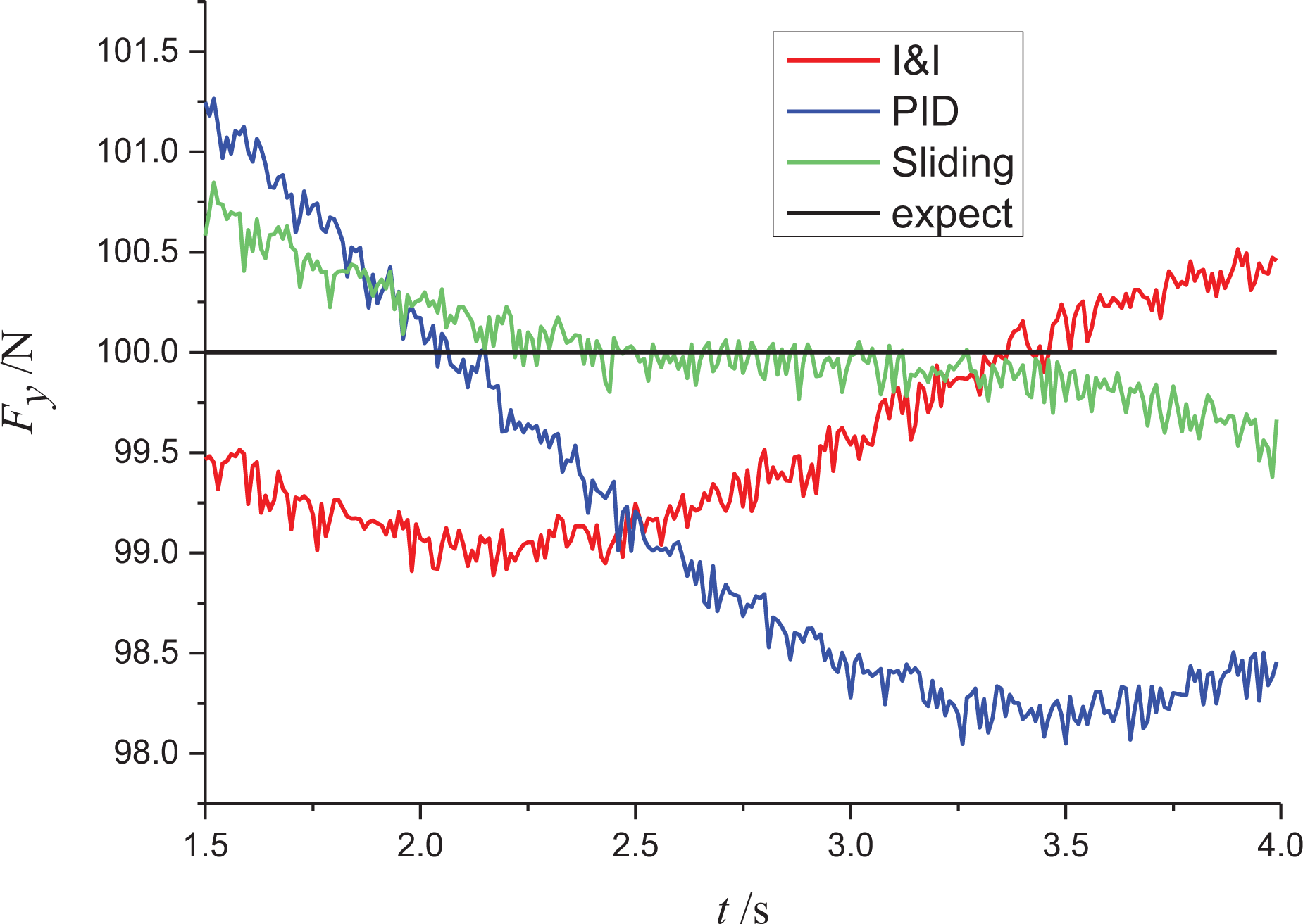
Steady-state error along the y-axis.
Comparison of step response control performance.
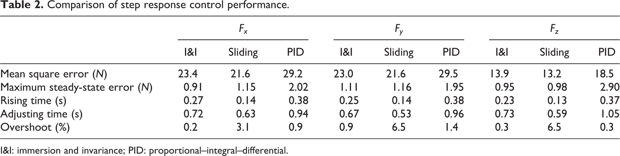
I&I: immersion and invariance; PID: proportional–integral–differential.
Comparison of sinusoidal tracking along the x-axis.

Comparison of sinusoidal tracking along the y-axis.

Comparison of sinusoidal tracking along the z-axis.

Error in sinusoidal tracking along the z-axis.
Comparison of sinusoidal tracking control performance.
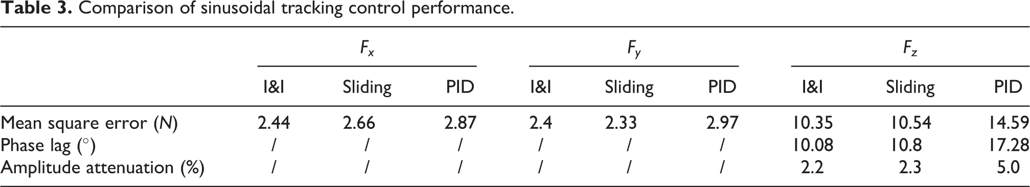
I&I: immersion and invariance; PID: proportional–integral–differential.
The experiments are conducted at the same sampling frequency of 100 Hz, and the experimental data are unfiltered.
From the experimental results, (1) compared with the PID controller, the I&I step response rising time is reduced by approximately 33% on average, and the average adjusting time is reduced by approximately 28%. Further, the maximum steady-state error is reduced by approximately 50% on average, and the mean square error is reduced by approximately 21% on average. This shows that the I&I control has higher steady-state accuracy and better dynamic performance than the PID controller. (2) According to Table 2, the I&I step response mean square error and adjusting time are close to those of the sliding controller, and the maximum steady-state error is slightly lower than that of the sliding controller. (3) Although the rising time of the sliding controller is significantly lower than that of the I&I controller, there is an obvious overshoot in the step response (the maximum overshoot is around 6.5%). This shows that although the sliding controller improves the response speed of the system to the maximum, it compromises the stability of the system. The I&I controller can improve the response speed of the system as much as possible while ensuring the stability of the system. (4) In the 0.2 Hz sinusoidal tracking test, compared with the PID controller, the mean square error of the I&I controller is approximately 10.35 N, which is 29% lower than that of the PID controller. The amplitude attenuation is approximately 2%, and the phase lag is 41% lower than that of the PID controller. Meanwhile, compared with the sliding controller, the I&I mean square error is reduced by approximately 1.4% and phase lag is reduced by 6.7%. Moreover, the amplitude attenuation is reduced by approximately 4.3%.
Conclusion
We established an ideal state equation for the 3D force loading system of a pneumatic three-UPU robot. The system is based on a metal gap-sealed cylinder driven by a proportional flow valve. We developed an accurate mathematical model for implementing the load control.
Suitable additional terms and an adaptive mechanism are designed to ensure that the error manifold exhibits invariance and attractivity. A hyperbolic tangent function is introduced in the design of the sliding mode surface to improve the smoothness and thus the stability of the error on the sliding mode surface.
The experimental results indicate that the I&I loading control algorithm responds faster than the PID controller. The steady-state and tracking errors are significantly reduced, and the control performance is improved considerably.
In future research, a dynamic scale technology can be introduced in the I&I method to further improve the convergence speed. This could help increase the adaptive ability and dynamic response-ability of the dynamic estimation errors of the parameters.
Supplemental material
Supplemental Material, sj-pdf-1-arx-10.1177_17298814211044932 - Three-dimensional loading control of a pneumatic three-universal–prismatic–universal robot
Supplemental Material, sj-pdf-1-arx-10.1177_17298814211044932 for Three-dimensional loading control of a pneumatic three-universal–prismatic–universal robot by Yu Liu, Qingling Zhu, Guoxin Zhao and Shuchao Ma in International Journal of Advanced Robotic Systems
Footnotes
Declaration of conflicting interests
The author(s) declared no potential conflicts of interest with respect to the research, authorship, and/or publication of this article.
Funding
The author(s) received no financial support for the research, authorship, and/or publication of this article.
Supplemental material
Supplemental material for this article is available online.
References
Supplementary Material
Please find the following supplemental material available below.
For Open Access articles published under a Creative Commons License, all supplemental material carries the same license as the article it is associated with.
For non-Open Access articles published, all supplemental material carries a non-exclusive license, and permission requests for re-use of supplemental material or any part of supplemental material shall be sent directly to the copyright owner as specified in the copyright notice associated with the article.