
Abstract
The tilt-rotor unmanned aerial vehicle (TRUAV) has vertical take-off and landing and high-speed flight capabilities through conversion and reconversion modes, thereby presenting wide application prospects. This article presents a compact tilt tri-rotor UAV. For flying in the conversion mode, the TRUAV needs to realize the transition of two control logic and two kinds of actuators in both of the rotor and fixed-wing modes, achieving the control of the multi-input multioutput, input nonaffine, and nonlinear multichannel cross-coupling UAV system. Furthermore, the lateral dynamics of a tilt tri-rotor UAV is more unstable for unpaired rotors. These system characteristics present a great challenge to conversion control. To solve these problems, the nonlinear dynamic model of the vehicle in the conversion mode is provided. Furthermore, a cascade control system consisting of position control, velocity control, angle control, angular velocity control, and control mixer is proposed. The simulation result of the control system shows steady flight and a fast transition in the conversion mode with modeling uncertainty in case of no wind.
Keywords
Introduction
The tilt-rotor unmanned aerial vehicle (TRUAV) has a rotor mode, fixed-wing mode, conversion mode, and reconversion mode. The conversion mode is from the rotor mode to the fixed-wing mode, as shown in Figure 1. The reconversion mode is from the fixed-wing mode to the rotor mode.

The conversion mode of the TRUAV. TRUAV: tilt-rotor unmanned aerial vehicle.
In the rotor mode, the TRUAV realizes vertical take-off and landing by the lift generated by rotors or propellers; in the fixed-wing mode, the TRUAV achieves the high-speed cruise by the lift generated by wings; the conversion mode realizes the transition between the rotor mode and fixed-wing mode through tilting of rotors or propellers. Compared with the rotor UAV, the TRUAV can be applied in scenarios, where high speed, long range, or large payload capacities are needed. Compared with the fixed-wing UAV, the TRUAV without the need of a runway can be used in scenarios such as flying in constrained or small scope areas and close-range inspection. 1
The multimode of the TRUAV poses some challenges for the flight control of the conversion mode. 1 With the rotors tilting, the speeds of rotors are higher than those in the rotor mode; the airspeed is lower than that in the fixed-wing mode and the aerodynamic efficiency of control surfaces is lower; the adjustment ability and the stability become worse. So, the energy consumption increases and the flight efficiency is lower. Generally, the conversion mode is only used as the transition between two main modes of the rotor and fixed wing. In the conversion mode, the TRUAV is a multi-input multioutput system with two kinds of actuators, however, it is overactuated in the longitude channel and underactuated in the horizontal channel, which make the convergence of lateral position hard to guarantee. Moreover, for a tilt tri-rotor UAV, the drag moment induced by the unpaired rotors aggravates the unstable lateral dynamics. In the conversion mode, the varying thrust vector makes the system input nonaffine and causes a dramatic cross-coupling effect between the attitude and height channels, which adds difficulty in the controller design. Furthermore, the control logic and actuators of the rotor and fixed-wing modes are different. In the rotor mode, the height and the forward speed are controlled by the longitudinal vertical force and pitch moment, respectively, and the corresponding actuators are rotor speeds. However, in the fixed-wing mode, the height and the forward speed are controlled by the pitch moment and forward force, respectively, and the corresponding actuators are the elevator, aileron, and rotor speeds.
To solve the control problems of the conversion mode, some control methods have been adopted. Some scholars adopted the gain scheduling. Kang et al. 2 and Yuksek et al. 3 developed gain scheduling PID controllers realizing the flight in the full modes. The duration of the conversion mode in the literature 3 was 20 s, and the amplitude of the pitch angle was from −12° to 13°. Zivan et al. 4 adopted the gain scheduling PID method realizing a full mode flight by adjusting 255 parameters of the controller, the duration of the conversion mode was less than 3 s, and the attitude fluctuated obviously when the mode switched. Since many controller parameters have to be designed, this method might be tedious and time inefficient. Many scholars adopted the dynamic inverse method to design control system. Rysdyk and Calise 5 adopted the dynamic inversion with neural network control architecture realizing the attitude and angular velocity control. Di Francesco 6 adopted cascade control, and the outer loop controlled the longitudinal velocity and height, generating inputs for the inner loop controlling attitude. Both loops used the incremental nonlinear dynamic inverse method solving the input nonaffine problem and realizing the conversion mode flight without interference, of which the duration was 40 s. Cetinsoy et al. 7 adopted cascade control, the outer loop controlled positions producing command angles and thrust, and the inner loop controlled attitude. Both loops used dynamic inversion for a small-tilt wing UAV with four-rotor configuration, and the simulation results and actual flight experiments realized a stable flight in the conversion mode, of which the duration was 10 s. Kang et al. 8 adopted cascade control, the outer loop controlled the velocity and height, and the inner loop controlled attitude. Both loops adopted dynamic inversion based on a sigma-pi neural network to design the control system, the simulation results showed the conversion mode lasted 70 s and the attitude, altitude, and position kept steady. However, Rysdyk and Calise 5 only considered the attitude control, neglecting the position control. In the conversion mode, the energy consumption increases and the anti-interference ability decreases. The conversion mode should transit quickly. The durations of the conversion in the literature 6,8 were long, which increased the flight risk and increased the energy consumption, resulting in reduced endurance. Besides, Di Francesco 6 did not consider lateral position control. Cetinsoy et al. 7 adopted four-rotor configuration, which was more laterally stable and easier for control decoupling compared with the tri-rotor configuration. Besides the two control methods above, some other control methods have been used. Yildiz et al. 9,10 adopted the model reference adaptive controller for a TRUAV with four-rotor configuration realizing decoupling control, and the experiments showed that the altitude and attitude were stable in the conversion mode. However, Yildiz et al. 9,10 neglected the aerodynamic effect of wings, ignoring the transition between two control logics and two kinds of actuators. Chang et al. 11 adopted cascade control with the outer loop for altitude, airspeed, and heading control and inner loop for attitude control, and both loops adopted the fuzzy control method. The simulation results showed the height and airspeed could track the expectations in the conversion mode and the duration was 20 s.
In terms of the control allocation, direct control allocation, 12 pseudoinverse, 13 a daisy chaining logic, 14 linear programming, 15 and quadratic programming 16 have been adopted for the UAV control. The direct inversion cannot be applied for the number of actuators and channels being not equal in the conversion mode. The linear programming or quadratic programming methods are complex calculation and difficult for realizing the precise allocation, which will aggravate multichannel coupling and increase the control error. Considering the configuration of the proposed tilt tri-rotor UAV, a control allocation method using the daisy-chaining logic for reference is more precise and less complex.
As reviewed above, some four-rotor configuration TRUAVs realized the lateral position control in the conversion mode for easy control decoupling. Considering the tilt tri-rotor UAV being underactuated in the horizontal channels, most control systems for the conversion mode only controlled attitude instead of the lateral position, which would cause the lateral position to deviate easily. In some studies, the duration of the conversion mode was long or there was obvious oscillation in attitude and height channel at the mode switching, which would aggravate the flight risk. The major contributions of this article are as follows: Aiming at the flight character of the conversion mode, the control system combines the way of rotor and fixed-wing UAV control. Different controllers and control allocation methods in low- and high-speed segments are designed for the position control, velocity control, angle control, and control mixer of the control system separately. The control system not only keeps the lateral position of the tilt tri-rotor UAV but also realizes a fast and stable flight in the conversion mode with modeling uncertainty. The control allocation method of the control mixer designed not only solves input nonaffine problem and the problem that the number of actuators is different from the number of control channels but also realizes the smooth transition between two control logics and two kinds of actuators in both of rotor and fixed-wing modes. Furthermore, the angle control, the angular velocity control, and the vehicle control realize the decoupling control with the control mixer.
The article is organized as follows. In the second section, a tilt tri-rotor UAV prototype is presented and dynamics modeling of the conversion mode is proposed. In the third section, the control system design is provided. The experiment is implemented in the fourth section. Finally, the conclusion is discussed in the fifth section.
Dynamics modeling
In this article, a compact electrically powered tilt tri-rotor UAV is shown in Figure 2.

Tilt tri-rotor UAV prototype view: (a) the rotor mode, (b) the fixed-wing mode, and (c) the conversion mode. UAV: unmanned aerial vehicle.
As shown in Figure 2, the proposed tilt tri-rotor UAV has a conventional aileron, elevator control surface configuration, three fixed-pitch rotors, and two servo motors, which are similar to TRUAV in the literature. 1 The two front rotors can tilt from pointing vertical position to pointing horizontal position using two tilting mechanisms, which are driven by two servo motors, respectively. The tail rotor is fixed at the rear of the UAV vertically. The tilt tri-rotor UAV is in the rotor mode with the front rotors in vertical position, the control logic of which is shown in Figure 3. The roll channel is in the control of the differential thrusting of two front rotors, and the pitch channel is in the control of the differential thrusting between two front rotors and the tail rotors. The yaw channel is in the control of the differential tilting of two front rotors. The height channel is controlled via the total rotor thrusts. 1 In Figure 3(c), if one of the front rotor thrusts increases and the corresponding differential angle does not change, or one of the front rotor differential angles changes and the corresponding thrust does not change, the horizontal component and the vertical component of this rotor thrust and the drag moment of this rotor will change, which would cause the cross-coupling effect: the pitch, roll, yaw, and height channels are influenced at the same time. For the four-rotor configuration, when the four rotors rotate at the same speed, the drag moment will be offset, and the other three channels can remain stable. For the tri-rotor configuration, when the differential angles of two front rotors are same, under the condition of keeping the other three channels stable, the drag moment cannot be offset resulting in yawing. The drag moment can only be offset by differential tilting, which increases the control difficulty of the horizontal channels.

Control logic in the rotor mode: (a) roll, (b) pitch, (c) yaw, and (d) height.
The TRUAV is in the fixed-wing mode with two front rotors fixed in the horizontal position and the tail rotor off. Two front rotors only offer forward thrust in this mode. The roll channel is in the control of the aileron, the pitch channel is in the control of the elevator, the speed channel is in the control of the thrusts of the rotors, and the yaw channel is in the control of the aileron with no rudder. The height channel is kept in the control of the pitch angle. 1
In the conversion mode, the proposed tilt tri-rotor UAV is controlled by both the rotor mode and fixed-wing mode control logic and actuators. Vehicle parameters and aerodynamic coefficients could be obtained by the direct measurement and the system identification method. 17 The main specifications are listed in Table 1.
Specifications of the tilt tri-rotor UAV.
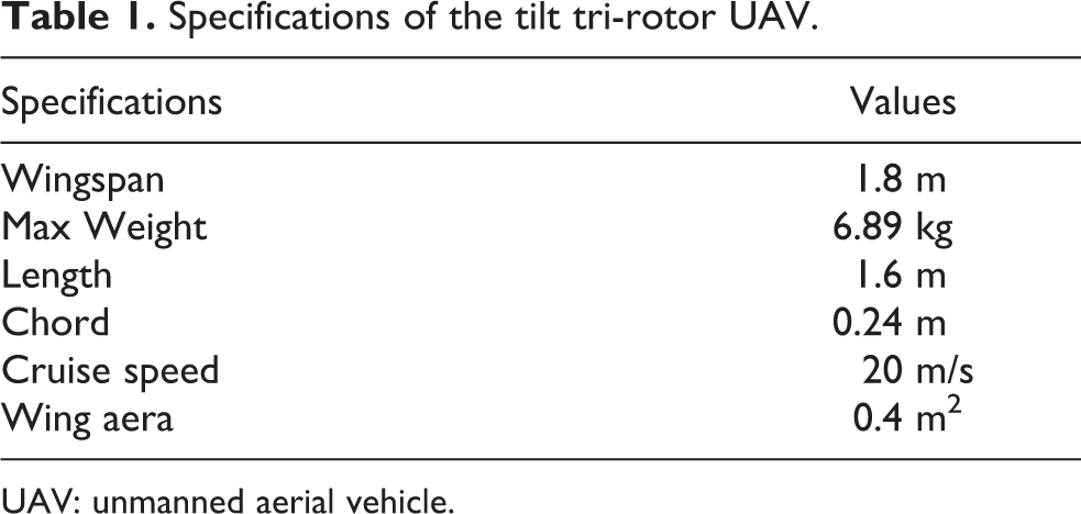
UAV: unmanned aerial vehicle.
The two referred frames shown in Figure 4 are the body frame BF(OB, XB, YB, ZB) and the geodetic frame GF(OE, XE, YE, ZE). The origin OB is the center of mass, XB points the nose of the UAV, ZB points down, and YB points the right wing. The roll, pitch, and yaw angles of the tilt tri-rotor UAV in the GF are defined as Φ, θ, and Ψ, respectively. The serial numbers of three rotors are shown in Figure 4. Rotors 1 and 3 turn counterclockwise, which are opposite to rotor 2. The tilt angles δ1 and δ2 are defined as the angles between the −ZB and motor shafts, both ranges of which are [−20°, 90°]. The positive direction of the tilt angles is pointed along XB. The rigid body dynamic equation in the BF can be described, as given in equation (1)
18
The referred frames.

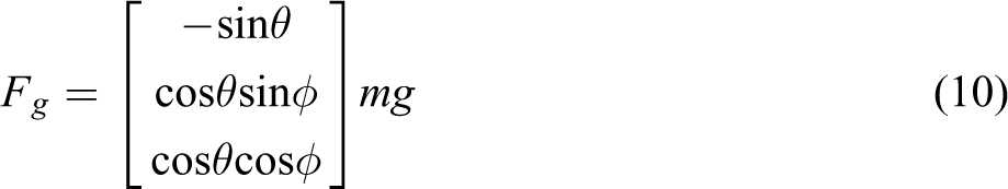
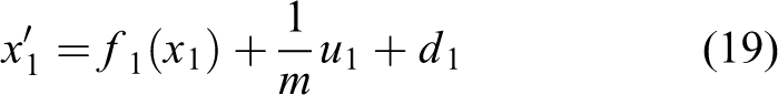
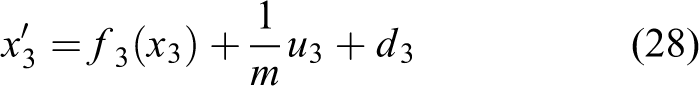
where F = [Fx, Fy, Fz]T and M = [Mx, My, Mz]T represent the sum of all externally applied force vectors applying on the center of gravity and the sum of the moment vectors defined in the BF, respectively, m represents the mass of the UAV, J is defined as the inertia matrix,

where Mgyro is the gyroscopic moment produced by the tilt rotor assemblies; Mrotate is the sum of drag moment induced by the rotor’s drag; Mthrust is the thrust moment induced by the rotors; Maero is the aerodynamic moment induced by the wings; and Mtilt is the antitilt moment induced by the tilting motion of rotors. The expressions of these are given in equations (3) to (7)

where Irotor is the inertia of the rotor assembly and

where

where


where b is the wing span,

where


where Cx, Cy, and Cz are aerodynamic force coefficients along XB, YB, and ZB separately, which are the functions of control surfaces, the stability derivatives of aerodynamic force coefficients, the control derivatives of aerodynamic force coefficients, the airspeed, and so on. 20
Control system design of the conversion mode
The control system of the conversion mode adopts the cascade control structure according to the time scale separation principle, as shown in Figure 5. The control system is composed of five nested control loops: the position control, the velocity control, the angle control, the angular velocity control, and the control mixer. Aiming at the character of the flight in the conversion mode, different controllers in low- and high-speed segments, respectively, are designed for the position control, velocity control, and angle control. The control mixer also designs different control allocation methods in low- and high-speed segments, respectively. Vswitch is the preset switching speed between the high-speed section and low-speed section. When the airspeed is larger than Vswitch, the system adopts the controller and control allocation of the high speed and vice versa.

Control system structure.
Position control design
The position control keeps the lateral position Y and the height H in the GF constant. The position control does not control the forward position X in the GF. The forward motion is realized by the control of forward velocity Vx in the GF, which is implemented in velocity control loop instead. The input of the position control is the altitude command Hc and the lateral position command Yc preset by the flight path plan.
Y channel control
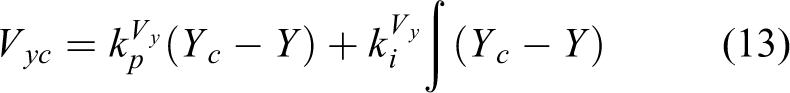
When the airspeed is low, the way of tilt tri-rotor UAV control is closer to the rotor mode, and Y channel is controlled by Vy. When the airspeed is high, the way of tilt tri-rotor UAV control is closer to the fixed-wing mode, and Y channel is controlled by
In high-speed section, Y channel adopts the nonlinear guidance logic algorithm 21 that is widely used as a fixed-wing vehicle control method. The sketch of the nonlinear guidance logic algorithm in the condition of steady and coordinated turning is shown in Figure 6.

The nonlinear guidance logic algorithm sketch.
As shown in Figure 6, point P is the way point of the flight path; d is the cross-track error; L is the distance from the UAV to P; and R is the flight radius with point O as the center of a circle. Under the condition of steady and coordinated turning, the method generates the lateral acceleration command as in GF,

In low-speed section, Y channel adopts proportion integration (PI) control to generate Vyc
where
H channel control
In high-speed section, H could be maintained by pitch angle like fixed-wing UAV. In low speed, H is usually controlled by the speed in height direction Vh like the rotor UAV. To coordinate the two control logic, the H channel adopts PI control to generate Vhc and

where

where
Velocity control design
The outputs Vyc and Vhc of the position control and the forward velocity Vxc are used as input of the velocity control. Vxc is generated by plan. In the conversion mode, the final forward target speed is cruising speed Vf of the fixed-wing mode and the forward velocity command Vxc is planned as in equation

where t0 is the start time of the conversion mode. The velocity control is in progress in the BF, and the velocity commands in the GF should be converted into the ones in the BF

where c and s are defined as cos() and sin(), respectively, and uc, vc, and wc are the velocity commands in the BF.
In low-speed segment
The velocity is controlled by [Fx, Fz,
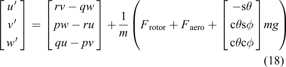
As shown in equation (18), considering
where
Set the sliding mode surface as

where x1c = [uc, vc, wc]T. The controller based on reaching law 22 is designed as

where the control parameters

Let Lyapunov function

The stability of the controller is proved. In practice, replace function sgn with function sat to reduce chattering 21

The design of k1 and

In high-speed segment
In high-speed segment, because the Y channel adopts the nonlinear guidance method to generate
The design process of u and w channel controllers is similar to that in the low-speed segment. The dynamics of u and w channels in BF should be

where Frotorx and Frotorz are the x and z components of Frotor. Considering
where

where

where the control parameters

The proving process of the controller stability is the same as in equation (23). Fx and Fz are expressed as

Angle control design
In low-speed segment
The angle control adopts P control

where
In high-speed segment
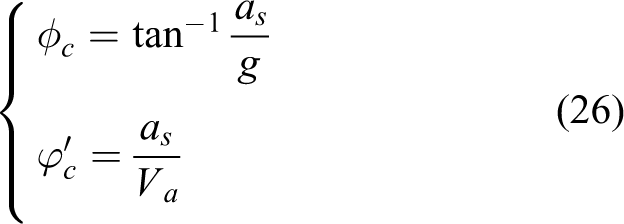
In high-speed segment, the nonlinear guidance method generates rc instead of control
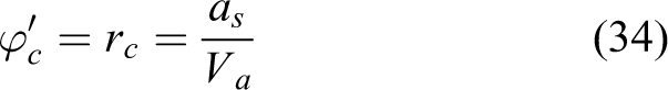
The other two channels adopt P control in the conversion mode as equation (33).
Angular velocity control design
The angular velocity control makes angular velocities track the commands and outputs virtual control moments. The angular velocity dynamics equation is the second one of equation (1), which could be represented as

where

where x2c = [pc, qc, rc]T; s2 = x2c−x2;
Control mixer design
As given in Table 2, Va is controlled by Fx and My in the fixed-wing mode and rotor mode, respectively, and H is controlled by the My and Fz in the fixed-wing mode and rotor mode, respectively.
The control logics and actuators in fixed-wing mode and rotor mode.

In the conversion mode, the control mixer allocates all the virtual control commands of the fixed-wing and rotor mode

where kf is the weight. kf is from 0 to 1, realizing the transition from rotor thrusts to control surfaces in the conversion mode. When the gravity and the aerodynamic lift balance, Fz converges to 0 gradually, and H and Va are controlled by My and Fx, respectively, thereby achieving the transition from [Fz, Mx, My, Mz] T to [Fx, Mx, My, Mz]T.
In low-speed segment
With tilt angles having a gradual change, Mgyro, Maero, and Mtilt are small and therefore taken as disturbance. To solve input nonaffine problem caused by tilt angles, the variable substitution method is adopted
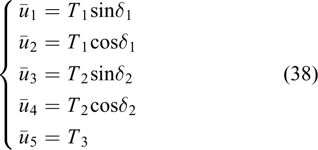
where
with equations (38), (39), (2), (4), (5), and (9),

So, with equations from (38) to (40)

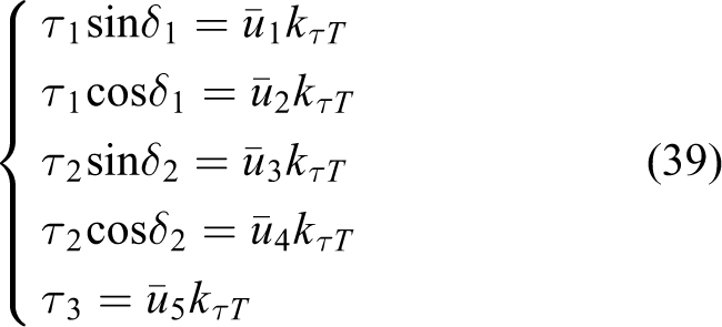
In high-speed segment
Mgyro and Mtilt are considered as disturbance. First, the fixed-wing actuators
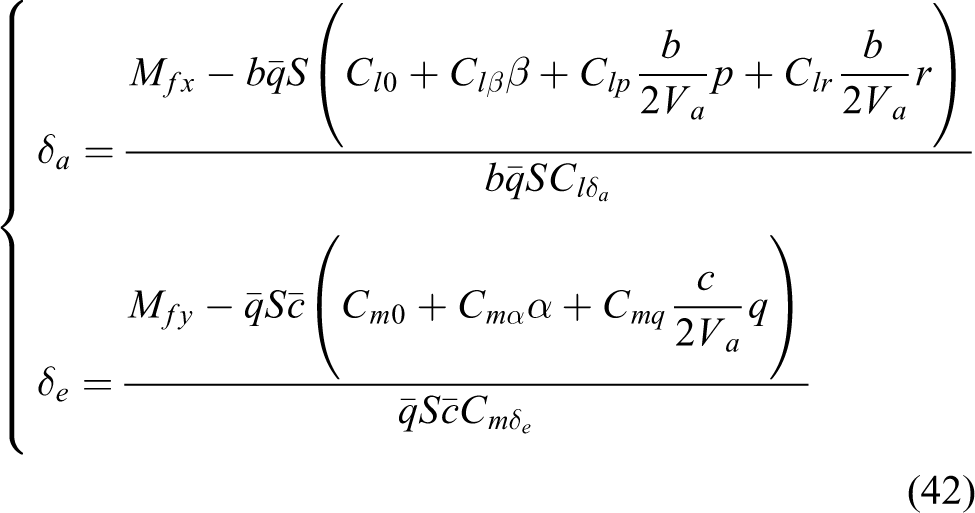
If the control surfaces are saturated, Mfx and Mfy should be calculated as equation (43)

where
Use equations (38)
to (41) to allocate remaining virtual control command [Fx−Ffx, Fz−Ffz, Mx−Mfx, My−Mfy, Mz−Mfz]T to
Simulation experiment
The experiment is carried out without wind in the Simulink simulation environment. The disturbance consists of 10% aerodynamic modeling uncertainty and 10% moments of inertia uncertainty. The conversion mode flight experiment is carried out, as shown in Figure 7.

The path of the flight experiment.
The tilt tri-rotor UAV takes off from point H in the rotor mode and then rises vertically at a fixed speed. The tilt tri-rotor UAV keeps hovering once reaching point 1 of 10 m. When the UAV is stable, the tilt tri-rotor UAV begins the conversion mode. In the conversion mode, the UAV keeps a fixed altitude along a flight straight path. The termination condition of the conversion mode is

where

Position and airspeed in conversion mode: (a) h, (b) local graph of h, (c) Va, and (d) Y.

The angle and angular velocity in conversion mode: (a) roll angle, (b) pitch angle, (c) yaw angle, (d) p, (e) q, and (f) r.

Actuators in conversion mode: (a) tilt angles, (b) rotor speeds, and (c) control surfaces.
As shown in Figure 8, after the UAV rising to the target altitude of 10 m, the UAV enters the conversion mode. The duration of the conversion mode is less than 8 s, which is less than 70 s of the literature,
8
40 s of the literature,
6
and 20 s of the literature.
11
In the conversion mode, H keeps steady, the maximum deviation of H is less than 0.12 m. When entering the fixed-wing mode, there is a deviation of 0.4 m in H channel because the control logic and control allocation change. The deviation reduces fast in the fixed-wing mode. In the conversion mode, the deviation of Y increases to 0.012 m and then converges less than 0.002 m, which verifies the effectiveness of lateral position control. The maximum deviation of Y is caused by the same reason as H, and the deviation of Y could converge in the fixed-wing mode. Va increases steadily and there is an overshoot for that tilt angles do not reach
As shown in Figure 9, because there is cross-coupling effect and the tilt tri-rotor UAV is underactuated in the horizontal channel,
As shown in Figure 10, all the actuators change smoothly without saturation and achieve a smooth transition during the conversion mode. There is an oscillation of tilt angles at 9.5 s due to that control surfaces take effect. The two tilt angles increase to 80° and 82° steadily. The rotor speeds change smoothly and the tail rotor speed decreases to 0 gradually until the mode enters the fixed-wing mode.
Because the control system adopts the cascade control structure according to the time scale separation principle and there are no parameters in the control mixer, the control parameters of each loop can be adjusted according to the order of angular velocity, attitude, velocity, and position, realizing the parameter setting of the control system. Angular velocity control has six control parameters,
Conclusion
In this article, a compact tilt tri-rotor UAV is proposed, the dynamic model of which in the conversion mode is established. To solve the conversion control problems, a cascade control system consisting of the position control, velocity control, angle control, angular velocity control, and control mixer is designed for the proposed tilt tri-rotor UAV. Aiming at the flight character of the conversion mode, the control system is designed to include different controllers and control allocation methods in low- and high-speed segments, respectively. The control system can not only keep lateral position and solve input nonaffine problems but also can realize the smooth transition between two control logics and two kinds of actuators in both of the rotor and fixed-wing modes by adjusting the weight coefficient, which is a function of airspeed. Moreover, the controllers realize the decoupling control of multichannel cross coupling system with the control mixer. The conversion flight with modeling uncertainty experiment shows that the duration is short, the positions and the attitude are stable, all the actuators change smoothly without saturation, which demonstrates the effectiveness of the control system.
This article focuses on solving the conversion mode basic control problems neglecting wind influence. When there is external interference such as gust disturbance, the stability of the control system designed decreases. The disturbance observer will be added to the existing control system in future research to solve the problem of wind rejection and enhance the robustness. Moreover, the reconversion mode control problems will be considered in future research.
Footnotes
Declaration of conflicting interests
The author(s) declared no potential conflicts of interest with respect to the research, authorship, and/or publication of this article.
Funding
The author(s) received no financial support for the research, authorship, and/or publication of this article.
Nomenclature

| u, v, w | Three velocities in body frame |
| p, q, r | Three angular velocities in body frame |
| Φ, θ, Ψ | Roll angle, pitch angle, and yaw angle |
| δe, δa | Control quantity of elevator and aileron |
| δ1, δ2 | The tilt angles |
| Speed of the i’th rotor | |
| , Ti | The i’th rotor’s drag moment, and thrust |
| , Fg, | The aerodynamic force, the gravity, the rotor thrust |
| Mgyro, Mrotate, Mthrust, Maero, Mtilt | Gyroscopic moment, sum of drag moment, thrust moment, aerodynamic moment, and antitilt moment |