
Abstract
For spatial multibody systems, the dynamic equations of multibody systems with compound clearance joints have a high level of nonlinearity. The coupling between different types of clearance joints may lead to abundant dynamic behavior. At present, the dynamic response analysis of the spatial parallel mechanism considering the three-dimensional (3D) compound clearance joint has not been reported. This work proposes a modeling method to investigate the influence of the 3D compound clearance joint on the dynamics characteristics of the spatial parallel mechanism. For this purpose, 3D kinematic models of spherical clearance joint and revolute joint with radial and axial clearances are derived. Contact force is described as normal contact and tangential friction and later introduced into the nonlinear dynamics model, which is established by the Lagrange multiplier technique and Jacobian of constraint matrix. The influences of compound clearance joint and initial misalignment of bearing axes on the system are analyzed. Furthermore, validation of dynamics model is evaluated by ADAMS and Newton–Euler method. This work provides an essential theoretical basis for studying the influences of 3D clearance joints on dynamic responses and nonlinear behavior of parallel mechanisms.
Introduction
Robots are becoming an indispensable part of modern industry and are playing an increasingly important role. 1,2 For some reasons, such as manufacturing tolerance, assembling errors, and wear phenomenon of the kinematic joints, clearance always exists in kinematics joints, and the performance of the robot is unsatisfactory. 3 –5 Planarization of spatial clearance joints has limitations in studying the dynamics behavior for mechanical systems because the complex motion mechanism of spatial clearance joints is neglected. Moreover, frequent contact and collision events are the source of nonlinearity. It may exhibit chaotic responses under certain conditions and even affect the overall dynamic behaviors of the system.
Over the past decades, issues related to clearance joint in mechanism dynamics have been a hot topic. 6 It is noteworthy that most of the research were mainly associated with the issue of plane system. However, dynamics research of multi-degrees-of-freedom (DOF) spatial systems considering 3D compound clearance joint has not been reported as far as we know. Yu et al. 7 eliminated redundant constraints of an overconstrained mechanism and further investigated the dynamics model and performances of the system considering multiple revolute clearance joints. Zhan et al. 8 modeled joint clearance parameters as interval variables and provided fresh ideas for studying motion reliability of 3-RRR parallel manipulators considering joint clearances. Li et al. 9 built a rigid-flexible coupling dynamic model to analyze the dynamics behavior of solar array. A rigid frame and flexible parts are described by nodal coordinate formulation and absolute nodal coordinate formulation frames, respectively. Zheng et al. 10 developed a modeling technique based on nonsmooth dynamic method and have studied the effect of stiction on the dynamic response. Zhao et al. 11 presented a modeling approach of a piston skirt–liner system with lubricated pairs and evaluated lubrication and dynamic performances of the mechanism. It is worth mentioning that the above work takes into account different factors and provides ideas for establishing an accurate dynamic model with clearance joints. Different from the previous method, Ordiz et al. 12 used Simscape to model the industrial press. Then, ANSYS was used for stress analysis to explore the impact of clearance evolution on service life of the machines. Wu et al. 13 studied the nonlinear characteristics of a crank-slider mechanism with multiple clearance joints through correlation dimensions. Ambrósio and Pombo 14 and Marques et al. 15 improved pre-existing dynamic modeling methods of the mechanisms containing clearance joint, respectively. Both of these methods simplify the modeling process and improve modeling efficiency.
The above literature works only for planar systems. However, it is necessary to consider 3D models of the system in some cases. Erkaya 16 investigated the influence of spherical clearance joints and flexible joint connection on the vibration of linkage by experiment and numerical simulation. Chen and Sun 17 established a dynamics model of parallel mechanism containing spherical clearance pair. The clearance model in the above article has been extended to three dimensions, and the established dynamic model is more accurate than the plane model. However, the effect of revolute clearance pair is ignored. Using nonsmooth modeling method, Cavalieri and Cardona 18 developed a 3D model of revolute pair, in which axial clearance is neglected. Yan et al. 19 validated the existence of 3D revolute pair with clearance through experiments. They verified correctness of the proposed model, which can describe the axial and radial clearance. Tian et al. 20 investigated the influences of lubrication cylindrical joint and flexibility component on dynamics responses of crank-slider system. Then, Liu et al. 21 developed a four-point model to detect the contact between cylinder elements. Flores et al. 22 deducted a kinematic model for revolute clearance joints. They carried out numerical simulations on the double pendulum mechanism. A new enhanced formulation was recently developed by Marques et al. 23 to simulate axial and radial contact of the revolute clearance joint. The simulation results show that it is necessary to consider radial and axial clearances in dynamic modeling process. Subsequently, Marques et al. 24 considered different friction models and explored the dynamic response of the RSSR mechanism. As can be seen from the above literature, many scholars have developed different 3D clearance joint frames for application in different fields and have achieved good results.
For multibody systems, to reveal dynamics behavior of the system more accurately and truthfully, various types of clearance joints should be considered in the dynamic model. In this article, a motion frame of 3D revolute clearance joint is proposed. A dynamics modeling method of parallel mechanism considering 3D compound clearance joint is given. The influence of the compound clearance joint on the dynamic response of the spatial parallel mechanism is discussed. Furthermore, evaluating influences of clearance joint on output responses are all prerequisites for analysis, design, optimization, and control of nonlinear systems. The purposes of the article are to analyze the influences of 3D compound clearance joint on dynamics responses of parallel mechanisms.
The structure of the remainder of this article is as follows: The second section provides a mathematical description of the 3D revolute clearance joint and 3D spherical clearance joint, including kinematics model and contact force model. Nonlinear dynamics model of the parallel mechanism with 3D revolute clearance joint and spherical clearance joint is presented in the third section. A computational procedure for the dynamic model is also presented in this section. In the fourth section, influences of compound clearance joint and axis misalignment on system response are explored, and dynamics model is verified by ADAMS and Newton–Euler method, respectively. Salient conclusions are presented in the fifth section.
Model for 3D clearances joints of parallel mechanism
Mathematical description for 3D spherical clearance joint
Introduction of clearance into a spherical pair released three kinematic restrictions, which can be shown in Figure 1. It is generally considered that only one contact form, point contact, exists in dynamic simulation modeling because of its structural reasons. The geometric centers of the two elements (socket and ball) of the spherical joint are expressed as si
and bj
. Vectors

The 3D spherical clearance joint.
The clearance of the spherical joint can be described as

The vector of eccentricity

Relative penetration depth is written as

Mathematical description for 3D revolute clearance joint
For idea revolute pair, the axis of journal and bearing always keep in coincidence during joint movement. However, when the robot is connected by the joint, clearance inevitably exists. In that case, axis misalignment may occur in the clearance joint. This results in different joint element configurations, namely, no contact, point contact, line contact, and plane contact. The above contact conditions can be considered as a combination of independent axial and radial contact conditions. The schematic diagram of four contact configurations can be found in other scholars’ work. 19,22,23 A 3D revolute clearance joint is shown in Figure 2, and it consists of bearing and journal. The radius of the journal is Rjo . Rb 1 and Rb 2 are the inner and outer radii of bearing, respectively. Lj and Lb denote the length of journal and bearing, respectively.
The 3D revolute clearance joint.
The axial and radial clearances can be defined as

For dealing with point contact, the contact impact detection of 3D revolute clearance joint can be regarded as the contact impact detection problem of two impact rings located at the top and bottom of bearing. Therefore, as shown in Figure 3, four potential contact points are located in the top impact ring, where Pb
and Pj
are used to detect contact between bearing top surface and journal flange, Mb
and Mj
are used to detect the impact between bearing inner wall and journal. Similarly, the four potential contact points corresponding to the bottom impact ring are Qb
and Qj
, Nb
and Nj
, respectively. Centers of journal and bearing are oj
and ob
, respectively. JT
and BT
are the centers of the top surface of journal and bearing, respectively. Unit vectors
Radial contact diagram: (a) Top impact ring, (b) bottom impact ring, and (c) top view.
Position vectors of JT and BT can be given by

where
The angle between journal flange and bearing is ζ, and the angle between vector

The location vector of contact point Mb of bearing can be written as
Relative penetration depth

The position of potential contact point Mj can be obtained by combining equations (7) and (8)

For the opposite sides of contact state, the analysis process is similar.
Figure 4 shows the schematic of axial contact state. It should be noted that potential contact points of axial contact and radial contact are not necessarily in the same plane. However, the position of potential axial contact is always related to

Axial contact diagram.
The potential contact point at bearing top surface and the corresponding potential contact point on the journal flange are Pb and Pj , respectively. Their corresponding position vectors can be written as

where

The analysis of contact states occurring in the bottom surface of bearing and journal flange is similar to the analysis above.
The above analysis is about point contact cases. When bearing and journal are parallel to each other, ζ = ξ = 0, the line contact state may occur in the radial direction, and the plane contact state may occur in the axial direction. This is a particular case of the above deduction.
Calculation of contact force for clearances joints
With the motion of clearance joint, contact-impact events frequently occur at clearance joints. An appropriate contact force model is a vital part of restoring the dynamic behavior of kinematic pair and predicting global dynamics behaviors of the mechanism.
L-N continuous contact force model based on Hertz contact law is widely employed to describe normal contact force of contact-impact events. Dissipation term is introduced to reflect the energy dissipation in the contact process. 9,19,21 In this article, L-N model 25 is employed to describe normal contact force of clearance joints in point contact state

where the first term
For the radial contact between two cylinders in a parallel state, based on Hertz pressure distribution, nonlinear models such as Johnson model, Radzimovsky model, and Goldsmith model have been developed.
26
These models are implicit functions that require numerical iteration to evaluate contact forces without explaining energy dissipation. It is noteworthy that point contact and line contact on the revolute joint does not have the same contact stiffness as in a spherical clearance joint in a real scenario, since they have different topologies. To simplify the calculation, this work adopts an approximate strategy. Hence, equation (12) is used to describe the relationship between force and penetration of line contact state.
23,27
The exponent n ranges from 1 to 3/2. A more general relation, equation (13), is used to describe normal contact force

where
Friction is a commonplace event in which the direction is relative to the direction of motion of two objects. Many friction models were developed to describe the friction phenomena reasonably. Coulomb friction model, one of the most classical models, is expressed as a function of normal force and relative tangential velocity. However, some drawbacks also limit the application of the model, such as discontinuity around zero velocity, neglecting Stribeck effect and viscous characteristics. After that, some bristle-based friction models have been reported. 28 –31 These models can describe some complex phenomena such as microsliding but usually lead to inefficiency and introduce additional parameters that are difficult to identify. In this work, a continuous velocity-based friction model 32 is utilized to assess tangential friction force at the contact surface of clearance joint. This model can describe static, dynamic, and viscous friction phenomena without increasing computational time. 33,34 It has continuity and differentiability and is suitable for control and multibody system simulation, which can be written as

where vt denotes relative tangential velocity between contact elements, vs is transition velocity, μs and μk are the static and dynamic friction coefficients.
Contact force and moment of potential contact point acting on bearing are given by

where
Detection of the instant of contact is correlated with the penetration depth of two discrete integration steps tn and tn+1 . It has also been reported in other literature. 9,17,21 Once the collision is detected, contact force should be added to motion equation of multibody system as an external force. Here, note that the normal force does not produce torque. The friction torque acting on the clearance joint should be calculated according to equation (15).
Dynamics model of parallel mechanism with two type clearance joints
Figure 5 shows a 4-U

Kinematic sketch of 4-U
Geometrical and mass properties of 4-UPS/R

As illustrated in Figure 5, global coordinate frame
The position and orientation of active components are parameterized by variable

where
Rotation matrix from local coordinate frames
Universal joint allows relative rotation along perpendicular axes. The kinematic constraint can be written in the form

where
Prismatic joint, as the actuated joint, allows relative translational along the joint axis. In this mechanism, the constraint equation is defined as

where the unit vectors
The kinematic constraint of the perfect revolute joint can be written as

where
Kinematic constraints of the perfect spherical joint can be expressed as
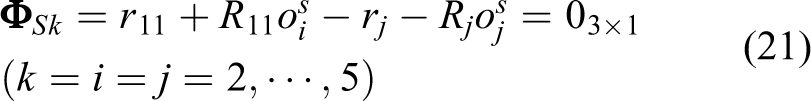
where
Driving constraint equation of five variable length kinematic chains can be given by

where
In this work, the revolute joint (R 1) and spherical joint (S 1)are assumed to be clearance joints, and then, they impose no kinematic constraints. Hence, they do not contribute to the overall constraint equation of the mechanism. Combining equations (18) to (22), one obtains an expression for constraint equations of the system as

As the numerical iteration progresses, the accumulation of numerical errors will lead to violation of constraint and even nonconvergence of results. Based on the principle of feedback control, Baumgarte’s approach
35
controls the numerical error by modifying acceleration constraint equations. Dynamics equation for 4-U

where
The computational methodologies for solving the dynamic equations of the mechanism considering both the 3D revolute clearance joint and 3D spherical clearance joint are shown in Figure 6.

The computational strategy for dynamic equations.
Dynamics response analysis of parallel mechanisms with two types of clearance joints
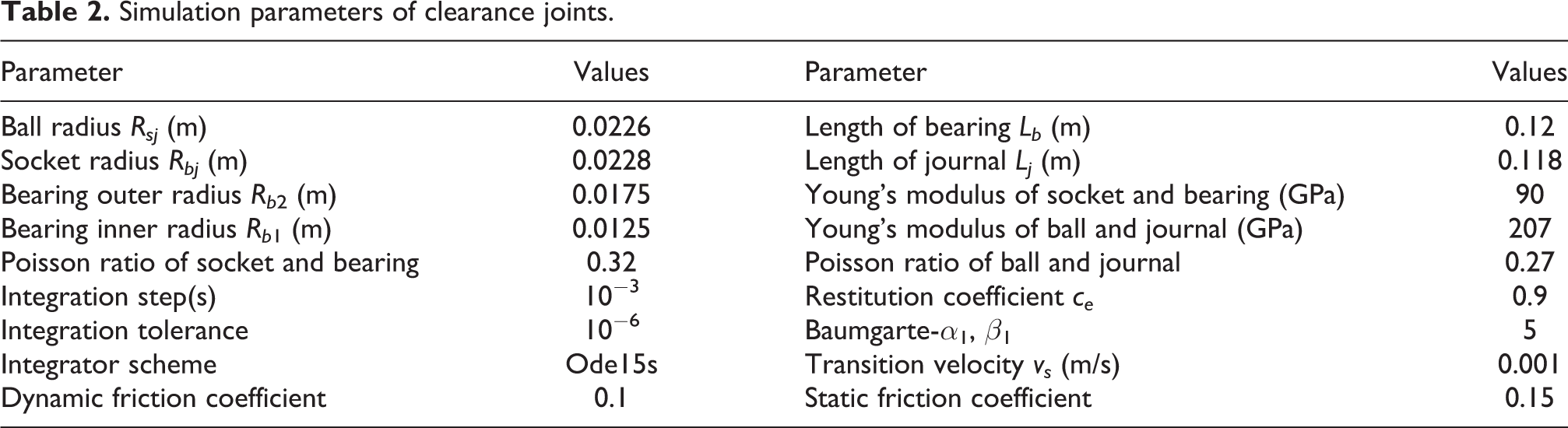
In this section, the numerical simulation results of the mechanism considering the 3D revolute clearance joint and 3D spherical clearance joint are analyzed. Simulation parameters of clearance joints are presented in Table 2. Initial positions and velocities of each component are deduced by kinematics analysis of this mechanism. The effect of initial axis misalignment of the 3D revolute clearance joint on dynamic response is assessed by comparing the two cases. In the first case, axis of journal and bearing coincides, and in the second case, the axis misalignment occurs at the initial moment, that is, the bearing rotated 0.035° clockwise around coordinate axis x 6. The motion trajectory of end actuator is defined as (unit: s, m)

Simulation parameters of clearance joints.
As shown in Figures 7 and 8, the dynamic behavior at the 3D spherical and revolute clearance joints is given in preparation for the following analysis of global dynamic behavior of the parallel mechanism. Figure 7(a) and (b) shows center trajectory diagram of spherical joint and the corresponding time history diagram. The difference in the initial conditions (axis alignment and axis misalignment) caused the center trajectories not to coincide before 0.515 s. The system gradually stabilizes as it enters the continuous contact state (the trajectories are both concentrated in the rectangular area in Figure 7(a)). From the second cycle, the time history diagram of the two trajectories basically coincides. Besides, in the case of initial alignment, the spherical joint does not move in the Z direction, as shown in Figure 7(b). Figure 7(c) shows center trajectories of bearing relative to journal with initial axis alignment. Combining with Figure 7(d), it can be observed that center trajectory of top and bottom coincides basically. Figure 7(e) and (f) are center trajectory and time history diagrams in the case of initial axis misalignment. Unlike initial axis alignment, there are apparent differences between the top and bottom center trajectories, which continue until 0.515 s, especially in the Y direction. Contact forces of clearance joints are shown in Figure 8(a) and (b). Considering misalignment of axis, contact force of high amplitude appears in the initial stage. When the system enters the stable stage, gravity plays a dominant role. The contact forces of clearance joints are in a continuous contact state. In the stable stage, the collision time of the revolute is comparatively consistent with that of the spherical joint, the two clearance joints are at the upper and lower ends of the same kinematic branch, and the peak contact force of revolute joint is less than that of spherical joint. Driving force curves for prismatic actuators considering initial axis alignment and misalignment are shown in Figure 8(c) and (d). The maximum values of driving force are related to the transient response. When considering axis misalignment, the peak values of the driving forces are higher than the case of axis alignment. Affected by the contact impact, oscillation positions of driving force curves have been aligned to the contact force curves.

Dynamic behavior at clearance joint. (a) Center trajectory in spherical joint, (b) time history diagram in spherical joint, (c) center trajectory in revolute joint with initial axis alignment, (d) time history diagram in revolute joint with initial axis alignment, (e) center trajectory in revolute joint with initial axis alignment, and (f) time history diagram in revolute joint with initial axis misalignment.

Contact force and driving force. (a) Contact force at spherical joint, (b) contact force at revolute joint, (c) driving force with initial axis alignment, and (d) driving force with initial axis misalignment.
The enormous contact force at the initial stage is related to the initial conditions. For multibody dynamics systems with clearance joint, the initial stage response depends on the initial configuration and is transient. It can be observed that the contact force generated by the initial misalignment of the bearing axis is much greater than the initial alignment. The collision phenomenon described based on the penalty method takes extremely short. The forced displacement caused by the driving will cause a larger contact force. After the system enters a stable state, the contact force level returned to normal. Therefore, in dynamic analysis, the response after the initial transient stage is often more concerned. For example, in the literature, 16,36 –38 the initial transient response is filtered.
Next, ADAMS was used to verify the dynamic model. The virtual prototype model is imported into ADAMS and then materials are assigned to each component. Fixed platform is connected to the ground by a fixed joint. Four universal joints are added to the fixed platform according to the joint distribution angle. As shown in Figure 5, the ideal spherical joints and prismatic joints are added to the moving platform and kinematic branch chains, respectively. The joint motions of prismatic joint are selected as translational. Create a cylindrical journal and a cylindrical bearing at the revolute clearance joint and add them to the fixed platform and the RP branch, respectively. The contact type is defined as cylinder to cylinder. Similarly, two balls with different radii are added to the PS branch chain and moving platform. The contact type is defined as sphere to sphere. Normal force and tangential force are defined as impact and Coulomb, and set the same simulation parameters as in the article. From the analysis of Figures 7 and 8, results indicated that initial axis misalignment only greatly impacts the initial stage. Therefore, axis alignment is considered in ADAMS model. From the observations in Figure 9(a) and (b), the compound clearance joint effect on the vibrational levels of displacement curves is inconspicuous. However, as shown in Figure 9(c) to (f), the velocity and acceleration curves of the moving platform fluctuate significantly. These fluctuations occur almost simultaneously with contact at clearance joints.

Dynamic responses of end effectors: (a) X-displacement, (b) Y-displacement, (c) X-velocity, (d) Y-velocity, (e) X-acceleration, and (f) Y-acceleration.
Compared with numerical simulation results, the curve of ADAMS has little difference in fluctuation degree and amplitude, and the vibration is more severe in Y direction, as displayed in Figure 9(c) and (d). From the acceleration curves (Figure 9(e) and (f)), it can be seen that there are several large fluctuations due to them is an alignment of the axis, which is also supported by contact force curve. The contact impact at the clearance joint is transmitted to the end effector, which can cause a high-frequency response of acceleration, and further to induce velocity fluctuations. It ultimately leads to a decrease in positioning accuracy. In short, clearance will bring a series of adverse effects, such as high-frequency vibration and low positioning accuracy. In this article, the dynamic model of 4-U
The dynamic model of the 4-U

Comparison of results between Newton–Euler method and Lagrange multiplier technique. (a) X-displacement and (b) Y-displacement.
Conclusions
As an essential nonlinear source, the contact phenomenon of clearance joint brings abundant dynamic behaviors to the system. The influences of the compound clearance joint on the dynamic responses of the system have received little attention in the previous studies. The kinematics models of 3D spherical joint and revolute joint with axial and radial clearances are established to this end. According to different contact conditions, the corresponding normal contact force model is provided. The friction phenomena between contact elements are described by a continuous velocity-based friction model. The dynamics model of the parallel mechanism is derived using Lagrange multiplier technique and Baumgarte stabilization method. The compound clearance joint and the contact forces are embedded in the dynamics model within the framework of multibody dynamics. The effect of compound clearance on the end effector is mainly reflected in the speed and acceleration response. The initial misalignment of the bearing axis contributes to the large contact force of the transient response and has little effect on the subsequent time history diagram. From our results, this method can effectively analyze the dynamic response of parallel mechanisms with various types of clearance joints and study the effect of compound clearance on parallel mechanisms. This work is of great significance to the structural design and performance optimization of the parallel mechanism. However, the work should further consider the influence of components’ flexibility and temperature on the system to expand its application to more industrial robots.
Nomenclature
Footnotes
Declaration of conflicting interests
The author(s) declared no potential conflicts of interest with respect to the research, authorship, and/or publication of this article.
Funding
The author(s) disclosed receipt of the following financial support for the research, authorship, and/or publication of this article: This work was supported by Shandong Key Research and Development Public Welfare Program [Grant No. 2019GGX104011] and Natural Science Foundation of Shandong Province [Grant No. ZR2017MEE066].