
Abstract
The parallel mechanism has advantages of the high speed, high precision, strong carrying capacity, and high structural rigidity. Most of the previous studies concerning the dynamic modeling focused on planar mechanisms with revolute clearance joints or spatial mechanisms with one spherical joint clearance, while few studies focused on spatial parallel mechanisms with multi-spherical joint clearances. In this article, a general dynamic modeling method for spatial parallel mechanism with multi-spherical joint clearances based on Lagrange multiplier method is proposed. Taking 4universal joint-prismatic joint-spherical joint/universal joint-prismatic joint- universal joint (4UPS-UPU) spatial parallel mechanism as an example, the constraint equations of common kinematic pairs in spatial parallel mechanism, such as universal joint, spherical joint, and prismatic joint, are derived in detail. The dynamic model of the parallel mechanism with two spherical joint clearances combining the Flores contact force model and the LuGre friction model is established. The correctness of model has also been verified by comparing the analysis results of MATLAB with those of ADAMS. It can be seen that dynamic model of spatial parallel mechanism with multi-spherical joint clearances could be easily established by this method, which provides a theoretical reference to establish the dynamic model of other parallel mechanism with multi-clearance in the future.
Keywords
Instruction
Compared with series mechanism, parallel mechanism has advantages of the high speed, high precision, strong carrying capacity, and high structural rigidity. 1 –6 Due to the closed-loop structure characteristics of the parallel mechanism, the dynamic model of the mechanism is usually more complicated. 7 In practical working conditions, joint clearance is unavoidable in parallel mechanism due to various reasons such as design, assembly process, friction, and wear. 8 The existence of clearance will cause vibration and noise of the mechanism to a large extent, which reduces accuracy, intensifies wear, and shortens service life of parallel mechanism. Therefore, the research on parallel mechanism with joint clearances must be considered, and how to improve the efficiency of the dynamic modeling with clearances becomes a research hotspot.
In recent years, many scholars have done a great deal of studies on dynamics model of mechanism and adopted many modeling methods. 9,10 The dynamic modeling methods mainly include Lagrange multiplier method, Lagrange equation of second kind, the Newton–Euler method, the virtual-work approach, the Kane method, and so on. Marques et al. 11 proposed a comprehensive and general method to eliminate constraints violation at the position and velocity levels based on Lagrange multiplier method. Tan et al. 12 researched dynamic behavior of slider-crank mechanism containing the revolute clearance joints. And the dynamic equations are developed by combining Lagrange multiplier with modified contact force model and improved Coulomb friction force model. Chen et al. 13 established nonlinear dynamic model of parallel mechanism by the Lagrange equations of the second kind and analyzed the nonlinear dynamic performance of a four-degree-of-freedom (DOF) parallel mechanism with single spherical joint. Pedrammehr et al. 14 studied dynamic modeling of the Hexarot parallel manipulators by Newton–Euler approach. The dynamics of the mechanism were also verified by MATLAB and ADAMS. Pedrammehr et al. 15 used Newton–Euler method to establish the improved dynamic equation of the Stewart platform with general configuration. Simulation results showed that new method significantly enhanced the dynamic equation of previous method. Kalani et al. 16 investigated the inverse and direct dynamics of 6-UPS Gough–Stewart parallel robot based on the virtual work method, which reduced the computational time and improved accuracy of dynamics equations. Cheng and Shan 17 deduced and analyzed the dynamic model of a 3SPS + 1PS spatial parallel manipulator using Kane equation. The results showed that the inertia force of the branching chain, the friction moment of the artificial hip joint, and weight of the mobile platform should be balanced through the driving force. At present, Lagrange multiplier method has been applied to establish dynamics model of parallel mechanism. In this method, from the viewpoint of constraints among components of mechanism system, the constraint equation of joints for mechanism system have been described through generalized coordinates, and the constraint reaction between the components of multi-body systems can be obtained by calculating Lagrange multiplier.
In recent decades, many scholars have done plenty of studies on dynamic modeling of mechanisms with clearances. However, most of the previous studies focused on planar mechanisms with revolute clearance joints or spatial mechanisms with one spherical joint clearance, while few studies focused on spatial parallel mechanisms considering multi-spherical joint clearances. Flores and Lankarani 18 derived dynamic equations of planar crank slider mechanism with revolute clearance joint. The dynamic responses and nonlinear characteristics were both analyzed in detail. Chen et al. 19 established a 2-DOF complex planar dynamic model of flexible multi-link mechanism containing revolute clearance, and the effects of clearance value and driving speed on the nonlinear dynamic behavior of the multi-link mechanism were both studied. Erkaya 20 studied the dynamic responses of a welding robot containing clearance and the different clearance values on dynamic responses were also researched. Muvengei et al. 21 investigated the influences of frictionless revolute clearance joints at different positions on dynamic characteristics of crank slider mechanism. Erkaya and Dogan 22 studied the dynamic response of conventional and compliant mechanism containing revolute clearance joints. The effects of different clearance values and input driving velocity on dynamics behaviors of slider crank are researched by ADAMS. Tian et al. 23 developed nonlinear dynamics model of a flexible multi-body system considering clearance and lubricated revolute joint clearance and used a planar absolute nodal coordinate formulation based upon locking free shear deformable beam element to discretize flexible bodies. Hou et al. 24 investigated the chaos phenomenon of planar RU-RPR parallel mechanism considering revolute clearance joint. The nonlinear characteristics of the RU-RPR mechanism have been discussed through Poincaré maps and bifurcation diagrams. Chen et al. 25 analyzed the influence of the clearance size, input driving velocity, flexible links on dynamics behavior for crank slider mechanism through experiment, and ADAMS. Marques et al. 26 proposed an investigation on dynamic modeling and analysis of a spatial four-bar mechanism containing spherical clearance joints including friction. Liu et al. 27 studied the dynamics and control of a rigid–flexible multi-body system containing multiple cylindrical clearance joints via the absolute coordinate-based method. Three examples have been given to validate effectiveness and correctness of the proposed formulations.
According to the above statement, nowadays existing references mainly concentrate on dynamic modeling for planar mechanisms with clearances. However, spatial mechanisms are the most widely used at present. There are many clearance joints in the spatial mechanism. In addition, the multi-clearance joints have a direct impact on the performance of the spatial mechanism. But the studies are mainly focused on single clearance mechanism. Under this background, a general modeling method of spatial parallel mechanism with multi-spherical joint clearances is proposed based on Lagrange multiplier method. Moreover, the dynamic model established by this method is universal, easy to understand and apply, and suitable for the dynamic study of other parallel mechanism. The arrangement of this article is as follows. In the second section, the model of spherical joint clearance has been given, and Flores continuous contact force model and LuGre friction model are used. In the third section, the dynamic modeling of 4UPS-UPU spatial parallel mechanism considering multi-spherical clearance joints is provided. In the fourth section, numerical results of dynamic model are obtained. The correctness of the numerical results is verified by comparing with the results of ADAMS. Finally, in the fifth section, main conclusions of this article are drawn.
Modeling of the spherical joint clearance
Establishment of kinematics model of spherical joint clearance
Schematic diagram of the clearance model of spherical joint is shown in Figure 1, the body i and body j connected through spherical joint. oi − xiyizi
and oj − xjyjzj
, respectively, represent local coordinate systems.

Schematic diagram of the clearance model of spherical joint.
The eccentricity vector could be expressed as

Its unit vector can be given by

where e is the eccentric amplitude,
The penetration depth of socket and ball in collision can be expressed as

where c denotes clearance size between socket and ball, c = Ri − Rj , Ri and Rj are the radius of the socket and ball, respectively. Based upon penetration depth, it can be judged whether the socket and ball collide, when δ < 0, there is no contact between socket and ball, when δ = 0, socket and ball just contact or separate, when δ > 0, collision contact occurs.
Collisions between socket and ball can be judged by the following relationships

where
Qi
and Qj
represent the collision points of the socket and ball when they collide, respectively,

Normal component and tangential component of relative speed of ball collision point relative to socket collision point can be obtained, and it might be expressed as

where
The contact force model of spherical joint clearance
The contact force of a joint with clearance will inevitably occur in the collision process, therefore, the establishment of a reasonable contact force model is the key step to analyze the mechanical properties of the mechanism. The earliest Hertz contact force model was based on pure elasticity theory, which did not consider the energy loss of collision and could not describe the continuous contact collision process. 8 As velocity of collision component increases, the accuracy of calculation decreases. Subsequently, Lankarani and Nikravesh proposed L-N contact force model based on Hertz contact theory, and recovery coefficient is widely applied. It takes into account the influence of damping force and includes the elastic deformation in the process of collision. 19,24,26,27 But this model is only suitable for the analysis of materials whose recovery coefficient is approximately 1. However, the application of Flores contact force model is not limited by the restitution coefficient. 29 Therefore, Flores contact force model is used to model normal contact force. Its expression is as follows

where K is the stiffness coefficient, which is related to geometry and material characteristics of contact surface. cr
represents restitution coefficient, and it is related to material properties. n is a given fixed constant, usually set to 1.5. δ represents penetration depth and can be solved by equation (3),

where
It is well-known that tangential friction occurs when two objects are in contact. LuGre friction model is proposed by Canudas de Wit based on Dahl model, which adopts the idea of bristle model. Under microscopic conditions, contact surface of rigid body is irregular, so it can be imagined that two friction surfaces are elastic bristle contact surface. The stiffness of the material below is greater than that of the material above. When there is tangential force, the bristle will migrate like a spring, which will increase the friction of the contact surface. When tangential force continues to increase to critical value, the bristle is further deformed and the sliding occurs. 30 –32 In addition, LuGre model could be observed to capture the Stribeck effect, and it is phenomenon related to stick-slip friction. It can more reasonably simulate the real situation of friction and smooth transition between different friction states. 33 Therefore, the friction model is widely utilized. The schematic diagram of physical interpretation of LuGre model is shown in Figure 2.
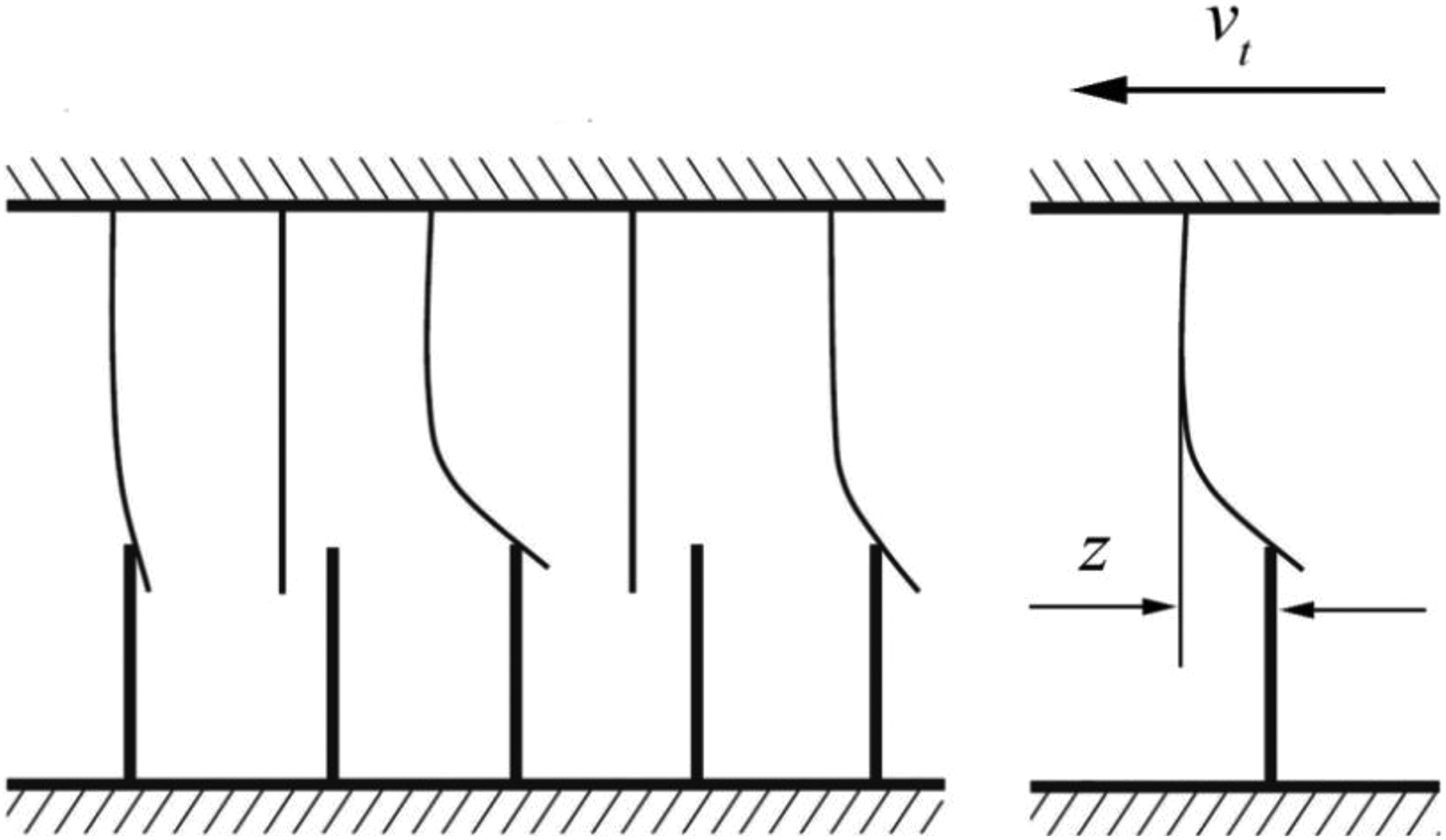
Physical interpretation of LuGre model.
The average deformation of bristle is expressed in z. Model is described as follows

where σ 0 is the bristle stiffness, σ 1 is the microscopic damping coefficient, and σ 2 is the viscous friction coefficient. The average deformation of bristle could be given by

where μk is the dynamic friction coefficient, μs is the static friction coefficient, and vs is the Stribeck velocity.
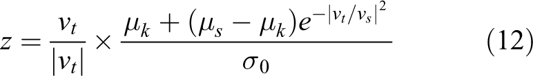
Besides, when the system reaches steady state, the average deformation z of bristle is constant, 30 so it can be given by

The contact force between socket and ball can be expressed as follows

According to reaction force and action force, contact force between socket and ball is as follows

Torque generated by contact force at the center of mass of bodies i and j is

where
Dynamic modeling of 4UPS-UPU spatial parallel mechanism with spherical joint clearances
Establishment of the coordinate system
4UPS-UPU spatial parallel mechanism diagram is shown in Figure 3. The parallel mechanism consists of a moving platform, a fixed platform, four identical UPS driving branches, and one UPU driving branch. Each driving branch consists of a swing rod and a telescopic rod. Fixed platform A is a fixed part, swing rods 6, 7, 8, 9, 10 and fixed platform A are connected via universal joint

Structure diagram of the 4UPS-UPU spatial parallel mechanism.
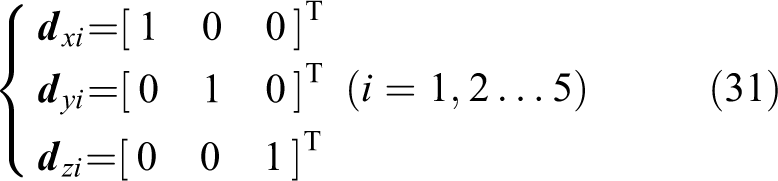
The global coordinate system
The lengths of telescopic rods 1, 2, 3, 4, 5 and swing rods 6, 7, 8, 9, 10 of 4UPS-UPU spatial parallel mechanism are expressed in
The motion of the moving platform of the mechanism is driven by changing the length of the five branches. And prismatic joint is used as the driving joint. The moving platform has five DOFs, which can move along XA , YA , and ZA axes in space and rotate around YA axis and ZA axis.
Conversion of coordinate system
The transformation matrix
Dynamic modeling of spatial parallel mechanism considering spherical joint clearances
The 4UPS-UPU mechanism contains 11 active components. The generalized coordinates of the mechanism are taken as follows

where
The schematic diagram of universal joint is shown in Figure 4. The universal joint connects body i and body j, where center point is P.


Diagram of universal joint.
where
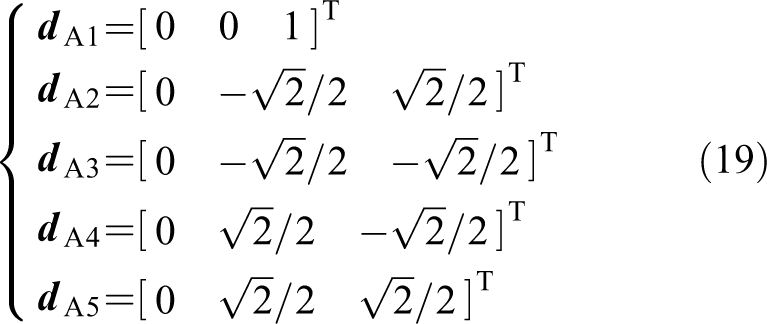
A schematic diagram of hinge point

Diagram of the fixed platform.
Position vectors of hinge point
The position vectors of hinge point
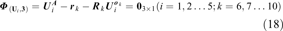
According to the first formula of equation (17), constraint equation of universal joint could be obtained as
As shown in Figure 5, unit vector
And the unit vector

According to second formula of equation (17), the constraint equation of universal joint could be obtained as

According to equations (18) and (21), the constraint equation of hinge joint

Similarly, the constraint equation of hinge joint

Figure 6 shows spherical joint constraints that connects two bodies i and j. The center of spherical joint represents point P.


Diagram of spherical joint.
where
For the 4UPS-UPU mechanism, coordinates of spherical joints
Respectively, coordinates of spherical joints
According to equation (24), the spherical joint constraint equation of 4UPS-UPU spatial parallel mechanism can be given as
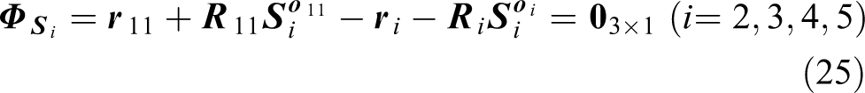
Figure 7 shows prismatic joint that connects body i and body j.

Diagram of prismatic joint.
According to the characteristics of the prismatic joint: (1) the connection

where
For the 4UPS-UPU mechanism, the distance from

The distance from

Then the direction vectors from point Q to point P can be expressed as

The

The
According to equation (26), the constraint equation of the prismatic joint of 4UPS-UPU spatial parallel mechanism is obtained as follows

The 4UPS-UPU spatial parallel mechanism has five DOFs, so it needs to impose five driving restrictions to enable the mechanism to have a definite motion. Through inverse kinematics analysis of spatial parallel mechanism, the relative distance curve from the centroid of swing rod to the centroid of telescopic rod, namely

By integrating equations (22), (23), (25), (32), and (33), the kinematic constraint equations of 4UPS-UPU spatial parallel mechanism in the idea case can be written as

Considering clearance presented in spherical joints (S
2 and S
5), the difference between the clearance spherical joint and the ideal spherical joint is that the constraint at the clearance spherical joint is replaced by force constraints. Therefore, corresponding constraint equations

Velocity constraint equations could be obtained by differentiating equation (35) with respect to the time, it can be written as

where
A second differentiation of equation (35) with respect to the time is acceleration constraint equations

where
The mass matrix of 4UPS-UPU spatial parallel mechanism can be expressed as

where
The dynamics equations of parallel mechanism can be given by

where
Equation (37) could be added into the equations of motion (equation (39)), the dynamic model of 4UPS-UPU spatial parallel mechanism including multiple spherical clearance joints can be written as

Equation (40) does not directly apply displacement constraint and velocity constraint equations, and it might violate the original constraint equations. At present, the more commonly used and effective method proposed by Baumgarte is Baumgarte stabilization method, which is to damp out acceleration constraint violations by feeding back violations of position and velocity constraints. 22,26,34 So, it can be given by

where
Dynamic simulation example
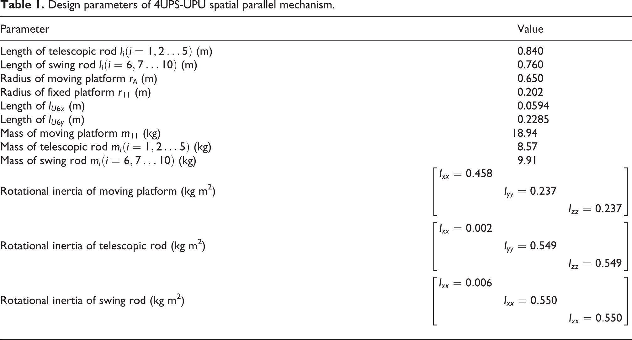
The 4UPS-UPU spatial parallel mechanism with two spherical joint clearances is taken as an example to verify the correctness of the model established above. The design parameters of 4UPS-UPU spatial parallel mechanism are listed in Table 1. And dynamic simulation parameters are listed in Table 2.
Design parameters of 4UPS-UPU spatial parallel mechanism.
Dynamic simulation parameters of 4UPS-UPU spatial parallel mechanism.

The two spherical joint clearances are both set 0.3 mm, and the trajectory of moving platform is set as follows (unit: s, m)
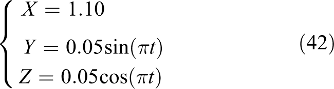
The dynamic response of the mechanism with two spherical joint clearances was obtained by programming with the help of MATLAB2018b software. At the same time, the model of 4UPS-UPU mechanism with two spherical joint clearances is also modeled in ADAMS. And the results of dynamic response obtained by ADAMS are compared with those obtained by MATLAB, as shown in Figures 8 and 9.
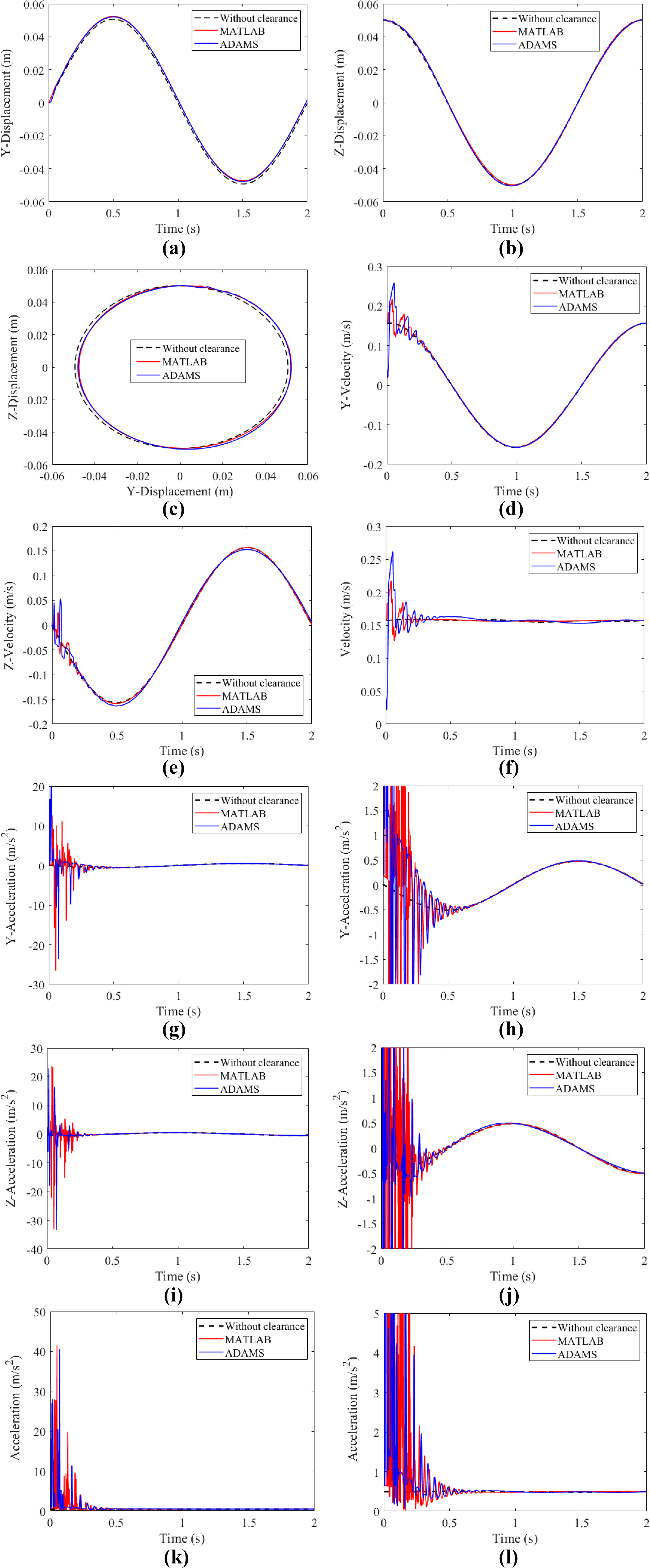
Dynamic responses of 4UPS-UPU spatial parallel mechanism: (a) Y-displacement, (b) Z-displacement, (c) total displacement, (d) Y-velocity, (e) Z-velocity, (f) total velocity, (g) Y-acceleration, (h) enlargement of (g), (i) Z-acceleration, (j) enlargement of (i), (k) total acceleration, and (l) enlargement of (k).

Dynamic responses of 4UPS-UPU spatial parallel mechanism: (a) contact force in joint S 2, (b) enlargement of (a), (c) contact force in joint S 5, (d) enlargement of (c), (e) the center trajectory diagram in joint S 2, and (f) the center trajectory diagram in joint S 5.
The displacement curves of the moving platform are shown in Figure 8(a) to (c). It can be seen that curves of MATLAB with two spherical joint clearances is coincided basically with those of ADAMS with two spherical joint clearances. The movement trend of ideal displacement curve and displacement curve with two spherical joint clearances is basically consistent and coincidence, which shows that the clearances have little effect on displacement of mechanism moving platform. The velocity and acceleration curves of moving platform are illustrated in Figure 8(d) to (l). In the initial stage of motion for mechanism, the velocity and acceleration of the center of mass of moving platform change greatly. The reason is that the contact force caused by clearance increases the collision between components, which makes velocity and acceleration of mechanism fluctuate greatly. The following velocity and acceleration curves with clearances are coincided with those without clearances. And the curve with clearance by MATLAB and the curve with clearance by ADAMS have the same overall movement trend, which shows the correctness of the established dynamic model to a certain extent. Figure 8(f) to (l) shows the total velocity and acceleration, since the total velocity and acceleration take into account the vibration in the X direction, the vibration in the X direction is random, so after 0.5 s, the ideal curve is slightly different from the curve with two spherical joint clearances.
Figure 9 shows contact force and center trajectory at spherical clearance joints (S 2 and S 5). From Figure 9(a) to (d), it can be seen that contact force changes abruptly at initial stage of motion, and subsequent contact force tends to be stable. According to Figure 9(a) to (d), the overall movement trend of MATLAB curve and ADAMS curve is basically the same. Because of difference of solving method and modeling between MATLAB and ADAMS, the simulation with clearance has randomness, which result in different initial collision positions, thus the peak time of collision force is different. When mechanism is stable, two curves basically coincide with each other, which verify correctness of established dynamic model again. From Figure 9(e) and (f), it is shown that the center of the socket and ball coincide at the beginning of the movement, and the socket and ball are in separated mode. When driving force is applied, the socket and ball have a violent impact, which cause fluctuations in speed, acceleration, and collision force. And then the socket and ball are in a continuous contact state, and the mechanism gradually enters a stable state.
Conclusions
In this article, a general modeling method for parallel mechanism with multi-spherical joint clearances based on Lagrange multiplier method is proposed. Taking 4UPS-UPU spatial parallel mechanism as an example, the dynamic model of the mechanism with two spherical joint clearances combining Flores contact force model and LuGre friction model is established. According to the built model, the dynamic response of the mechanism is obtained using MATLAB, including displacement, velocity, and acceleration of moving platform, the contact force, and the central trajectory diagram at spherical clearance joints. The ADAMS model of 4UPS-UPU spatial parallel mechanism with two spherical joint clearances is also established and simulated. Correctness of model has been verified through comparing results of MATLAB with those of ADAMS. It can be seen from this example that the dynamic model of spatial parallel mechanism with multi-spherical joint clearances can be easily established by this method, which provides a theoretical reference for other scholars to establish the dynamic model of parallel mechanism with multi-clearance in the future.
Footnotes
Declaration of conflicting interests
This manuscript has not been published, simultaneously submitted or already accepted for publication elsewhere. All authors have read and approved the manuscript. There is no conflict of interest related to individual authors’ commitments and any project support. All acknowledged persons have read and given permission to be named. Xiulong Chen has nothing to disclose.
Funding
The author(s) disclosed receipt of the following financial support for the research, authorship, and/or publication of this article: This research was supported by the Shandong key research and development public welfare program (grant no. 2019GGX104011), Natural Science Foundation of Shandong Province (grant no. ZR2017MEE066), the open project of Heavy-duty Intelligent Manufacturing Equipment Innovation Center of Hebei Province (grant no. 201904), and Postgraduate Science and Technology Innovation Project of Shandong University of Science and Technology (grant no. SDKDYC190221).