
Abstract
With the development of modern cities, the demand for cleaning glass curtain walls in urban skyscrapers is increasing, and therefore, many researches on facade cleaning robots have been carried out in the past few decades. In this article, a novel type of facade cleaning robot based on four-ducted fan is proposed. To improve the load capacity of the robot, the lifting and horizontal movement are, respectively, supported by an independent lifting mechanism and a lateral movement mechanism. Unlike the previous passive and active suction, the powerful suction power of the robot is provided by the four-ducted fan. Meanwhile, the obstacle-climbing force is caused by the forward of the four-ducted fan that improves the crossing obstacle ability. In addition, an incremental sliding mode algorithm is applied for controlling the posture when the robot crosses obstacles, which can ensure the stable performance of the cleaning robot under disturbance. Some simulations and experiments are conducted and the results demonstrate the effectiveness and robustness of the designed facade cleaning robot.
Keywords
Introduction
With an increasing number of glass curtain walls in urban skyscrapers, the demand for facade cleaning is also growing rapidly. However, cleaning glass curtain walls is a dangerous and time-consuming task for humans, and facade cleaning robots are then designed to replace humans to complete these works. The facade cleaning robot has great potential to be able to complete the wall-cleaning work independently with high efficiency, which has attracted many researchers to devote their energy to finding a reliable solution in this community.
The facade cleaning robot is a kind of special service robot. It contains key technologies with facade adsorption, designs of lifting device, and related control methods. Facade adsorption technologies for glass curtain walls include the passive sucker, 1 –3 the active sucker, 4,5 the thrust adsorption by using fans, 6 –9 and so on. Lifting technologies include rope driven, 6,8,9 leg types, 4 wheel types, 3,7 and sliding frame types. 1,2,5 The wall-climbing robots used to clean have been studied in recent decades, but there is no mass-produced commercial products for glass curtain wall cleaning, and the existing research work is mostly focused on structural designs. 1 –10
Many researchers are dedicated on the designing of wall-climbing robots for cleaning glass curtain wall, 1 –10 especially in some researches such as Nansai et al. 1 cleaning robot with self-reconfigurable mechanism and a biped mechanism, 4 the ingenious mechanical structure improves the flexibility of the robot, and it still causes some control problems. Tun et al. 2 have proposed a kind of robot that uses negative pressure sucker driven by self-locking guide screw to adsorb on the glass surface. The robot uses sliding frame to achieve self-climbing function; however, the sliding structure reduces the load capacity that makes it insufficient for glass facade cleaning efficiency. The Serbot 3 uses a cyclically rotating passive suction cup group to move on the wall and can overcome some low obstacles, but it can’t cross over when the obstacle is higher than the extension of the suction cup.
Some solutions involve the use of wires and ropes. 6 –10 Yoo et al. 10 have developed a robot for cleaning glass curtain walls which is equipped on a gondola improves the load capacity, and the robot manipulator is used to clean the facade, but it’s too heavy to be portable. Jin-gang et al. 8 have proposed a glass facade cleaning robot driven by two flexible ropes through imitating spiders pulling silk in the air to move. A single fan is used to provide negative pressure for adsorption. The stability of the fan is better than the sucker, because the latter may not be able to suck tightly. In addition, the length and width of tall buildings put forward requirements for the length and control of ropes, which are not suitable for practical applications. Some proposed solutions have designed the platform of the wall-climbing robot with rope ride. Seo et al.’s work 9 has adopted two propeller thrusters and a one-degree of freedom wall-cleaning unit using a ball–screw mechanism to perform a cleaning task, it is 20 kg, which is not conducive to transportation and portability. The method of using a ducted fan and a tilt-rotor mechanism has solved the problem of the soft landing of the wall-climbing drone in Myeong and Myung’s work, 6 and there are still potential safety hazards due to motor failure. The approach of using duct fans to provide adsorption force and rope as driving force has been proposed in Kim et al.’s work. 7 It adopts a portable rope ascender for efficient wall-climbing. In addition, the ducted fan’s ability to provide adsorption and lift has been validated in Andrikopoulos and Nikolakopoulos’s work. 11
Although these solutions have their own advantages, there are difficulties that are yet to be solved when it comes to the integration among the weight, load capacity, adsorption capacity, obstacle crossing ability, and cleaning efficiency. To mitigate these problems, a portable cleaning robot is proposed in this article. The robot adopts the design of rope lifting and horizontal movement of automated guided vehicle (AGV) to balance the gravity of the cleaning robot and remove the self-propelled mechanism that improves the load capacity. Meanwhile, four-ducted fans are applied to ensure the adsorption stability and improve the ability to cross over window frame obstacles. And the cleaning disc and suction pump installed on the cleaning robot guarantee the cleaning effect.
The control of the robot is closely influenced by its structure. The structure of the robot is inspired by the quadrotor unmanned aerial vehicle (UAV). To improve the stability of robots control, various approaches have been proposed: fuzzy proportion integration differentiation (PID) method, 12 neural network PID method, 13 reverse step method, 14 the sliding mode control (SMC) method, 15 and linear active disturbance rejection method. 16 Many researchers have developed various types of facade cleaning robot along with their control strategies. 17 –20 However, many of them who focus on the posture control of the robot are preliminary and need to be improved further. The SMC has been applied to various aspects of the robot and quadrotor in some researches. 21 –23,24 –26 The model described in Perozzi et al. 22 can be used to track trajectory, and thus the robustness of the quadrotor is improved. An integral sliding mode controller (ISMC) proposed in literature 23 improves the controller performance of the sliding mode controller. However, there are few researches about the control stability and robustness of curtain wall-cleaning robots, let alone with other special obstacle-crossing scenarios, which require a higher level of robustness and stability on the controller.
In this article, a novel portable facade cleaning robot based on four-ducted fan is proposed. Firstly, the robot adopts four-ducted fans to ensure the balance ability and reduce the weight, which is inspired from UAV. It also has the ability of flexibly flying cross the obstacles such as the window frames and this ability is not limited by the size of the wheels. Secondly, the rope lifting design can not only enhance the load capacity but also has the function as safety ropes. Thirdly, for instability in the process of crossing obstacles, the dynamic model of four-ducted fans is established and the incremental sliding mode controller is applied. The incremental sliding mode controller can make the system response rapidly and be insensitive to disturbances (especially anti-interference ability to the roll angle).
The rest of this article is organized as follows. In the second section, the structural design of the cleaning robot and the construction of dynamic model are discussed. The third section illustrates the design and shows the simulation of the controller and its stability toward posture when the robot is crossing obstacles. The experiments and data analysis carried out to prove the effectiveness of the proposed control method are given in the fourth section. The conclusions and future works are given in the fifth section.
Structural design and dynamic modeling
Structural design
The facade cleaning robot designed in this article aims at miniaturization, easy control, and high adaptability which requires the compact structure and high space utilization. Light materials can reduce energy consumption. In addition, the small size can be adapted to a variety of glass structures and can improve the control performance. The system schematic diagram of the facade cleaning robot system is shown in Figure 1(a) and the front view of the lifting mechanism is shown in Figure 1(b). The schematic diagram of the system structure is shown in Figure 2(a) and axonometric drawing of the 3D model is shown in Figure 2(b).

System of facade cleaning robot. (a) System schematic diagram and (b) front view of lifting mechanism.

Structure of the cleaning robot system. (a) Schematic diagram of system structure and (b) 3D model. MCU represents microcontrol unit. NVIDIA TX2 is a power-efficient embedded computing device.
The facade cleaning robot is composed of the body, lifting mechanism, and transverse moving mechanism. The horizontal moving mechanism is an AGV and the lifting mechanism is a hoisting machine installed on AGV whose specific structural components are shown in Figure 2(b). Four-ducted fans are distributed across the body, and each posture control of the cleaning robot is realized by combining the force of rope drive with the principle of quadrotor. The structural composition of the body is shown in Figure 3(a) and (b). Fans can provide a stable suction force to absorb and enough lift to cross obstacles. Ultrasonic sensor and camera are also installed on the body, which work together to measure the distance between robot and obstacles. The feedback of posture information can be obtained from the inertial measurement unit (IMU) attached to the robot. There are independent controllers in the three sets of mechanisms, and the main controller in the cleaning robot communicates wirelessly with other controllers and terminal devices. The two discs clean the glass surface in an artificial way. Meanwhile, the suction pump mounted on the cleaning robot is responsible for recycling dirt.

Structural composition of body. (a) Axonometric drawing of body and (b) end view of body.
The control framework of this robot is shown in Figure 4, and it is divided into three subsystems, namely admin control system, cleaning robot control system, and auxiliary control system. QT is used in admin control system to design the human–computer interaction interface, in which the relevant controller algorithm code is embedded. The camera in the image module directly transmits image information with TX2 through the USB interface. In cleaning robot control system, cleaning robot micro control unit (MCU) obtains the distance information and pose information corresponding to the flying obstacle by using ultrasonic sensor and IMU. For real-time data transmission and communication with the IMU, universal asynchronous receiver transmitter (UART) appeared as an excellent trade-off. During obtaining distance information, ultrasonic sensor is connected to communicate with cleaning robot MCU by IIC mode. The speed and steering of the ducted fan are controlled by cleaning robot MCU through the electronic speed controller (ESC). The cleaning motor in the cleaning module is driven by cleaning robot MCU output IO signal to the relay. The same driving principle is the lifting motor of the lifting module and the traversing motor of the traversing module. Additionally, the Zigbee is connected to the MCU on the body and the auxiliary control system, respectively, and communicates with the corresponding MCU through UART. The admin control system is at the level of remote control, which can be connected to the human–computer interaction interface through Wi-Fi module named ZigBee. As for the power supply, it is divided into two parts, one of which is a current regulator to power the cleaning robot, and the other is a Lithium-Polymer battery (LIPO) battery power supply to the AGV and the lifting mechanism in the auxiliary control system.

Control frame of cleaning robot.
Dynamic modeling
To begin with, the dynamic model of the cleaning mechanism is established. 23,27 The transformation relationship between the ontological coordinate system and the ground coordinate system of the cleaning mechanism is obtained, 25 as shown in Figure 5.
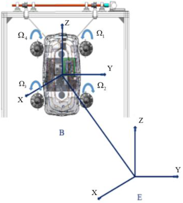
Coordinate system of cleaning robot.
Conversion matrix between ontological coordinate system and world ground system is as follows 26

where


where E and B refer to the ground coordinate system and the ontological coordinate system, respectively. x, y, and z represent the linear position of the robot in three directions in the ground coordinate system, respectively.


In equations (5) and (6), c and s mean cos() and sin().
By deducing Newton–Euler Equation, the equation of rigid body dynamics can be simplified and expressed by the following equation
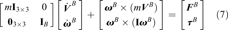
where
For the convenience of deduction, let

where
The dynamics equation is simplified to equation (9)


where

where

where
The facade cleaning robot is affected by a variety of forces and moments, such as gravity

(1) Force vector

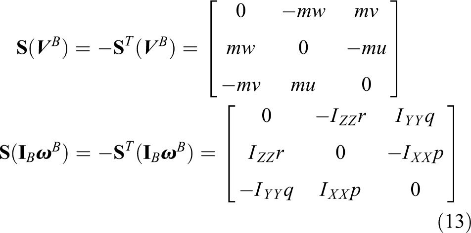
(2) Gyroscopic effect
(3) According to the hydrodynamics theory, the force and torque of the propeller are affected by four forces and torques in the flow field. 29 They are thrust T, reverse torque Q, drag D, and roll moment L in the direction of motion. The numerical values are directly proportional to the quadratic of the speed of the ducted fan.
The sum of thrust of the ducted fan is along the X-axis direction of the body coordinate system, and there are four counter-torque effects of ducted fan in the X-axis direction of the system. Torque effects around Y and Z-axes of the system depend on the thrust difference caused by the speed difference of the four-ducted fans.

where
Equation (9) is arranged as follows

where
The dynamic equation of the robot is obtained as below

The four-ducted fans are controlled by equation (19) expressed as

Obstacle-crossing attitude control of robots
In the working process of the cleaning robot, the most vulnerable state to environmental interference is the state of overflying obstacles. In this state, it is necessary to keep the cleaning plane of the cleaning robot paralleling to the glass wall to complete the cleaning work safely. In this process, the roll angle (around Z-axis) of the robot needs to be stably controlled so that it can be stabilized in a numerical range.
Because the SMC is independent toward the object parameters and disturbances, the SMC has the advantages of rapid response, being insensitive to the corresponding parameter changing and disturbances, no online identification of the system and simple physical realization. Therefore, it is suitable for the working environment of the facade cleaning robot. 30 And the SMC control system block diagram is shown in Figure 6.

SMC control system block diagram.
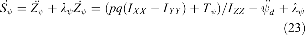
A sliding mode controller is designed to control roll angle around Z-axis. 31 Firstly, the dynamic equation of the angular acceleration around the Z-axis can be obtained from equation (18).

Then, the dynamic equation of the sliding mode controller is derived from equation (20)

where
A second-order system can be obtained from the dynamic equation (21) of the roll angle. Based on the empirical design, the sliding surface

where
Set

To satisfy the accessibility condition of slip form,
It can be obtained by using the equivalent control law

where k1 represents the constant in the equivalent control law, satisfying that k1 is greater than zero.

To prove that the roll angle of the controller can converge to the expected value in finite time, the Lyapunov function V is defined as

If its derivative value
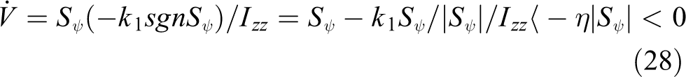
Therefore, under the control law, the Lyapunov stability condition is satisfied, and the roll angle will reach the sliding surface in a finite time.
In the actual realization of the control function, due to the unstable control quantity of the system is roll angle, to simplify the control, the fans on both sides are uniformly controlled. Firstly, the control variables are simplified and equivalent. To constantly maintain the cleaning plane of the cleaning robot always parallel to the facade, the thrust T1 and T4 generated by the two-ducted fans arranged on the upper side of the cleaning robot need to be greater than the thrust T2 and T3 generated by the two-ducted fans arranged on the lower side. The difference value is epsilon, which is a time-varying parameter to maintain the posture of the cleaning robot parallel to the wall. In the process of the robot moving vertically on the wall, this parameter will actually increase with the enlargement of the lifting height, but the overall range will change with the various lengths of the rope because the cleaning robot’s obstacle-crossing height is not very high. We consider that this value does not change obviously in the working range, so we give it as a constant
The relationship between the upper and lower thrust of the ducted fan is as follows

The kinematic equation is

Because the cleaning robot actually cannot rotate around the x-axis, the speed of rotation around the x-axis can be regarded as 0, so make p = 0. Take place into the model with it, we can get

Because the two sides of the ducted fan are controlled in pairs, the equivalent control difference is defined as
Therefore

The relationship between the left and right sides of the ducted fan and the upper and lower sides of the ducted fan is brought into the kinematic equation for simplification.

Then the input amount is

Control quantity is as follows

Thus, the expression of the control quantity is obtained. To check the validity of the proposed method and obtain the reasonable values of the system parameters k1 and
The system parameters of the sliding mode controller are k1 and
As we know, the first and most important step is to control the robot’s posture. Therefore, in the process of cleaning and crossing the obstacle, the control in this article mainly focuses the attitude of the robot. We can know the performance of controller by analyzing the change of the angle and the angular velocity. Control simulation of roll angle and roll angular velocity diagram are shown in Figures 7 and 8.
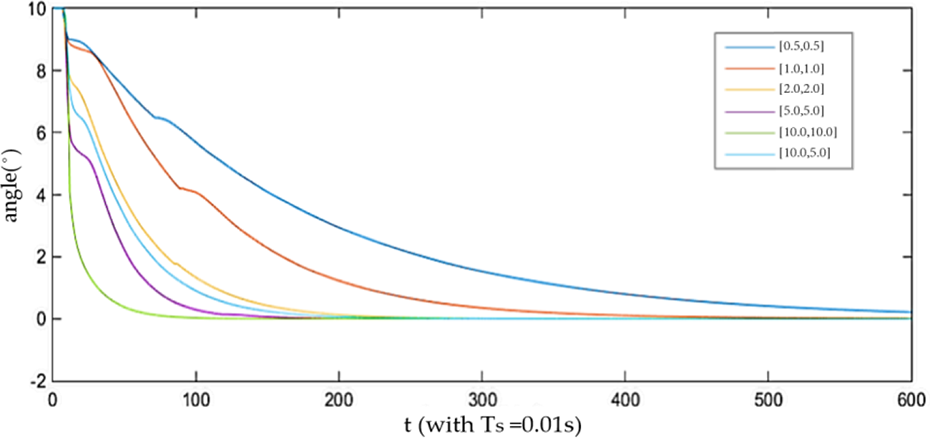
Simulation results of roll angle with different parameters.

Simulation results of roll angular velocity with different parameters.
The parameters of curves 1–6 corresponding to k1 and
It is clear from the curve that the fourth, fifth, and sixth curves have good control effect, which can make the roll angle return to the steady state in about 1 s. Through the simulation curve of roll angular velocity, it shows that although the fifth curve with k1 and
In this article, we only discuss the SMC algorithm aimed at stabilizing the roll angle. The classic PID control method based on desired position is designed for other two angles and the height from the robot to glass curtain wall, so that it can be stabilized near the angle of 0° and maintain a stable posture by the precise control of the most important quantities.
Experimental results
In this section, the experiment data of facade cleaning robot are analyzed, and the position and posture of the robot body are observed to verify the effectiveness of the motion control algorithm. We use the IMU to obtain the current posture information, ultrasonic sensors to measure the distance from the glass curtain wall, and camera to identify obstacles. Based on the data obtained by these sensors, the sliding mode controller is designed to process data and output the increment of thrust that needs to be adjusted. According to the offline calibration function between thrust and pulse width modulation (PWM) signal, the corresponding PWM signal value that needs to be adjusted is obtained. After receiving the signal, the ESC controls the attitude angle by adjusting the speed of the air duct so as to achieve a stable control effect.
The experimental conditions and physical parameters are given as follows. A glass plate and white foam are used to simulate the experimental environment. The size of the glass plate is 1600 mm × 600 mm (width × length) and the height of the window frame is 70 mm which is greater than those general heights. The size and weight of the robot are 400 mm × 200 mm × 250 mm (width × length × height) and 5.8 kg. The load capacity of the lifting mechanism is 25 kg. In the experiments, a large amount of data are collected and processed into images in two cases, one is when the cleaning robot reaches the obstacle-crossing height of 9 cm without interference, and the other is when the robot receives an instantaneous roll angle of 25° interference.
The posture stabilization control effect of the sliding mode controller is observed separately. The experiment platform is shown in Figure 9 and the variation of angle without the controller is shown in Figures 10 to 12.
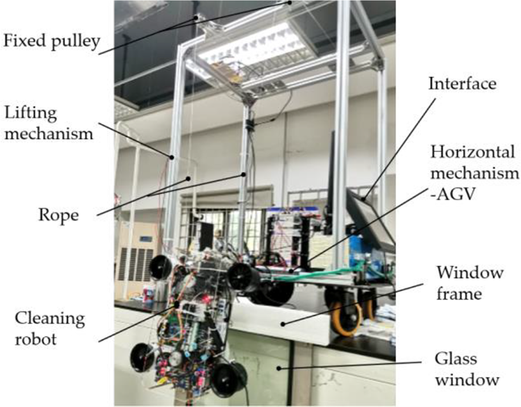
Experimental platform of cleaning robot.
The angle around Y-axis without the controller.

The angle around X-axis without the controller.

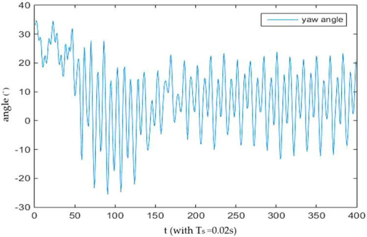
The angle around Z-axis without the controller.
It can be seen from Figures 10 to 12 that without the controller, the angle of the cleaning robot around each axis will gradually fluctuate greatly and irregularly, which, in other words, is in an unstable state. The variation of roll angle around Z-axis has reached nearly 70°, but the variation of other two Euler angles is significantly smaller than the former one which is around Z-axis. For this reason, the control of roll angle is the main problem of obstacle-crossing, and we have applied the SMC algorithm to solve this problem. The effect of this method without interference is shown in Figures 13 and 14.

Angular response curve around Z-axis without interference.
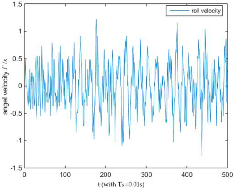
Angular velocity response curve around Z-axis.
From Figures 13 and 14, we can tell that the roll angle around Z-axis, which is the angle we mainly need to control, is maintained in the range of 4° and the angular velocity is maintained in the range of 1.5° per second after we use the sliding mode controller. It can be seen as a stable state when the facade cleaning robot flying up and over obstacles, which meets the design requirements of robots in overcoming obstacles. And the effect of this method with interference also performs well as shown in Figures 15 and 16.

Angular response curve around Z-axis with interference.

Angular velocity response curve around Z-axis with interference.
For the roll angle around Z-axis, a disturbance fluctuation of about 25° occurs, which quickly returns to about 0° within 3 s, and the maximum adjustment range of angular velocity reaches 10° per second.
The overall adjustment effect is ideal, the adjustment time is short, the anti-interference performance is certain, and the steady-state position effect is good. Such an index has fully met the working requirements. Regardless of interference, the cleaning robot will not touch the wall when it flies over the obstacle.
In the actual experiment, the height of the flying obstacle is set to be 9 cm. When the height of the flying obstacle is reached to 9 cm, the range deviation of the control maintenance effect is about 0.6 cm, and the effect is relatively ideal, as shown in Figure 17. Its crossing obstacle ability is up to 10 cm, which is better than the latest wall-cleaning robot. 1 –10

Response curve of flight height at maximum obstacle height.
When the robot is lifted to fly over the obstacle, the effect is shown in Figure 18(a), where the white foam bar is the simulated obstacle. The cleaning effect of common glass stains is also experimented in this article. To clearly show the cleaning effect, a piece of black glass is used as the cleaning target. Dust and water are the most common stain on the wall of glass curtain. In this experiment, moderate white dust was found on the black glass surface. The cleaning process is from bottom to top, using the designed artificial cleaning disc and vacuum pump to complete the cleaning, as shown in Figure 18(b).

Cleaning process and effect. (a) Process of crossing obstacle and (b) cleaning effect.
The cleaning method of facade cleaning robot adopts the “Z” route, which is from bottom to top and from left to right. After cleaning a whole piece of glass, it crosses the barrier to reach the next piece of glass through the wall. According to the actual cleaning experiment, the cleaning area needs to be partially repeated to ensure that all glass surfaces are traversed. Therefore, the actual cleaning efficiency will be slightly lower than the theory value. After testing, a 1 m2 glass surface needs to be moved horizontally about four times, then cleaned vertically, and the total time taken is about 1.5 min including the adjustment time of the position and posture of the robot.
Conclusions
In this article, a novel portable facade cleaning robot based on four-ducted fans is proposed. In terms of structure, our contribution is to greatly improve the load capacity and reduce the weight of the cleaning robot by designing an independent lifting mechanism and a horizontal mechanism on the AGV. In addition, the design of the four-ducted fan can not only provide the thrust required for negative pressure adsorption but also increase the height of the robot body through obstacles to a maximum of 15 cm. Furthermore, the overall design of the cleaning robot body is lightweight and miniaturized to easily adapt to various types of window frames.
In terms of the control of robots crossing obstacles, our contribution is to stabilize the posture so as not to hit obstacles though the design and application of incremental sliding mode controller. The dynamics model for the cleaning mechanism is presented based on the structure of the body. An incremental sliding mode controller is mainly designed for the roll angle around Z-axis when the robot crosses obstacles. The experimental results demonstrate the reliability and robustness of the sliding mode controller. The validity of the structure and controller of the facade cleaning robot is verified, and the cleaning effect of dust and water stain is effective. It achieves the design goals of miniaturization, easy control, and high adaptability.
In the future, we will consider enlarging the size of the structure to greatly improve the cleaning efficiency and optimizing the control algorithm. Meanwhile, better resistance to crosswinds is the focus of our next research work. In addition, we also think that thoroughly addressing some application-specific issues requires further research.
Footnotes
Author contributions
Formal analysis, review and editing, and validation of the article were performed by X-PL and XW; methodology and original draft preparation by X-PL and BF; and software by BF.
Declaration of conflicting interests
The author(s) declared no potential conflicts of interest with respect to the research, authorship, and/or publication of this article.
Funding
The author(s) disclosed receipt of the following financial support for the research, authorship, and/or publication of this article: This work was financially supported in part by the Shenzhen Science and Technology Innovation Commission.