
Abstract
Brain–computer interfaces (BCI) have been focused on improving people’s lifestyles with motor or communication disabilities. However, the utilization of this technology has found news applications, such as increasing human capacities. Nowadays, several researchers are working on probing human capabilities to control several robotic devices simultaneously. The design of BCI is an intricate work that needs a long time to its implementation. For this reason, an architecture to design and implement different types of BCIs is presented in this article. The architecture has a modular design capable of reading various electroencephalography (EEG) sensors and controlling several robotic devices similar to the plug-and-play paradigm. To test the proposed architecture, a BCI was able to manage a hexapod robot and a drone was implemented. Firstly, a mobile robotic platform was designed and implemented. The BCI is based on eye blinking, where a single blinking represents a robot command. The command orders the robot to initiate or stops their locomotion for the hexapod robot. For the drone, a blink represents the takeoff or landing order. The blinking signals are obtained from the prefrontal and frontal regions of the head by EEG sensors. The signals are then filtered using temporal filters, with cutoff frequencies based on delta, theta, alpha, and beta waves. The filtered signals were labeled and used to train a classifier based on the multilayer perceptron (MLP) model. To generate the robot command, the proposal BCI used two models of MLP to ensure the classifier prediction. So, when the two classifiers make the same prediction, within a defined time interval, send the signal to the robot to start or stop its movement. The obtained results show that it is possible to get high precision to control the hexapod robot with a precision of 91.7% and an average of 81.4%.
Introduction
Nowadays, technological development has played a significant role in our everyday lives, where comfortableness and improving the quality of life also play an essential role. There is a need for building machines for doing productive workload, making cumbersome or almost impossible processes easier for human beings, and at times, it has been substituting human handwork, in the case of industries. The development of moving robots has been an answer to this need. Mobile robots can be divided into autonomous and nonautonomous. The first ones are smart machines capable of doing tasks in their surroundings without humans’ explicit control. Such robots have to be able to develop themselves in entirely unknown environments. 1 On the other hand, the nonautonomous robots need to be operated, through a control interface, by a human to do the task. 2 These interfaces are denominated man–machine and allow communication among humans with different machines or robots. The man–machine interfaces can be of various types, such as graphics or remote controls, but both usually use a series of commands to define the activities to be carried out. 3 Currently, the computer systems need the model design of the interfaces adapted to the individual and social needs of the user. 4
During the last years, a significant development in the world of technology has been produced. One of the areas that have received more benefits from such development is the interface area. Currently, the interfaces are more sophisticated, reduced, and with more benefits. 5 Nevertheless, research in speaking-recognition technology or robotics, along with nanotechnology, opens new windows and paths to the future, allowing us to develop new applications and devices that will have an impact on our lives. 6
In this sense, the use of communication means has been proposed, where user intentions are interpreted through brain activity monitoring. These interfaces are denominated brain–computer interface (BCI). 6,7 Also, Lee et al. 8 define it as a communication technology between a person and a device without the need to interact physically. In other words, it takes the instructions directly of what the brain is ordering.
BCIs use different technologies to measure electrical activity. Some of these technologies are electrocorticography, intracortical electrodes, functional spectroscopy of closest infrared, picture through functional magnetic resonance, magnetoencephalography, and electroencephalography (EEG). 9 The BCI combined with the EEG can be used for different applications; the most common ones are for medical or industrial use. 2 Other forms are the control of devices, such as mouses and keyboards of a computer, monitoring the state of a driver, entertaining, and video games.
Some enterprises have published their devices to measure neural activities and the video games that are compatible with themselves. 9
However, BCI’s design is an intricate work that needs a long time and specialized devices for its implementation. Additionally, its design requires knowledge of electronics, programming, digital signal processing (DSP), and artificial intelligence (AI), to name a few. For this reason, an architecture to design and implement different types of BCIs was developed and presented in this article. The architecture is composed of several interchangeable and customizable modules capable of reading and controlling various kinds of EEG sensors, integrating different DSP and AI algorithms and managing different robotic devices. The architecture was validated with the implementation of a BCI able to control a hexapod robot and drone. A user will teleoperate the devices through the blinking signals. The project uses different classification methods, such as the support vector machines (SVMs) and artificial neural network (ANN), specifically the multilayer perceptron (MLP) model. The main goal is to test the architecture adaptability and reconfigurability to different BCI design.
The article is organized as follows: the state-of-the-art is presented in the second section. In the third section, the BCI architecture modules and their functionality are presented. The results and discussion are presented in the fourth and fifth sections, respectively. Finally, the conclusions and future work are presented in the last section.
State-of-the-art
The following section shows the state-of-the-art concerning the BCIs and its implementations. Within the revision, we focused on the work related to the BCIs to control different devices.
One of the most common applications in the medical area is to control an electric wheelchair, with commands for turning in a particular direction, moving forward, or stopping. The EEG signal was extracted with a MindSet device from NeuroSky, having a Bluetooth communication. EEG signals were taken without processing to control the electric chair and long EEG signals to find attention and medication signals. The authors used band-pass filters, fast Fourier transform (FFT), and intensity average to processing the EEG signals. With the operation, direction, and going forward modes (when it detects an eye blink), a compass in the screen starts to rotate to select the course to advance. 10
Generally, the BCI systems have a preprocessing step. It is responsible for noise removal of the input signals; this step is critical in developing BCI systems. For that, several authors are proposed in different decomposition methods. For example, Sadiq et al. 11 propose an automated multivariate empirical wavelet transform (MEWT) algorithm for decoding different motor imagery (MI) tasks. This study’s main contributions are the principal multiscale component analysis method. A novel automated channel selection strategy is proposed. A sub-band alignment method utilizing MEWT is adopted, and a robust correlation-based feature selection strategy is applied to reduce the system complexity and computational load. The authors report experimental results of classification with an accuracy (Acc) average of 98% by employing MLP neural networks, logistic model tree, and least-square SVM classifiers. Finally, the authors concluded the great potential of the proposed MEWT algorithm for practical MI EEG signal classification.
Cho et al. present a study for decoding five different hand executions and imageries from EEG signals to control a robot’s hand. 12 In the experiments, five healthy subjects executed and imagined five sustained hand motions. In this motor execution (ME) and MI experiment, the authors proposed a subject-specific time interval selection method, and we used common spatial patterns and the regularized linear-discriminant analysis for the data analysis. As a result, the authors reported the classified five different hand motions offline and obtained an average classification Acc of 56.83% for ME and 51.01% for MI.
A brain connectivity analysis with EEG to propose a brain functional network (BFN) and use a feature extraction algorithm for decoding a subject’s voluntary hand movement is presented by Li et al. 13 By analyzing the characteristic parameters obtained from the BFN, the authors extracted the critical electrode nodes and frequencies for identifying the direction of a hand’s movement. The results demonstrated that the most sensitive EEG components were for frequencies delta, theta, and gamma1 from electrodes F4, F8, C3, Cz, C4, CP4, T3, and T4. Finally, they proposed a model for decoding the right hand’s voluntary movement using a hierarchical linear model (HLM). Through a voluntary hand movement experiment in a spiral trajectory, Poisson coefficient between the measurement trajectory and the decoding trajectory was used as a test standard to compare the HLM with the traditional multiple linear regression model. The authors found that the decoding model based on the HLM obtained superior results equal to 87.2%.
Another BCI system is proposed to control a virtual keyboard designed in LabVIEW. They focus their work on patients with amyotrophic lateral sclerosis, who have muscular weakness and atrophy all over their bodies, losing control of almost all their bodies, except for the muscles responsible for the movement in their eyes. So, the work uses the eye blinking to control the keyboard. The authors characterized the peaks of muscular tension with some sort of variability in the amplitude. They used the FP1, F3, FP2, and F4 electrodes, which are in the frontal and prefrontal regions. To detect the blinks, they use the kurtosis coefficient or central momentum of the fourth order, that is, significantly high when there are closed eyes, open eyes, or blinks, while other signals, such as the subject’s movement, have a small value of the coefficient. With this method, the speed of one-character selection per minute is obtained because, in the first 20 s, the keyboard block is selected, in the next 20 s, the column is selected, and in the last seconds, the character is selected. 14
The EEG signals for blinking can be classified by any classification method like SVMs or ANNs. The BCI application based on an eye blink is presented by Sarma et al. 15 They focus on differentiating the voluntary blinks of spontaneous blinking so that the users do not have to keep their eyes open until they need to send a control signal. They used an Emotiv EPOC device of 14 electrodes and 2 references, applying digital slot filters of 50 and 60 Hz. Furthermore, an IIR Butterworth filter was applied at 0.16 Hz to eliminate the feeding line’s noise. Evident blinking effects were found in the electrodes AF3 and AF4, the reason for deciding on only taking from the AF3 signal. The authors used an SVM classifier, which is based on hyperplanes to differentiate two or more classes. The classes were open eyes, spontaneous blinking, and voluntary blinking. As the research objective, classifying these events was looked for with the SVM using different parameters. According to their results, the best kernel was the cubical one for the three events classification, while the linear kernel was for the spontaneous blinking and voluntary blinking. Another way of using the SVMs is proposed by Nguyen et al. 16 A speller was developed with a BCI using the EEG signals with the eyes closed, double blinking. This proposed system was designed to improve the BCI applications that require few commands, as it only uses the closing of the eyes to select and double blinking to undo the action, plus an open eyes event was added. The EEG signals with closed eyes were acquired in the occipital regions (O1 and O2), while for the double blinking, the frontal zone (FP1 and Fz) was used. The EEG signal was sampled at 500 Hz with a passing band filter between 0.1 and 40 Hz. The designed speller is made up of three layers, with three sections that have several letters, when one is selected, it expands this section until getting to the selection of the letter. For classifying a nonlinear SVM, radial base function was used. A linear classifier’s problem is that they have three classes, and the reason they opted for using three linear SVMs is having one classifier per class. With this proposed method, an average precision of 92.3% was obtained, sending control commands in an average of 1.8 s and completing a 10-letter word in an average of 2 min.
A popular classifying method is the ANN in their different variations. Sepúlveda et al. present a work focused on the classification of eye blinking signals and muscular pain, proposing two models of ANNs (RNA): MLP and an adaptive neuro-fuzzy inference system (ANFIS). This work was inspired in the timely detection of pain in disabled people, and that can no longer express pain, combining it with the EEG signals for eye blinking that provide an additional way of communication. The signals’ acquisition is made with an Emotiv EPOC system of 14 channels, processing the signals outside the line with the MATLAB software (9.6.0.1072779 (R2019a) 64-bits) and the EEGLAB tool. For the classification of the data, two experiments were done for the MLP and the ANFIS. The architecture used in the MLP was of five layers [120, 20, 10, 5, 1] and different types of adaptation algorithms to compare their results. In the ANFIS model, membership functions of the generalized bell or GBell were used. Comparing the results, the MLP with the adaptation algorithm of resistant retropropagation shows better results and a better classification of false positives shows the performance and robustness of this model of RNA.
Last, this article focuses on the detection of eye blinking using kurtosis and signal amplitude analysis, classifying them with an RNA and comparing it with different models. In the same way, they mention that the signals related to the activities from the eyes focus on the frontal and prefrontal regions, using the FP1 and F3 electrodes. For capturing, an RMS EEG 32 Super Spect system was used, having a negative peak that means an open eyes event and a positive peak when the eyes are closed and using the kurtosis coefficient, which is very high an event happens. At the same time, the other meaningless signals have a low coefficient. As it was mentioned before, different RNA models were tested, specifically feed-forward backpropagation (FFBP) and cascade-forward backpropagation (CFBP). Their results showed a better performance in CFBP than in FFBP. 17
Brain–computer interface architecture
In the area of AI, a BCI is a technology that approaches us more to interacting with electronic devices. We will have direct communication with them and will be able to understand what we think and do actions that we will order to it. It has a significant amount of applications from which outstand the medical and control applications, and in the future, it could be a new way of communication. Nevertheless, it is not such a researched topic, the reason for which this article presents a new tool to either develop or improve the existing BCI and increase this research field that is still growing. In Figure 1, a diagram of the BCI architecture is presented. It is composed of three custom and reconfigurable modules that can be programmed in different languages and executed in one or various computers. In the next subsections, the description functionality of each module is presented.

Architecture diagram for the development of BCI using robotic devices. It is composed of several custom and reconfigurable modules. BCI: brain–computer interface.
Electroencephalography devices
For the design of the BCI, it requires a specialized equipment for obtaining the EEG signals. In the market, there exist different models and brands that adapt to the research requirements. In this project, two different models were used. The first one is the Epoc+ equipment from the brand EMOTIV. 18 The Epoc+ is a portable device with high resolution (14 bits); it has 14 channels (electrodes) and 2 references. The channels have a sampling capacity of 128 Hz. The distribution of the sensors is based on the International system 10–20. 19 Based on the electrodes’ individual readings, Epoc+ is possible to develop BCI capable of detecting and processing thoughts, emotions, and expressions in real time.
The second one is the Aura device from the brand Mirai Innovation, Minamihonmachi, Chuo -ku, Osaka, Japan. 20 The Aura has eight channels and allows the acquisition of biosignals, such as EEG signals (brain), electromyogram signals (muscle), electroculogram signals (eye), and electrocardiogram (heart). The channels have a sampling capacity of 250 Hz. The device can communicate by wired connection (via USB 2.0) and Bluetooth 2.1 (range up to 30 m.). Also, the distribution of the sensors is based on the International system 10–20.
Figure 2 shows the Epoc+ and Aura devices and Figure 3 shows the distribution of the sensors based on the International standard 10–20, where the letters indicate the area (AF, prefrontal; F, frontal; FC, central; P, parietal; T, temporal; and O, occipital) and the numbers designate the hemisphere (evens from the right and odds from the left). 21

(a) Epoc+ EEG and (b) Aura EEG device used for the design and test of the BCI architecture. BCI: brain–computer interface.

Location of the sensors based on the International standard 10–20.
Digital signal processing module
The DSP module is the input of the architecture and has the tasks of interconnecting with the EEG devices and filtering the brain signals.
EEG signal acquisition process
The architecture was tested by the development of the BCI to control two robots using different EEG devices and algorithms. The control is done through the AF channel signals. These channels are in charge of measuring the neural activity of the prefrontal lobe. Such lobe coordinated a diversity of activities, such as the resolution of problems, creative thinking, judgment, intellect, attention, behavior, physical reactions, abstract thought, coordinated movements, coordinated muscles, and personality. 22 Specifically, the sensors AF3 and AF4 were used. These sensors can give enough information to detect blinking activity. 23 –25 The data recorded by the EEG device were extracted with the CyKIT v2 software and AURA.
Biosensing kit
Both applications provided an interface with which it is possible to confirm when the command event happens. Here, the blink of the subjects was the command to control the robots. To interconnect the EEG devices to the BCI architecture, the lab streaming layer (LSL) is used. The LSL is a system for the unified collection of measurement time series in research experiments that handle both the networking, time synchronization, real-time access, as well as optionally the centralized collection, viewing, and disk recording of the data. 26 The LSL protocol allows communication with all the modules in the BCI architecture.
The data used in this project were obtained with the collaboration of 15 healthy subjects (10 males and 5 females, aged from 20 years to 31 years) without any experience in BCI use. The data obtained with only those of 10 subjects were used since the rest not selected presented problems in the acquisition process. They were informed about the protocol to follow in the experiment and the objectives of the project. Also, they signed an informed consent document in accordance with the official Mexican Standard NOM-012-SSA3-2012. When putting the EEG device on, they were indicated to take their time for relaxing to avoid that the signals that come from other mental processes cause noise in the signals of the AF3 and AF4 sensors. When the subjects were ready, they were asked to blink when they were ordered to; such orders would happen every 5 s.
EEG signal processing
The DSP task was done using different specialized libraries and implementing some filters designed by us. The software OpenViBE 2.2.0 released for synchronizing the signal with the controller of the robot was utilized. OpenViBE offers a wide variety of tools for stimuli, filters, storage, visualization, and synchronization of the signal. The raw signal that comes straight from the EEG device can be used to extract signals that indicate a blinking, but they may contain noise. So, the signals were processed with notch and Hamming window filters.
The notch filters are also known as band-stop filters or band-reject filters. They are a highly selective form of the band-stop filter, which can be used to reject a single or very small band of frequencies rather than a whole bandwidth of different frequencies. 27 For example, it may be necessary to reject or attenuate a specific frequency generating electrical noise, which has been induced into a circuit from inductive loads, such as motors or ballast lighting, or the removal of harmonics, and so on. 28,29 Band-stop filter can be represented as a combination of low-pass and high-pass filters if the bandwidth is wide enough that the two filters do not interact too much. For standard notch filter, equation (1) is written as follows

where ω 0 is the central rejected frequency and ωc is the width of the rejected band.
Figure 4 shows the notch filter response in domain frequency. Here, the values of f 1 and f 2 are the cut frequency values. In the presented architecture, the notch filter eliminates the noise from the sensors’ energy line (60 Hz). So, the values of cut frequencies f 1 and f 2 to eliminate the 60 Hz noise are 59 and 61 Hz, respectively.

Notch filter response in domain frequency. The notch filter is used to eliminate the noise from the sensors’ energy line (60 Hz).
A window filter is a function used to smoothly bring a sampled signal down to zero at the sampled region’s edges. Its design is fast, convenient, and robust, but generally suboptimal. It is easily understood in terms of the convolution theorem for Fourier transforms. 27 The Hamming window is an extension of the Hann window. 30 Its parameters permit the optimization of the destructive sidelobe cancellation. In particular, when α is adjusted to 25/46 (0.543478261), the first sidelobe is canceled (see Adams 31 and Bojkovic et al. 32 ). The common approximation to this value of α is 0.54, for which the window is called the Hamming window (equation (2)). The time response of this filter is shown in Figure 5. In this work, the Hamming window filter is used to soften the signals from EEG sensors and was implemented using a window size of 256 samples


Time responses of Hamming window filter used to soften the signal from EEG sensors. EEG: electroencephalography.
As is observed in Figure 6, two plots are presented, where they show the comparison between the signals without any filter on the top plots and the signals with notch filter and window filter on the bottom plots. The plots show that the signals with the application of filters achieve to highlight the peak of the blinking event. Moreover, the size of the sample was reduced. The sampling frequencies pass from 256 Hz to 64 Hz.

(a) In the graph in the plot, the EEG signals are observed without any filter. (b) In the graph in the plot, the notch and Hamming window filters were applied. Here, the application of filters achieve to highlight the peak of the blinking event. EEG: electroencephalography.
The problem of notch and window filters is that they do not provide enough representative characteristics of a blinking event’s corresponding signal. For this reason, additional filters were applied to the signals that are used for the robot controllers. The captured raw signals had a temporal filter applied to them, using the band-pass filter, which is in charge of producing the plainest signal attaching to the cut frequency. The transfer function of a band-pass filter is given by equation (3)

where ω 0 here is the frequency at which the gain of the filter peaks Q has a particular meaning for the band-pass response. It is the selectivity of the filter and is defined by equation (4)

where f 1 and f 2 are the frequencies, where the response is –3 dB from the maximum. The band-pass filter response is shown in Figure 7. The band-pass filter helps to eliminate the noise made by external elements or sensor movements.

Spectral responses of band-pass filter used to eliminate the noise made by external elements or sensor movements.
Different pairs of frequency cut values were approved, which correspond to the values of the delta, theta, alpha, and beta cerebral waves.
The comparison among the band-pass filter values shows that the signal with a low cut frequency of 0.1 Hz and a high cut frequency of 3.9 Hz was capable of eliminating most of the noise without affecting the shape of the blinking event (Figure 8).

Signals processed using temporal filtering in different frequency cutoff values, corresponding to brain waves (a) delta, (b) theta, (c) alpha, and (d) beta. Band-pass filter values show that the signal with a low cut frequency of 0.1 Hz and a high cut frequency of 3.9 Hz was capable of eliminating most of the noise without affecting the shape of the blinking event.
Classification module
The proposed aim is directed toward the application of BCI capable of controlling different robotic devices. The classification process can be done using ANNs, nearest neighbor, SVMs, decision trees, boosted trees, and so on. Here, we do not want to propose a novel classification method. Instead, we want to show the architecture versatility to use any model without modifying the previous modules. So, we used ANN based on MLP model. The ANN is an adaptive parallel system with exciting features, such as organizing, adapting, learning, fault-tolerant, and organizing data by rapid processing of complex and nonlinear multidimensional and temporally varying information. 33 They can deal with real-time processing problems that have persistently evaded solution by alternative methodologies. 34 Over the last few years, the ANNs also have increasingly been used to classify biosignals, such as heart disease problems. 35 –37
An MLP is a feed-forward ANN model that can be used to map input data sets into a set of appropriate outputs. MLP passes input to output through one or more connected hidden layers. Several parameters affect the results, such as the number of hidden layers, weights, and activation functions. 38
For the MLP implementation, each EEG signal is divided into windows of 50 samples and represented the network’s input vector. In the architecture, two identical MLP nets were implemented over Python language using ThensorFlow tool. 39 The MLP architecture consists of five layers, an input layer with a dimension of 50 neurons, a three hidden layer with a dimension of 100, 150, and 100 neurons, respectively, and an output layer of one neuron. We applied a sigmoid function (equation (5)) in the hidden and output layers. The resume parameters of the MLP net are presented in Table 1. Every created net corresponds to the AF3 and AF4 sensors. They are trained with the labeled signals, such as blinking, which have a length of 60 seasons. Furthermore, random samples of the same length were added, representing the signals that are not blinking. As shown in Figure 9, the AF3 and AF4 signals are sent into their corresponding MLP nets to be trained. To train the MLP, the vectors were labeled with 1, if there is a blinking signal in the window, and with 0, if there is no blinking signal in the window. Finally, the AND gate enters when the two classifier models agree with the prediction

Parameters used in the multilayer perceptron classifiers.

ReLU: rectified linear unit.
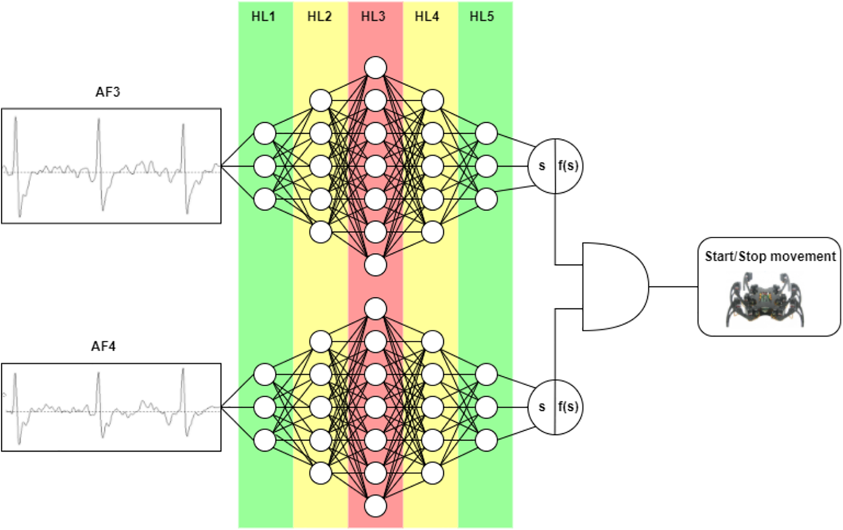
The architecture used for the multilayer perceptron design is composed of an input layer of 60 neurons, followed by five hidden layers of [50, 100, 150, 100, 50] neurons, ending with the output layer of one neuron, which defines if it is 1 = blinking or 0 = no blinking. The AND function enters when the two classifier models agree with the prediction.
Robot platforms
Finally, the robot platforms close the loop of the BCI architecture. Here, the BCI architecture was interconnected with a robot simulator and two different real robots. The objective is to show the architecture versatility and configurability to be connected with varying platforms of robots. Next, the robot platforms used in the BCI are described.
Hexapod legged robot: Mobile robots are a mechanic platform provided with a locomotion system capable of navigating through a determined working environment, supplied with a certain level of autonomy for its movement carrying loads. 40 For this, the robots depend a great deal on their mechanism of locomotion. Traditionally, the locomotion mechanisms are based on wheels as they make it easy for the control design. However, these mechanisms present a few disadvantages because they depend on the terrain conditions to obtain proper performance. For this reason, in recent years, it has been seen the need to develop locomotion mechanisms based on articulations, such as the ones present in animals—these structures of locomotion display a variety of advantages standing out the adaptability to irregular terrains. 41,42
The proposed architecture can control different robotic devices, so a legged robot is used as a test device. The robot is a hexapod, Phoenix model, from the Lynxmotion, a RobotShop Inc. company, Mirabel, Quebec, Canada. 43 It has six articulated feet with three servos, adding up a total of 18 servomotors. Every servomotor represents a muscular action similar to those seen in insects (hip, femur, and tibia). The motors are controlled through a driver card. Figure 10 shows the complete hexapod robot of the Lynxmotion Company.
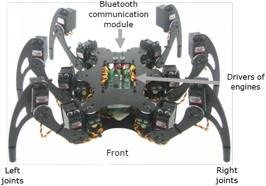
Complete hexapod robot of the Lynxmotion Company used to test the BCI architecture. BCI: brain–computer interface.
For the locomotion control, it is necessary to synchronize the six joints of the robot correctly. The control design is based on bioinspired principles. That is to say, a control diagram similar to the one seen in animals denominated central pattern generator. 44
The locomotion of hexapod robots is one of the most popular ones due to the ability to generate an inherent walking in a stable state. The type of walking in stable, mostly used in these robots, is known as a tripod. In the tripod gait, the external joints on one side and the joint in the middle on the opposite side are moving together just as shown in Figure 11. The figure shows how the joints labeled as R1-L2-R3 make up a group that moves synchronously. On the other hand, the joints L1-R2-L3 make up the other group that moves in unison. The locomotion in tripod produces a desynchronization between the two groups of 180° and is only necessary to generate two control signals. The tripod gait is a periodic movement, so it is possible to generate this gait using a periodic signal like sinusoidal waves. Figure 12 shows the relationship between the walking stages and the cyclic control signal.
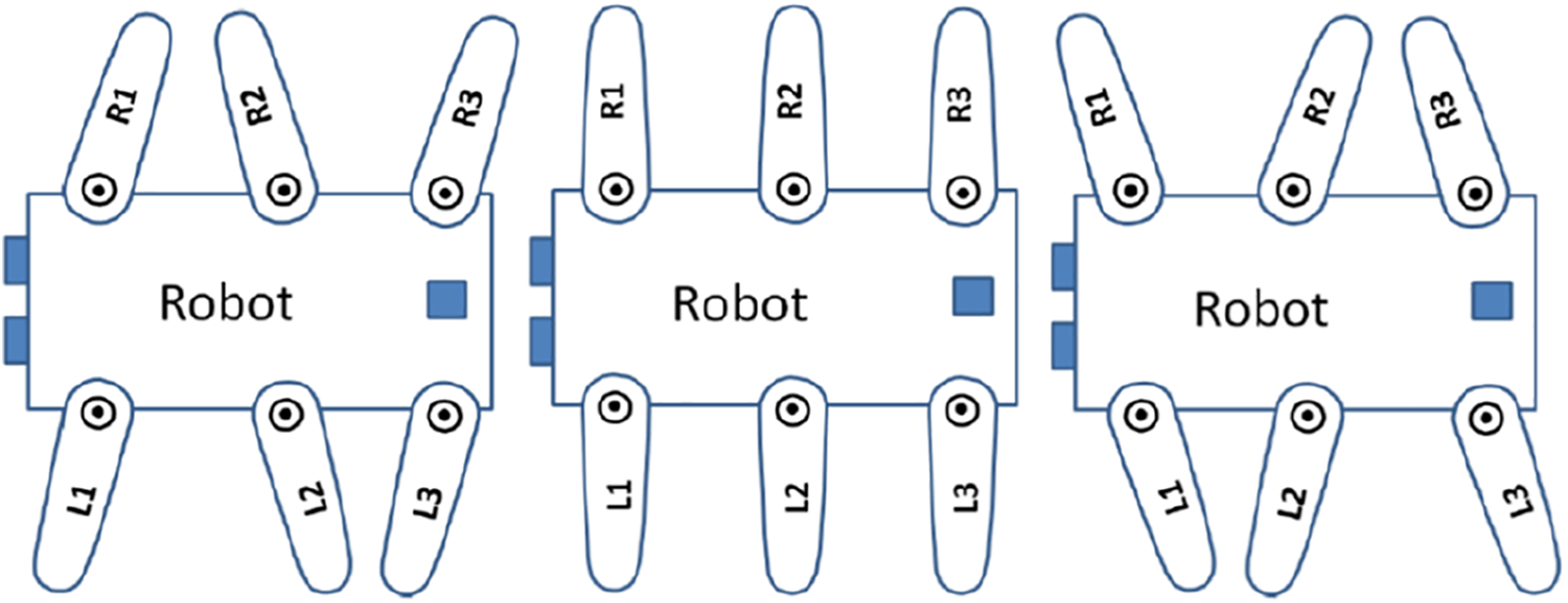
Gait known as a tripod. The outer joints on one side (R1-R3) and the joint in the middle of the opposite side (L2) move together while joints L1, R2, and L3 move at the same time.

Relationship between the walking stages and the periodic control signal.
The signals for the control of the join stare generated starting from equations (1) and (2), where A 1 and A 2 are the amplitudes of the sinusoidal waves, f is the frequency, and φ is the desynchronization of the X 2 periodic signal concerning the X 1 signal


The equations described previously are modeled to work in continuous time. Nonetheless, these are implemented through digital processor reasons for which it is necessary to discretize the signals. To carry out the discretization process, the continuous signals X 1 and X 2 are sampled in T time intervals and a finite number of n. As a result, equations (8) and (9) are obtained


where A 1 and A 2 control the amplitude of the signals in which the variable f modifies the frequency of the sinusoidal wave. These variables allow us to control the direction of the robot and the walking speed. Figure 13 shows an example of the graphics obtained for the control of walking. In the waves, it is considered the amplitude of 1 and a frequency of 2 Hz with a total of 64 samples.

Graph of the values that are sent to the servomotors to make a movement.
For the control and synchronization of the servomotors of the hexapod robot, the SSC-32 card is used. The SSC-32 card uses a protocol for sending commands to the motors, which are sent through the RS-232 interface. The communication protocol is made up of a character sequence that indicates the desired motor, speed, and direction of the motors. 45
The algorithm to control the robot movements is presented in Algorithm 1. Here, the hexapod robot initially is in a stop position. When a blink is detected, a true value is sending through Fbp variable, and the robot starts the forward movement (Fblink is true). Next, the hexapod robot stops the gait when a new blinking is detected (Fblink is false). This process is repeated until the communication with the robot is closed. The algorithm is used in the robot simulator and in the real hexapod robot.
Finally, the command communication between the control computer and the robot is done using a point-to-point protocol. For the reception of the command by the robot, a Bluetooth Zigbee module was used. This module performs as a serial port RS-232 that is transparently recognized as a COM port and can be used traditionally. All the robot controllers were programmed in python language.
Parrot Bipop 2 drone: Drones have been around for many years; they are used for different purposes and can be very helpful in many areas. However, drones have become much more popular in recent times, and their application has increased rapidly in various fields. Therefore, the areas of applications are numerous today, and there is a growing use of drones worldwide. The technology continues to advance, and it is a safe bet that drone usage will continue to grow as well. 46
The algorithm used to control the forward and stop movements of a hexapod robot using the eye blinking.


The Parrot Bebop 2, see Figure 14, is a smartphone-controlled drone with a 14 MP camera that offers 1080 pixels for video recording. The successor to the original Parrot Bebop model features a fisheye lens that allows for surprisingly judder-free footage and even boasts user-serviceable rotors. The USP of the Bebop 2 is the optional FPV pack, which includes a headset and professional-style flight controller, complete with sticks and buttons. Using this setup, it is possible to get a first-person view of what the drone is seeing, which is a surprisingly immersive experience. 47
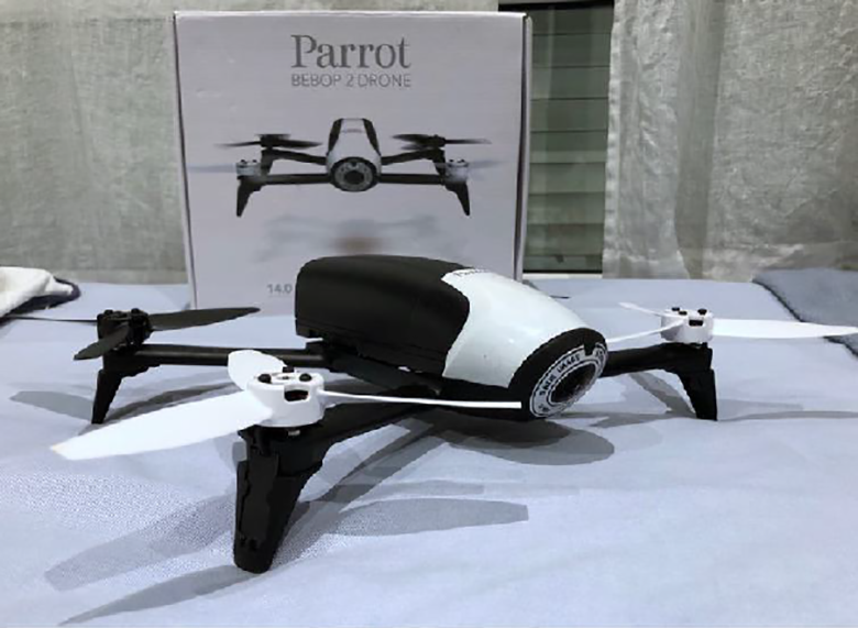
Parrot Bipop 2 drone used to test the BCI architecture. BCI: brain–computer interface.
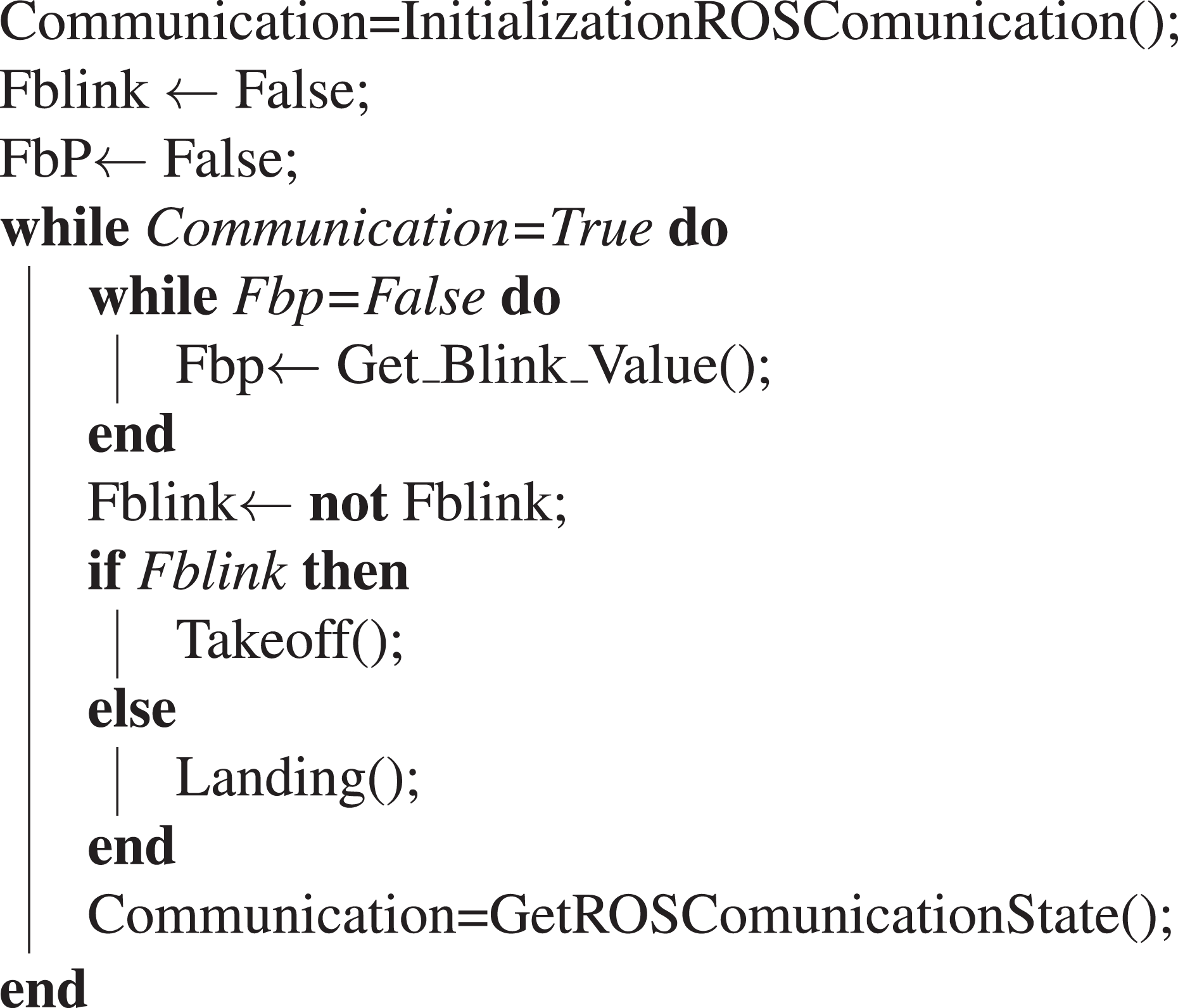
Parrot Bibop 2 is manipulated using the robot operating system (ROS) framework. Their philosophy is to make a piece of software that could work in other robots by making little changes in the code. What we get with this idea is to create functionalities that can be shared and used in other robots without much effort so that we do not reinvent the wheel. 48 ROS creates a network, where all the processes are connected. Any node in the system can access this network, interact with other nodes, see the information that they are sending, and transmit data to the network. Figure 15 shows the ROS architecture, where the ROS master provides naming and registration services to the rest of the nodes in the ROS system. It tracks publishers and subscribers to topics and services. The role of the master is to enable individual ROS nodes to locate one another. Once these nodes have found each other, they communicate with each other peer-to-peer. 49 Unlike the hexapod robot, the ROS framework helps us control the drone directly without programming the driver at a low level. The algorithm to control the takeoff and landing process is presented in Algorithm 2. Firstly, the drone is an initial position on the ground. When a blink is detected, it starts the takeoff. Then, the drone lands when a new blinking is detected. This process is repeated until the communication with the drone in ROS is closed.

Basic ROS architecture. ROS: robot operating system.
The algorithm used to control the takeoff and landing of a drone using the eye blinking.

Experimental results
Description of the experiment
Several tests were achieved to verify the functionality and versatility of BCI architecture to control different robotic devices. The test was done using robotic simulators and real robots were described in the last section. The test objective was to control the start and stop the robot’s movement using the eyes blinking.
For the experiments, the following specifications were taken into account:
In the first experiment, a v-rep robot simulation software was used. The experiment was used to control a hexapod robot and test the BCI architecture with a simulator software. Before starting the experiment, the classifiers have to be trained with the EEG signals previously captured. Then, the EEG signals were tested online, asking the subjects to blink when they were signaled in an interval from 5 s to 10 s of difference in every blink, reflecting those blinks in the simulator’s hexapod.
For the second experiment, the same procedure was done. The difference is that the testing scenario uses a real hexapod robot, which was designed and implemented in this work. The robot was placed on the floor, waiting for the signal, so it starts moving. Similarly, the subjects were indicated in an interval from 5 s to 10 s per blink. These two experiments used the Epoc+ devices to read the EEG signals.
Finally, in the last experiment, a real drone was used. Here, the takeoff and the landing were controlled, and the same instructions were followed. In this experiment, the EEG signals were obtained through the Aura devices.
Results of the experiment
The results of the proposed tests are shown in this section. Here, it compares the Acc, the rate of true positives (TPR), and the rate of false positives (FPR). These metrics were calculated offline during the classification test. As to say before, the sensors AF3 and AF4 reflect the blink event. Then, their signal was combined with a temporal filter to obtain a wave with a distinctive shape. The tests show results of classification, having an average Acc of 0.7903 in AF3 and 0.7808 in AF4, and an average TPR of 0.899 and 0.8701 in AF3 and AF4, respectively. Moreover, the tests allowed the calculated metrics of efficiency of the BCI, taking into consideration the true positives, false positives, and the false negatives. Then, the metrics of positive predict value (PPV) and TPR. The results are found in Table 2, in which it can be observed that the AF4 sensor shows better results in terms of prediction in blinking.
Results obtained in the offline classification for multilayer perceptron nets.

Acc: accuracy; TPR: true-positive rate; FPR: false-positive rate.
On the other hand, the online results did not vary with the obtained offline previously. This behavior is interesting because, in the online test, there is no control of wave position in the windows; the blink event can be in the beginning, center, or end of the window. The performance was estimated by counting the correct and incorrect predictions. In the no-blink class, the counting did no estimates because by having a continuous signal, the time windows change every season, so the total for no-blinking classes would be superior to the number of blink classes. That is the reason to choose to use PPV as metrics. In Table 3, the obtained results are shown. The combined classification of the AF3 and AF4 signals has a PPV average of 0.814.
Results obtained in the online classification for PPV and TPR metrics.

TPR: true-positive rate; MLP: multilayer perceptron; PPV: positive predict value.
The tests that were carried out to control a hexapod robot in real and virtual environments are shown in Figure 16. Here, the EEG signals of AF3 and AF4 reflect the blinking event with the corresponding order to move the hexapod robot in both experiments. (The complete videos of the hexapod robot experiments are available in https://youtu.be/uGqXnPv4ogw and https://youtu.be/2Ljt8T6d1cA.). In both tests, there was no problem with classifying and sending the order to the hexapod robot. The unique challenge is a slight delay in which the real robot starts or stops the movement compared to the virtual hexapod robot.
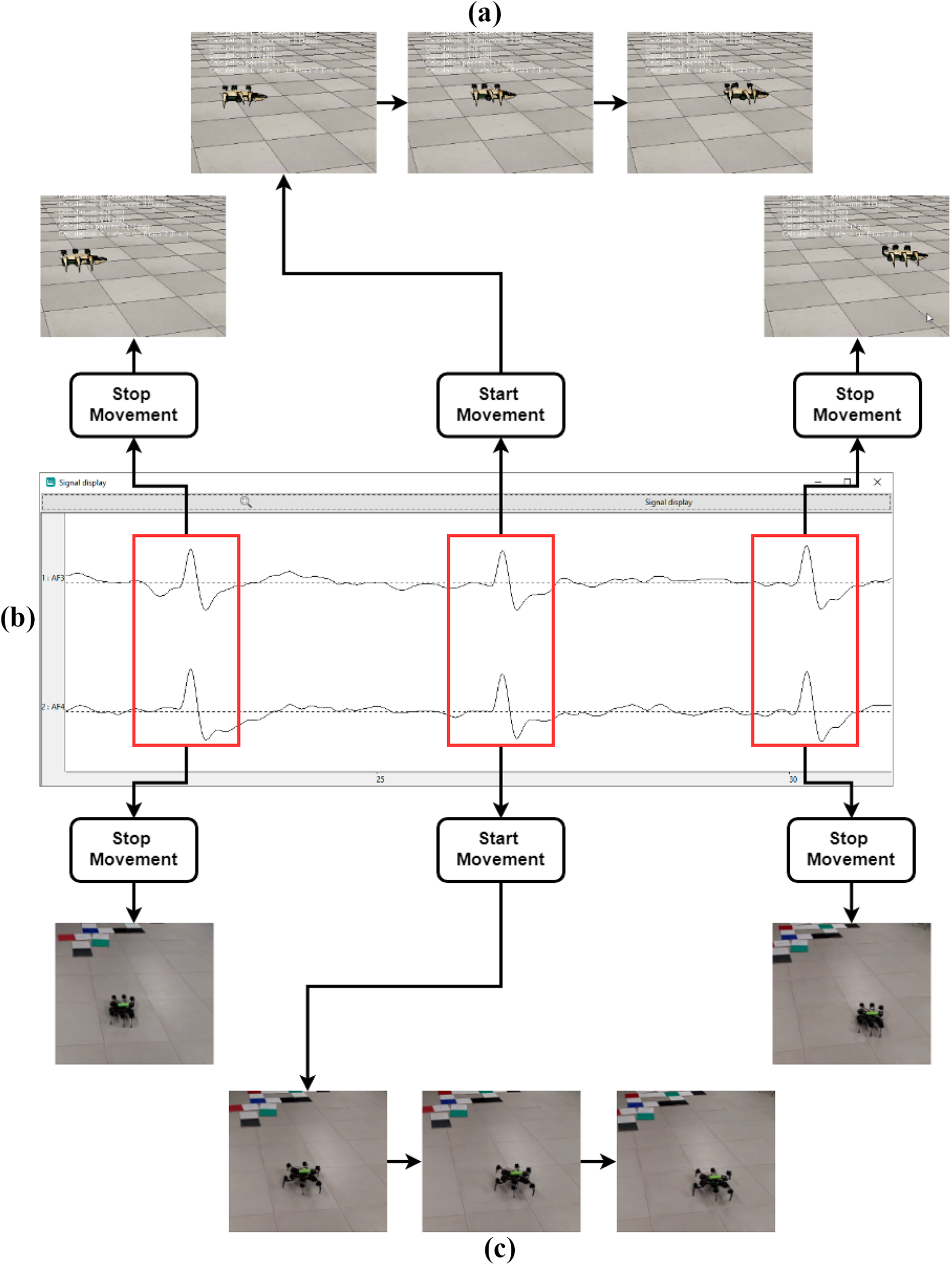
(a) Example of how the hexapod robot is controlled with blinking signals in the time domain. Here, each red rectangle contains the signal indicating a blink. (b) The initial position of the hexapod robot. (c) When a blink is detected, and if the hexapod robot is stopped, it starts moving forward. (d) The final position of the robot when stopped by the blinking.
The final experiment consisted of testing the versatility of the BCI architecture to be used with different platforms. In this case, the takeoff and landing process of a drone was controlled using the blink signal. For the experiments, the acquisition process module was modified to work with the Aura sensor. Also, the BCI architecture was connected to Parrot Bibop 2 through the ROS. The classification modules were not modified, and the same configuration parameters presented before were used. Figure 17 shows screenshots of the drone control experiment. (The complete video of the drone experiment is available in https://youtu.be/7I6jkJzii5g.)
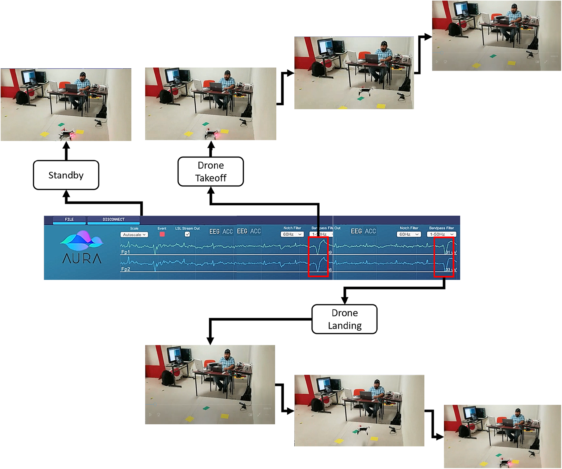
Example of how the drone is controlled with blinking signals in the time domain. Each blinking signal is detected and classified to control the takeoff and landing process of a drone.
Discussion
Table 4 presents a comparison of the proposed BCI architecture against some BCIs reported in the literature. For each work, there are different features, such as prepossessing and classification methods, number of electrodes, Acc, and reconfigurability, to name a few. The table shows that the proposed architecture presents competitive Acc using two channels and traditional classifiers based on neural networks and band-pass filters. It also shows that it is possible to utilize a generic versatile BCI architecture to control several robot devices. Compared with the reported BCI architectures in the literature, the proposed architecture is not fixed. It can be configured to select different EEG devices to read the brain activity (Epoc or Aura) and robotic devices (from robot simulator to a real hexapod robot and from hexapod robot to a drone) without modifying the rest of the BCI modules. Additionally, the modules can be adjusted remotely to either improve their performance or add new commands. The architecture can also be trained to classify other EEG signals without manipulating the rest of the BCI architecture. These architectures have not been well developed yet and have high possibilities of applications in diverse areas. Their main advantage is the reduction in time to implement a complete BCI. Currently, we are working on the addition of more characteristics to the BCI architecture. Some future characteristics are tools to extract the EEG signal features and add more robot communication drivers for simulators and real robots.
Comparison of the proposed BCI architecture against the works reported in the literature.

MLP: multilayer perceptron; EEG: electroencephalography; SVM: support vector machine; FFT: fast Fourier transform; LS-SVM: least-square support vector machine; CSP: common spatial pattern; RLDA: regularized linear-discriminant analysis; ANFIS: adaptive neuro-fuzzy inference system.
Concerning the experiment results, the main problem and a common one in the BCI are good quality EEG signals. As seen in Table 3, with the results obtained in subjects 5, 8, and 9, it was possible to get a good blinking precision thanks to low noise interference. On the other hand, the signals from subjects 5 and 6 showed a high level of noise. Although the same band-pass and noise elimination filters were applied, good blink characteristics were not obtained, resulting in a higher number of false blinking and lower classifier precision.
Conclusion and future work
In this article, a hardware–software architecture for developing and testing of BCIs is presented. The architecture is modular and easily configured to read to control different EGG sensors and robotic devices. The proposed architecture functionality was tested by designing and implementing a BCI to control robots using eye blinking. The BCI results show that it is possible to get high precision to control the robots with an Acc of 91.7% and 81.4%. Finally, the architecture showed its reconfigurability capabilities by controlling various kinds of robots using two different EEG sensors.
In future work, it is expected to implement more complex BCI to validate the architecture reconfigurability. Currently, we are working on several improvements in the area of processing methods and signal filtering. The idea is to lower the noise generated by the subject or external/internal factors. Finally, the next step will be to focus this work on the application in other devices, adding new commands to the blinking or combining it with other mental processes.
Footnotes
Declaration of conflicting interests
The author(s) declared no potential conflicts of interest with respect to the research, authorship, and/or publication of this article.
Funding
The author(s) disclosed receipt of the following financial support for the research, authorship, and/or publication of this article: This work was partially supported by PRODEP Project 511-6/17-7382 “Diseño e Implementación de Una Plataforma HW-SW para el Control de Locomoción en Tiempo Real de un Robot con Articulaciones Usando Principios Biológicos” and the CONACYT Project FC2016-1961 “Neurociencia Computacional: de la teoría al desarrollo de sistemas neuromórficos.”
Supplemental material
Supplemental material for this article is available online.
References
Supplementary Material
Please find the following supplemental material available below.
For Open Access articles published under a Creative Commons License, all supplemental material carries the same license as the article it is associated with.
For non-Open Access articles published, all supplemental material carries a non-exclusive license, and permission requests for re-use of supplemental material or any part of supplemental material shall be sent directly to the copyright owner as specified in the copyright notice associated with the article.