
Abstract
To improve the order fulfillment throughput and space utilization in the robotic mobile fulfillment system (RMFS), the research developed two design aspects: the layout design and the warehouse structural parameter configuration. Based on the semiopen queue network theory, we built the queue network model to estimate the performance of RMFS. A scheme was proposed to move the picking stations inside the storage area, and seven layout scenes were designed according to the location arrangement of stations and storage area. The performance estimation and parameter configuration platform were developed to support the experiments on layout optimization and parameter configuration. The result shows that the station’s internal layout improves throughput when compared with the external scheme and increases space utilization without storage zones. Vertical zoning increases performance significantly. The performance is sensitive to the zoning strategy and storage area structural parameters.
Introduction
With the rapid development of the e-commerce industry, the generation of small-batch, tiny frequency, small species, and higher timeliness massive orders has brought enormous challenges to business enterprises’ internal logistics. Nowadays, order picking becomes a bottleneck, restricting the development of medium-sized commercial enterprises. The method to achieve accurate and efficient order picking and rapid response is directly related to the core of major commercial enterprise development. 1
In recent years, automated picking solutions combining automatic equipment to realize the initiative of goods-to-people have emerged endlessly, such as autonomous vehicle storage and retrieval system, an intensive storage system, and robotic mobile fulfillment system (RMFS). 2 Since the first RMFS example was launched by Kiva system in 2012, it has been successfully promoted to major e-commerce order fulfillment centers around the world, including Amazon, Walgreens, and Staples in the United States, Jingdong, and Ali Cainiao.
Due to the high cost of introducing automated robots, detailed system design and planning in the early stages is the key to ensure the successful operation of the solution. Rational planning layout and structural parameter configuration are important strategic decisions at the strategic level. 3 Many design factors affect system performance and operating costs, such as the number of robots and workstations, the allocation of workstations, storage area size, and aisle density. At present, system planning and design in the field of practice mostly use simulation methods. The construction of simulation models takes a certain amount of time, and most of them are not universal and extensible. Therefore, designing a universal platform that can be used in the construction of the RMFS performance evaluation model and parameter configuration has important theoretical and practical significance for the decision makers in designing the system structure.
Although RMFS is very popular in practice, there are few related academic articles. The focus of such literature can be categorized into three categories, that is, system analysis, operational decision control, and system design optimization. 4 The literature that study the topic of system analysis are all using the queueing network model to estimate the performance of RMFS. Nigam et al. create a closed queue model for an RMFS. They estimate the throughput time for single-line orders based on a turnover class-based storage strategy. 5 Boysen et al. developed a closed-loop queuing network model to evaluate the performance of single-order line without zoning RMFS. They proved that the fixed robot task assignment strategy is more efficient in the order picking operation than the centralized robot task assignment strategy. It is the opposite of the replenishment operation. 6 Lamballais et al. establish a performance evaluation model based on semiopen queue network (SOQN) both for single-line orders and multiple line orders of RMFS and introduce approximate mean value analysis (AMVA) to solve the model to evaluate the performance of RMFS. The results show that the maximum order throughput is insensitive to the width-to-length ratios unless the ratio becomes strongly unbalanced. Furthermore, they indicate that the performance is sensitive to the position of picking stations under their settings. 7 Because the SOQN considers the external queue together with the system’s internal limited resource queue, therefore, it is closer to the actual production of the system. Thus, using SOQN models to analyze RMSF becomes mainstream since this article. Based on the assumption that the system throughput was determined, Yuan et al. established a single-service-station queuing model to simulate RMFS and took the order priority into account. 8 Zou et al. optimize the shape of the system using a SOQN model. 9
Many more articles study operational decision planning and control. Boysen et al. study the sequencing picking orders at the picking stations of RMFS. They formulate the problem as a mixed-integer program. The results indicate that the order throughput can be done with half of the fleet size of the vehicles using optimally sequencing order rather than the first-come first-served (FCFS) rule. The article also indicates that the number of robots reduces further using the shared storage policy. 6 Yuan et al. propose a velocity storage policy, where the popular items are located closer around the workstations. Compared with the random storage policy, this policy can reduce the travel distance of robots by 8% or 10%. 8 Lamballais et al. develop a SOQN model to estimate the order throughput time of the system. They study the ratio of the number of picking stations to replenishment stations and the replenishment level of each rack to reduce the total order throughput time. Their result shows that the optimal ratio of picking stations to replenishment stations is 2 to 1.
Furthermore, the optimal replenishment level is almost 50%. 10 Zou et al. studied the optimization strategy of RMFS to allocate robot to picking stations by establishing a SOQN model and propose a task allocation method based on the moving speed. They then design a proximity search algorithm to find the optimal task allocation rule. The results indicate that the random allocation strategy has advantages over the allocation method based on the moving speed. 11 Zou et al. studied the robot’s power management in the RMFS, and the results show that noncontact inductive charging is the best robot power recovery strategy. 12 Xu et al. study the standby strategy of the robot based on the shortest pickup time, and the results show that the strategy of standby at the end of the task is the best under the same layout. 13 Pan develops an advanced market algorithm to allocate orders to robots and design a simulation model to verify the method. 14 Qiu studies the vehicle scheduling and path planning and achieves the collision-free shortest path planning for robots using a modified A* algorithm. 15
We first describe the operation process and introduce seven layout designs for RMFS in the first section. According to whether considering the zoning strategy or not, two queueing network models are developed based on SOQN to estimate the performance of the system in the second section. The performance evaluation experiment platform designed to compare the maximum order throughput of the system under different structural parameters is introduced in the third section. Then, two experiments are designed to study how the structural factors affect the performance of the system. We conclude in the fourth section.
System description and design
Description
RMFS is mainly composed of automatic handling robots, mobile rack units, and picking operation platforms. The hallmark of the RMFS is the use of knapsack handling robots to move the storage unit from the storage location to the picking station.
Figure 1 shows the operating flow of the system. Firstly, the model takes the movement of the robot and the mobile rack unit as the research object. The movement processes are represented by M1, M2, and M3. When the picker in the operation platform completes the order picking task, the robot returns the picked rack units from the picking station to the designated storage location, and parks at the storage location, where the task ends and waits for the next task assignment. This moving process is identified as the M1 process. Secondly, picking orders enter the system in turn and are paired with an idle robot in the system. The robot bounds to the order travel from the current standby position to the storage location, where the mobile rack unit to be loaded is located at idle speed. This movement process is identified as M2. Because the robot can pass through the bottom of the mobile rack unit under no-load conditions, the walking distance belongs to the Manhattan distance. When the robot reaches the storage position of the mobile rack unit to be loaded, it stops and lifts the rack unit, and travels to the designated operating platform at the loading speed. This process is the opposite process to M1, and it is marked as M3.
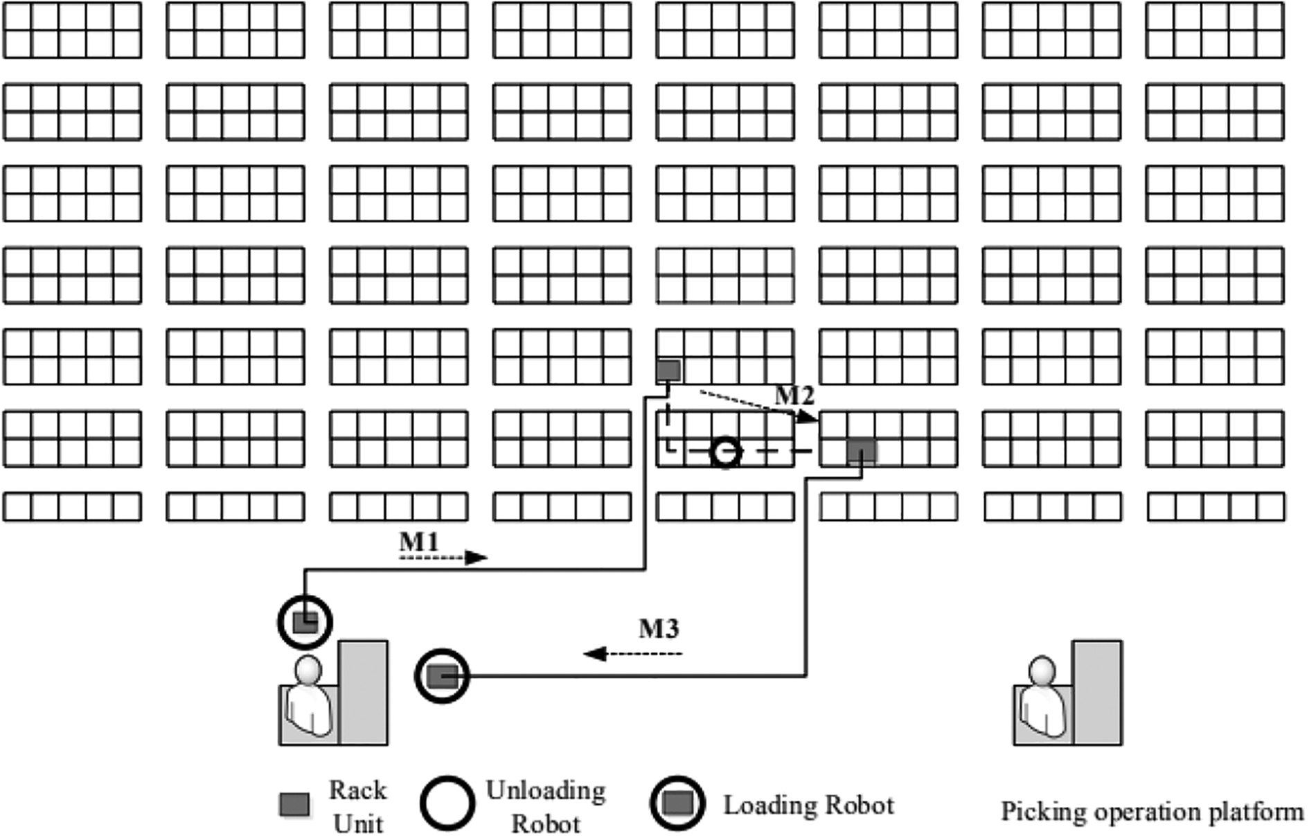
Schematic diagram of RMFS with the general operation process. RMFS: robotic mobile fulfillment system.
Layout design
The layout design of the storage area is an essential factor affecting the performance of the RMFS picking system, and it is one of the critical strategic decisions in the planning and design phase of the system. According to the picking stations distributed outside or inside the shelf storage area, they are classified into external and internal platform layouts.
External platform layout
The traditional RMFS storage area mostly adopts an external platform layout. The picking platforms are distributed around the storage area. The robot transports the storage area shelves to the platform for the picker to pick out the goods.
According to the number and position of the picking platforms placed on each side of the storage area, the representative layout of the platform’s external layout is listed in the following figure.
According to Figure 2(a), all picking stations are distributed on one side of the storage area. The layout of the functional area of the layout is relatively simple, and the subsequent processes, such as collection, packaging, and delivery, are relatively centralized and easy to manage. Figure 2(b) to (e) indicates the layout of the picking stations on multiple sides of the storage area in turn. The more centralized the picking station is, the easier it is to manage, and the walking distance of the robot increases appropriately.

(a–e) Schematic diagram of the external platform RMFS layout. RMFS: robotic mobile fulfillment system.
Internal platform layout
The automatic robot in the RMFS replaces the manual finding and handling of goods and realizes the process of the goods moving to people actively. Therefore, reducing the moving distance of the robot through the storage area layout design can greatly improve the system vehicle utilization rate, reduce the order processing time, and improve the overall system efficiency. To minimize the walking distance of the robot, a layout plan is proposed in which the operating platform is placed inside the storage area, and the picked order is sent out of the storage area through hoists and elevated conveyor lines.
According to the relative position of the picking platform in the storage area, the internal platform layout is divided into two types. One is a centralized internal platform layout, and the other is a distributed internal platform layout. The two layout plans are shown in Figures 3a and 3b.
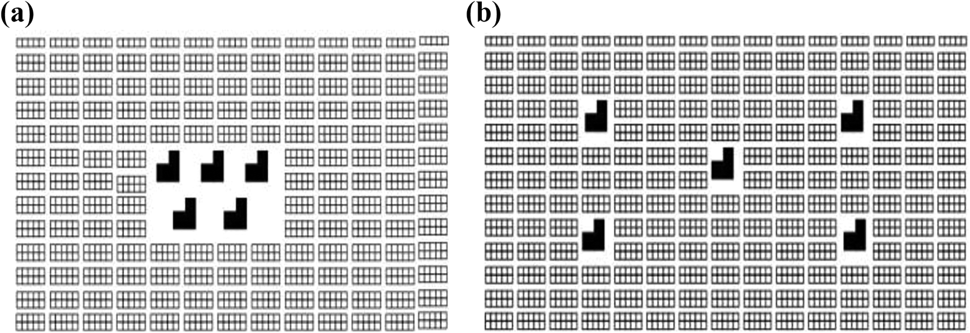
(a, b) Schematic diagram of the internal platform RMFS layout. RMFS: robotic mobile fulfillment system.
Assumption
The following assumptions are made in this study to realize the effective analysis:
Robot travels at a constant speed, regardless of acceleration and deceleration as well as the charging or maintenance time. The robot carries one rack at a time.
The commands in RMFS include retrieval tasks and storage tasks and only concern the retrieval task in this article. Besides, it assumes that the storage area always contains a rack with sufficient items of goods to satisfy each incoming order.
The arrival time interval of orders follows an exponential distribution. This assumption is the precondition rule to use SOQN to estimate the performance of RMFS.
The service of the robot for paths follows the principle of FCFS.
The picking time of the picking station follows a general distribution.
The retrieval task always occurs at a random policy. It means if the storage area is classified into zones, the location is random in each area. If not, it follows an arbitrary rule in the entire area.
The robot follows the principle of point-of-service-completion. That is, the robot chooses the completion point as its standby station and does not have to go to a predetermined dwell point after one cycle.
Aisles and cross-aisles have single directional travel everywhere. Delays at the aisle and cross-aisle intersections do not occur. This assumption is to avoid congestion and blocking during traveling.
Each location is square, and the edge length is one unit, and the width of each aisle and cross-aisle is equal to one unit too.
The distance between two adjacent stations on one side is the same.
Table 1 and Figure 4 presents the main symbols and meaning of each symbol in this article.
Main symbols and meaning of each symbol.

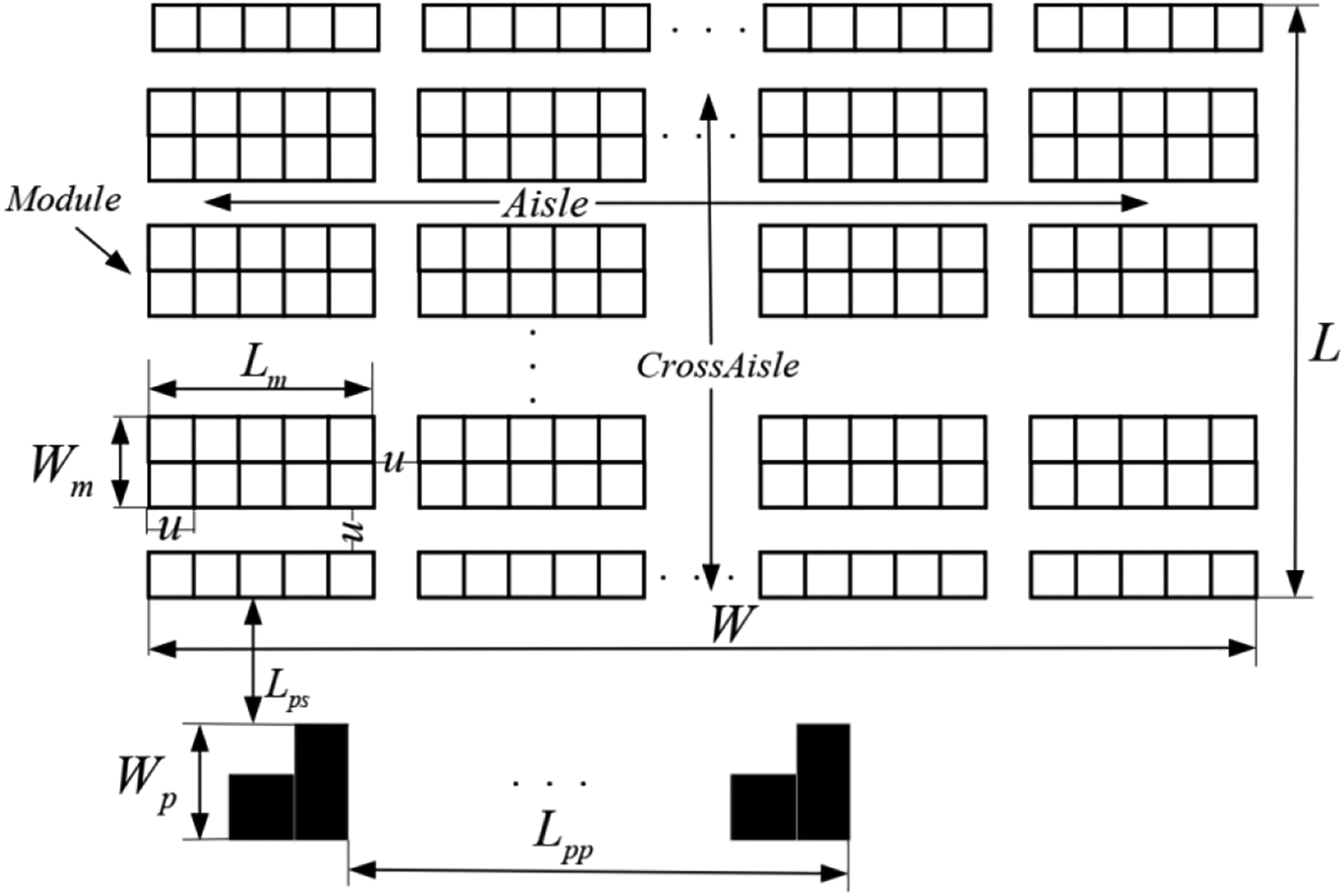
Overview of the structural parameters in the layout.
Modeling
Performance estimation model without storage zones
The RMFS process is described as follows: The system has an external task queue and an internal robot queue. The task enters the system from the outside at a certain hourly arrival rate. After the task is matched with the robot as a secondary resource, the robot moves from the standby position to the operation platform in the loaded state. The mobile rack unit is returned to the specified position after the unloading operation is completed. The process is constructed using a half-open loop queuing network model, as shown in Figure 5.

SOQN model of without storage zones of RMFS. RMFS: robotic mobile fulfillment system; SOQN: semiopen queue network.
During the M1 process, when the picker in the operation platform completes the order picking task, the order leaves the system, and the robot returns the picked rack unit to the designated storage location from the picking station and parks at the storage location, where the task ends to wait for the next task assignment. Generally, the moving process has multiple lines to choose from, and the degree of blocking encountered by selecting different lines is also different. The blocking will cause a waiting process. The robot will select an optimal line for execution according to the path planning algorithm. This process is regarded as a parallel queuing process, and each line is regarded as a service desk. A parallel queuing system can be used to abstract the process. The robot in this process is in a loading state, and the walking route can only pass through the roadway. Idle robots that have completed the handling task will re-enter the internal queue to wait for the next task match.
Picking orders enter the external queue in order from outside. When the waiting time of the order ends, a free robot in the internal queue is randomly obtained for a virtual pairing. The queuing process service desk is a virtual matching synchronization site. Then, the robot bounds to the order in the M2 process traveling from the current standby position to the storage position of the mobile rack unit to be loaded at an unloaded speed. Because the robot can travel through the bottom of the shelf under no-load conditions, the walking distance is a Manhattan distance, and the M3 and M1 processes are similar. When the robot arrives at the work platform with the mobile rack unit, it enters the designated queue and waits for the platform service. This process is regarded as a single service desk queue system.
Performance estimation model with storage zones
During the RMFS operation, a robot is used to assist the movement of goods to people to achieve picking operations. Therefore, its storage and sorting are inseparable and belong to the storage and picking integration system. The storage of goods classifies the zoning strategy. The goods are classified according to certain characteristics and usually divided by the goods outbound flow. Goods with a high outbound flow are placed closer to the picking operation platform, reducing the walking time of the robot carrying rack units, thereby improving the order processing efficiency. However, the zoning strategy leads to disadvantages concerning low average space utilization rate in the storage area, high blocking factor in the best-selling area, and difficult vehicle scheduling. 1
When building a system model under a zoning strategy, the outbound probability of each zone needs to be considered. When the robot is in the process of M1, M2, and M3, the choice of line is more complicated. In actual production, the blocking factor from the best-selling area to the best-selling area will be significantly higher than that of the worst-selling area. Considering the blocking factor, the system model when considering the zoning strategy is shown in Figure 6.
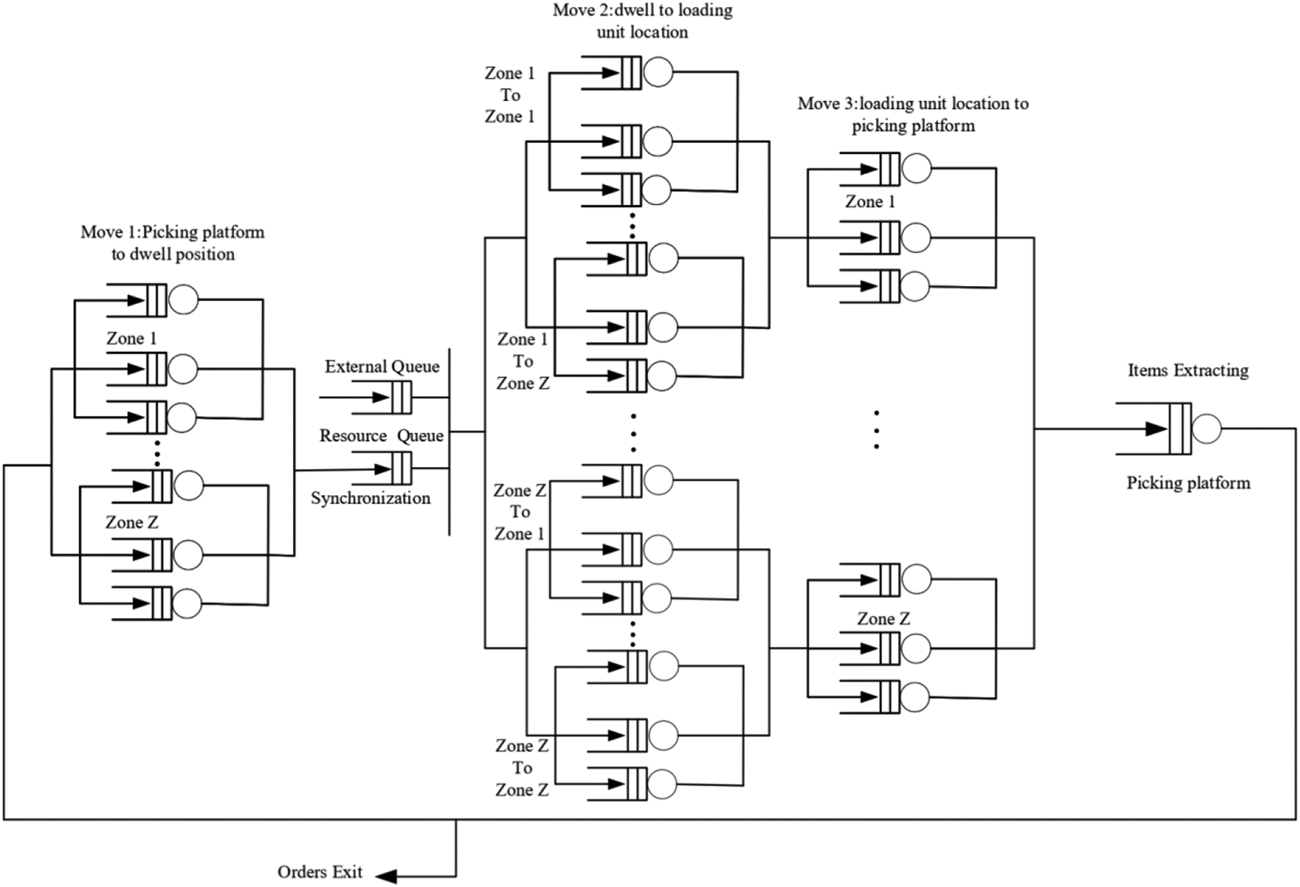
SOQN model with storage zones of RMFS. RMFS: robotic mobile fulfillment system; SOQN: semiopen queue network.
Model analysis
According to whether the customer leaves the queuing system, the queuing system is divided into an open-loop queuing network system (open queuing networks (OQNs)) and a closed-loop queuing network system (closed queuing networks (CQNs)). Among them, OQN customers come from the outside and leave the system after completing a series of service processes and CQN means that customers are served in the system without leaving.
Based on the queuing theory to describe the model’s goods-to-person system, there are two sets of queues in this type of system—both externally arrived customers enter the system and leave after being serviced, and the queues, that is the robot queues, that always exist in the system. In theory, this type of system is called SOQN, in which vehicle queues exist as resources in the system.
This article refers to the solving method of Buitenhek et al. 16
(1) Create a CQN model
Step 1 concerns the establishment of a closed-loop queuing network model. The queuing network model is transformed into a closed-loop queuing network model with N nodes when the matching service station is moved out. The AMVA (algorithm) method can be used to solve the closed-loop queuing network model. We can obtain the task throughput
(2) Create a second CQN model
It aims to establish a second closed-loop queuing network model with N + 1 nodes. Suppose the single arrival rate
(3) Analyze the synchronization station individually
It is to analyze the matching service station individually and can obtain the performance parameters at the end. In this step, the Little Law and Utilization Law are commonly used as the rules for performance accounting in systems engineering. The laws can be used as a theoretical basis for performance calculation.
(4) Indicates the relevant parameters in the SOQN model
Firstly, the access ratio of node
Calculation of the average remaining service time
The average remaining service time of orders being serviced at node

Calculate the average waiting time
After the order arrives, if the service equipment is busy, the waiting time will be generated. The waiting time is the average remaining service time of the customers that are serving at node

Calculate the throughput of the system
The throughput of a system is the number of tasks handled by the system per unit time

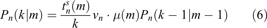
The probability that all robots are busy in node
The probability that all robots are busy at node

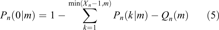
Calculate the probability that no robot in node
The probability that there are no robots at node
The average queue length
When the number of service devices exceeds the order number, the order does not need to wait and the average queue length is 0. If the number of service equipment is less than the order number, the queue length will be generated

The average queue length
According to the Litter principle, the average queue length at node

The second CQN model is calculated using the same logic as above.
In addition to the synchronization station, the sum length of each node is

Lamballais 7 used a simulation model to verify the accuracy and effectiveness of the AMVA algorithm based on SOQN analysis model for RMFS. Therefore, this solution is directly introduced in this article and does not verify it again. The theoretical efficiency of the solution is based on the assumption that the blocking factor is not considered. This is because the preceding assumption that aisles and cross-aisles have single directional travel everywhere, and the delays at the aisle and cross-aisle intersections do not occur. Therefore, the algorithm is practical in general.
Results
This section uses numerical experiments to analyze the influence of design structural factors on the order throughput of the system. The design factors include the width-to-length ratios of the warehouse, the combination of aisles and cross-aisles, the module size, the robot number, and the allocation of picking stations around the warehouse area. We designed an experimental platform using MATLAB firstly. Secondly, under the limitation of the specified square of the warehouse, we found the combinations of aisle and cross-aisle under the different module sizes and different width-to-length ratios. Finally, depending on whether the zoning strategy is considered or not, we did two experiments.
The experimental platform has been designed to estimate the performance of the system and to do the parameter configuration test in this article. This platform can be used to do the visual layout plan under all different schemes and parameter configuration.
Figure 7 shows that this platform includes the structure parameter configuration, zoning strategy parameter configuration, layout type selection, zoning direction setting, and result display.
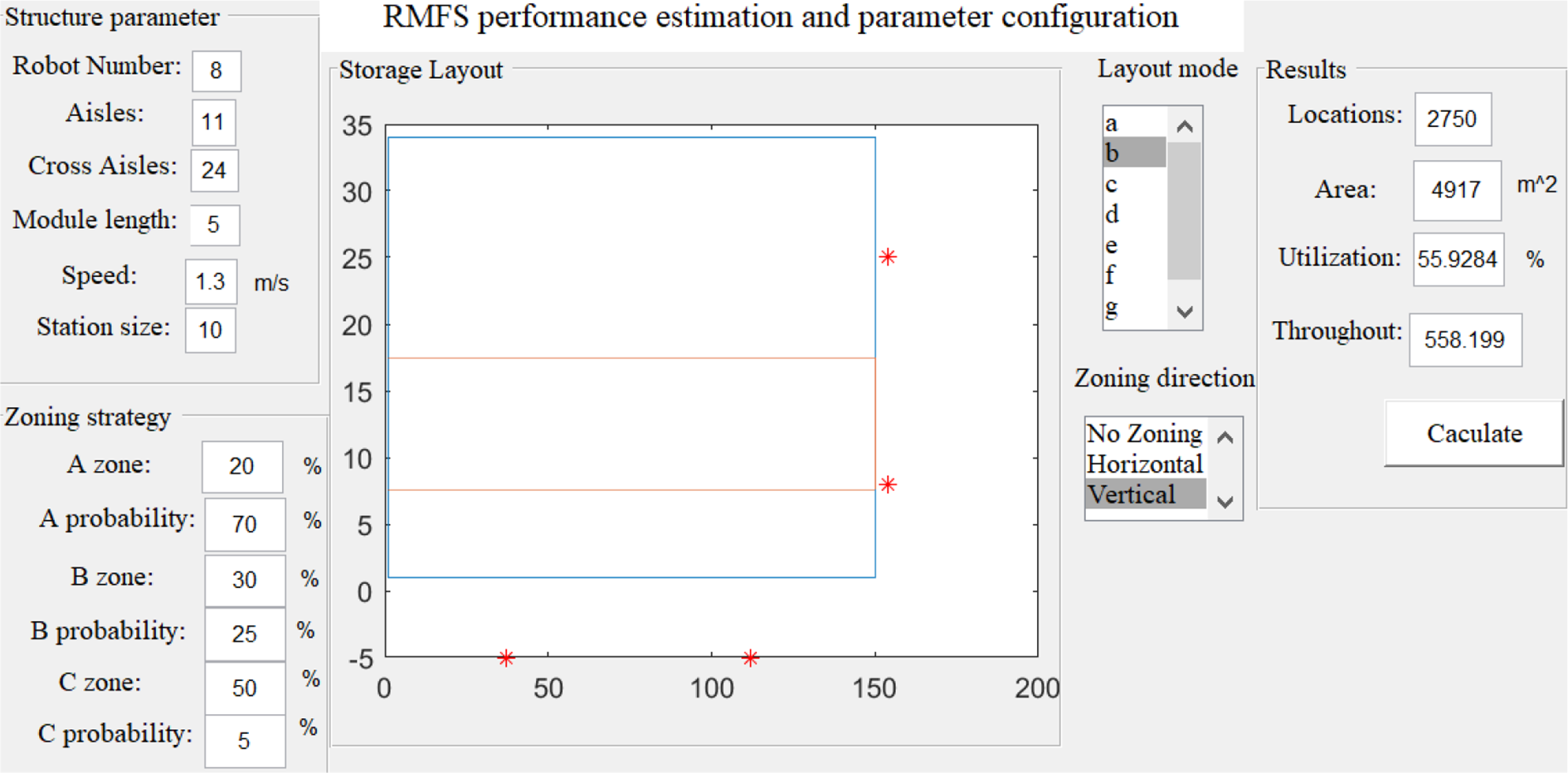
Performance estimation and parameter configuration experiment platform.
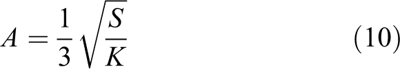
To compare the effect of width-to-length ratios and module size to the performance of the system, we got the formulas (10) and (11) to obtain the approximate values of aisle and cross-aisle according to Figure 2. To be practical, the count of aisle and cross-aisle should be an integer

After getting the combination of aisle and cross-aisle, we can calculate the real square of warehouse and its locations according to the formulas (12) and (13)


The square of the warehouse is limited to 5000. The width-to-length ratios are designed into seven groups. In practice, the width of each module Wm
equals 2 and the length of the module includes
To ensure the accuracy and validity of the experiments, we control the square of the warehouse for all combination groups keeping the range at
The tables above show that space utilization increases as the module size becomes larger. Besides, the space utilization of each group has a little change under the same module size and different width-to-length ratio. Therefore, the selected structural combination is valid.
Performance comparison without storage zones
This experiment is to compare the performance of the system under different structural combinations without storage zones. Figure 8 shows the data using the performance estimation platform to calculate the maximum order throughput when the robot’s number is 8 and 16, respectively. It illustrates the performance comparison result of seven layout modes.

Variants of module size: (a) Lm = 2, Wm = 2, (b) Lm = 5, Wm = 2, and (c) Lm = 10, Wm = 2.
In this figure, each row is the same module size with a different number of the robot. The left column in this figure, that is, Figure 9(a), (c), and (e) shows that the throughput of system is sensitive to the width-to-length ratio when the number of the robot is not high. Furthermore, the figures show that the trend for each curve is almost the same. Therefore, this conclusion is not affected by the module size or the allocation of picking stations around the warehouse area. In these figures, the system performs best during the width-to-length keeps in the middle three ratios (K = 0.67–1.5). This means as the closer of the length and width of RMFS, the throughput of the system will increase obviously.

(a–e) The performance comparison without storage zones.
In addition, the left column of Figure 8 shows the advantage of the internal layout over external modes. Two internal curves are all at the top of other curves in Figure 9(a), (c), and (e). This conclusion applies to the other module size design. The difference between the worst and best is over 22%. However, the right column, which is Figure 9(b), (d), and (f), illustrates that this difference will diminish as the number of vehicles increases due to the limited handling capacity of picking stations. Thus, the maximum order throughput is insensitive to the allocation of the workstation when the robot fleet is large. Nonetheless, this experiment proves that the internal layout design performs better than the external layout in general.
Depending on the conclusion above, we select the data that the width-to-length equals 1, and the robot number is 8 to compare their performance. This experiment can find how module size affects the RMFS.
Figure 10 shows that as the length of the module increases, the throughput decreases. This is because the number of cross-aisle increases when the module length is shorter. The advantage of the internal layout can also be seen in Figure 10. Although shortening the module can improve the order throughput of the system, it will reduce space utilization. Tables 2 to 4 present this difference. Therefore, decision makers should consider the throughput and space utilization comprehensively during the layout plan of RMFS. When the space is sufficient, and the requirement of order throughput is relatively high, they can shorten the module length to ensure high efficiency.

The performance comparison of different module size.
The structural combinations when

The structural combinations when

The structural combinations when

Performance comparison with storage zones
This experiment is to compare the performance of the system under different structural combinations with storage zones. In the experiments, the traditional ABC categorization is used for zoning. In practice, the zoning strategy storage distribution ratio is set as

The schematic of zoning direction: (a) Vertical zone and (b) horizontal zone.
It is similar to the previous experiment that the performance difference between different structural combinations will diminish as the number of vehicles increases. This situation is caused by the limited handling capacity of picking stations. Thus, we only choose eight robots to find how the zone strategy affects the performance of system.
Figure 12(a), (c), and (e) shows the vertical zoning experiment result with different module sizes. Figure 12(b), (d), and (f) shows the horizontal zoning experiment result. The left three subgraphs show when the width-to-length ratio is within a certain range, the system efficiency can be ensured to be at a high level. The best rates are the middle three which is in the range of 0.67–1, and the maximum order throughput reduces when the ratios are unbalanced by a factor of more than 3. The right three subgraphs indicate that the maximum order throughput keeps at a high level even when the ratios are diminished when using the horizontal zoning method. It is because the horizontal zoning makes entire locations more compact when the width reduces. This means that the performance of the system is affected by the width-to-length as a relationship to zoning direction.

(a–f) The performance comparison with storage zones.
According to the conclusions above, we select the data that width-to-length equals 1 and the module size is 5 to assess the zoning strategy. Figure 13 shows that using zones increases the maximum order throughput by almost over 50%. And the vertical zoning performs better than horizontal direction when the layout mode is the first three types. It has little difference between the layouts “d” and “e.”

The performance comparison with and without storage zones.
Conclusion
This article contributes to solving the problem of layout optimization under multiple structural parameters for RMFS. We proposed seven layout forms according to the relative location between picking workstation and storage area firstly. The queue network models have been created based on SOQN, as well as the performance estimation and parameter configuration platform, to calculate the efficiency of different parameter combinations. The first experiment shows that the maximum order throughput is sensitive to the width-to-length ratios when the robot fleet is not large. And the shorter module size can improve efficiency. The internal layout performs better than the external modes. The second experiment shows that using a zoning strategy can increase the maximum order throughput of RMFS. Furthermore, the performance is sensitive to the zoning direction, and the vertical partition is better than the horizontal zoning design.
There are some limitations in this article. We created the queue model considering the waiting time at the aisle intersection. But we simplified the model to get a solution using the algorithm. We assumed the paths are all in a single direction. In this assumption, the delay time caused by congestion can ignore, and the paths are all unlimited capacity servers to vehicle. In practice, congestion only has a small effect on the performance of RMFS. Because as one type of goods-to-person intelligent robotic warehouse, the design aim of RMFS is to keep pickers busy to extract items to achieve high picking rates. When the robot does not carry the rack, it would also travel underneath the racks. Therefore, the bottleneck of this system is the picker and not the robot’s transportation in general. However, it will be more practical to improve this algorithm to study how congestion affects system performance.
This article proposed two layout modes to put the picking stations into the warehouse area in this area. However, we did not study how the zoning strategy affects the performance of internal layouts. In addition, according to the conclusion in this article, the performance of the system is related to the zoning strategy and the module size. Therefore, it will have some further interesting optimization work to do when these two factors are taken into consideration. For example, the module size can be arranged small in zone “A,” which has a higher outbound frequency and lengthen the module size in zone “C.” We can continue this study in these challenging problems in the future.
Footnotes
Author contributions
SW brought up this subject and took on the main model design and the experimental data analysis; she wrote the original draft. CC mainly helped to do the data analysis and the following work of article review and editing. WW was responsible for reviewing and editing and validation of the experimental results. YW is the supervisor and guided SW to finish the conceptualization of the article.
Declaration of conflicting interests
The author(s) declared no potential conflicts of interest with respect to the research, authorship, and/or publication of this article.
Funding
The author(s) disclosed receipt of the following financial support for the research, authorship, and/or publication of this article: This work was supported by the Key Scientific Research Project of Shandong Province [No. 2017GGX60103].