
Abstract
Stand–sit–stand (STS) motions are the most frequently performed activities of everyday life and require extensive movement of knee joint. People suffering from knee joint disorders face difficulties in performing this motion. The compact knee exoskeleton (KE) has proven to be a viable, less complex, and cheaper alternative to the available entire lower-, upper-, and full-body exoskeletons. With growing number of technical glitches and finite battery life problems, there exist risks of sudden failure of the actuator of KE that could be detrimental for the vulnerable users. To overcome this problem, there is a need to accommodate a backup actuator in KE which can continue providing assistance during movement if the primary actuator ceases to function. This article provides a performance comparison of a four-bar mechanism-driven KE that can accommodate both the linear and the rotary actuators. The modelling and simulation of the system are performed using the bond graph (BG) technique. The results successfully showed that both actuators offered desired ranges of motions needed for STS motion. Furthermore, the knee joint torques developed by the linear and rotary actuators were found to be 40 Nm and 57 Nm, respectively, which corresponds to 60% and 85% of the total torque required by the knee joint to perform STS motions, thereby reducing the user effort to 40% and 15%, respectively. Thus, both actuators are self-capable to provide necessary assistance at the knee joint even if the primary actuator ceases to work due to a sudden fault, the secondary actuator will provide the required rotation of the thigh link and will continue to deliver the assistive torque. The article also effectively shows the application of BG approach to model the multidisciplinary systems like KE as it conveniently models the system containing various elements in different energy domains.
Keywords
Introduction
Knee joint is the most complex and stressed joint in the human body and, hence, is most susceptible to injuries. It carries weight of the body and absorbs the shock while carrying out activities of daily living. These activities comprise stand–sit–stand (STS) motions, walking, running, stair climbing, and so on. Nowadays, a large number of people suffer from direct or indirect knee injuries, which not only reduce their mobility but also affect their overall quality of life. 1 Over the years, many solutions were developed to assist such people. Some of them included the conventional knee ankle foot orthosis (KAFOs) and others were assistive devices such as wheelchairs and crutches, along with modern-day lower-body exoskeletons. 2 Despite providing some sort of assistance, generally, these conventional KAFOs could not provide the desired comfort which leads to unnatural motions. Furthermore, conventional assistive devices have also failed to provide complete independence to the users. With the recent advancements in technology, lower body exoskeletons appear to be a viable solution to this problem. 3 However, there still exist many challenges such as device’s weight, design complexity, unfriendly control graphical user interfaces, and limited battery life, which hinders the spread of the assistive exoskeletons. 4
To address these challenges, many research groups are working on improving the overall experience of the users who wear these exoskeletons. This article is specifically focused on comparing the performance of linear and rotary actuators in a knee exoskeleton (KE). The knee joint exoskeleton offers a lightweight solution and is capable to provide the desired assistance to cope with the reduced mobility problem. 5 Typically, KEs can be classified into two distinct types: (1) KEs used for gait rehabilitation of patients having knee impairments and (2) assistive exoskeletons for human performance augmentation of able-bodied individuals having cognitive weaknesses.
The patients with knee disorders might not be able to use their knees properly like normal people. Therefore, gait rehabilitation is required for these patients to restore their musculoskeletal strength and motor control. KE developed for rehabilitation can provide effective gait training in comparison to those of physical therapy. Beyl 6 proposed a KE named KNEXO, which is actuated by pneumatic artificial muscles. The gait timing symmetry helps the patient with KNEXO to increase confidence during walking. A four-bar linkage was designed for each muscle to keep the structure compact. In another work, a KE for gait rehabilitation was proposed by Kong et al. 7 who utilized rotary series elastic actuator (SEA) for the actuation. The SEA is composed of a direct current (DC) motor, a set of worm and spur gear, and a torsional spring. Mohammed et al. 8 proposed a KE for gait rehabilitation, which is actuated by a DC motor through a transmission mechanism comprised of a pulley, a ball screw, and a traction cable. In another work, a KE actuated by two DC motors in combination with five-bar linkage was presented by Liao et al. 9 Jain et al. 10 investigated the design of KE driven by four-bar mechanism using electromyography and force sensor for gait rehabilitation.
The KEs established for human performance augmentation could improve human strength and endurance during the motions such as walking, STS, and running. The energy can be saved for the wearer having such KE. Pratt et al. 11 developed a KE to augment wearer’s strength and to increase walking speed. The SEA was used to supply the required torque for the knee joint. Maeda et al. 12 developed a robotic KE to enhance human walking for healthy individuals. This KE is developed based on variable stiffness mechanism. The experimental results reveal that the muscle activity gets reduced by using the proposed design. Karavas et al. 13 adopted a tele-impedance-based control strategy to provide stiffness and motion augmentation by providing motion assistance. It detects a specific user’s intention for performing an activity, thus providing the desired torque. In another work, a KE consisting of a motor and a spring placed in parallel with leg for performance augmentation during transport was presented by Dollar and Herr. 14 A work on cable-driven parallel robot was proposed by Caffola et al. 15 to assist patients in rehabilitation exercises for both upper and lower limbs. The design was found to be essentially safer as it is driven by a cable and it possesses exceedingly low inertia.
The KE utilizing different actuators and mechanisms have been proposed by different researchers. Kamali et al. 16 investigated a KE actuated by linear SEA. The actuator comprises of DC motor, balls screw nut, timing belt transmission, and fiberglass spring. It was aimed at supporting people for STS motion. In another work, Trkov et al. 17 proposed a device for prevention of falling during walking. It consists of a set of compliant elements with impedance and torque feedback control. A commercially available KE PK100 powered by motor for neurorehabilitation and orthopedic physical therapy to increase the balance and to strengthen the weak muscles was proposed by Horst. 18
Various designs of KE composed of different mechanisms driven by mechanical linkages have been proposed by different researchers. An analysis of different mechanisms based on combinations of passive and active actuators was demonstrated by Noh et al. 19 Godoy et al. 20 proposed an exoskeleton based on eight-bar linkages for assisting people facing difficulties in walking. Each leg is based on a mechanism possessing single degree-of-freedom (DOF) linkage to be used as a robotic leg. In another work, Kim et al. 21 proposed a robot based on four-bar mechanism for the knee joint rehabilitation of the knee lesion patients. A four-bar mechanism was designed based on human knee joint’s four-bar link structure. It relies on the principle that the trajectory of the instantaneous center of rotation (ICR) of human knee joint varies with the lateral distance. A linear actuator for the actuation purpose was utilized for the actuation. Olinski et al. 22 proposed a 3-DOF system to perform the reference path of ICR of knee joint. The device was based on four-bar mechanism having controlled variable lengths of rockers for knee joint rehabilitation of the wearer. Kim et al. 23 proposed a passive mechanism based on four-bar linkage for load-carrying augmentation. A movable ICR mechanism was developed for the knee in lower body without using mechanical elements. In another work, Kim et al. 24 proposed an energy-efficient KE for load-carrying augmentation driven by four-bar mechanism along with an elastic element. However, these mechanisms still lack adjustable size, position, and orientation to accommodate wearers of different body profiles. Barjuei et al. 25 showed the advantages of bond graph (BG) technique to model the exoskeleton’s actuator that consists of brushless DC motor to have better insights of the system dynamics. Flynn 26 performed the synthesis of lower limb exoskeleton for clinical rehabilitation using BG modelling technique.
Based on the above literature survey and to the best of authors’ knowledge, no literature has been found regarding performance comparison between linear and rotary actuators based on their ability to provide assistive torque at the knee joint during STS motions of four-bar mechanism. This comparison is crucial to design a KE that accommodates both these actuators for the case when primary actuator ceases to work due to shorter battery life or owing to sudden fault. The idea of incorporating a secondary actuator is important as majority of the end users of the KEs are vulnerable persons and having a backup actuator will enhance its reliability and safety aspects. In this scenario, the secondary or the backup actuator must not only be able to provide the necessary rotation to the thigh link but also it should be able to provide sufficient torque to the knee joint of the exoskeleton to complete the desired STS motion. Furthermore, as per author’s knowledge, very few literatures are available on the BG modelling technique, which has been used to model the dynamics of exoskeleton systems and specially those focusing on the knee joint. Thus, it remains a lesser-explored concept to model a multidomain system like KEs.
BG is an extremely useful technique as it emphasizes on physical modelling and helps in understanding the behaviors of the system. Also, this technique not only supports modelling but also sensitivity analysis, model-based control, and model-based fault diagnosis of multidisciplinary engineering systems as well, as stated by Borutzky. 27 Since the present work can be extended to implement the fault detection, isolation, and reconfiguration (FDI) in the proposed exoskeleton. Therefore, it becomes crucial to model the multidomain system like KE in the present work by using the BG technique. BG offers multiple advantages with its application to any dynamic system. Being a topological modelling language, it can be used to model any multidomain system. It consists of only seven elements and thus proving to be very compact in nature. Since it is modular in nature, the modelling of an intricate system can be achieved by modelling the simpler subsystems. In this work, the actuator and the motor lie in the electrical domain, whereas, the gearbox, lead screw, and four-bar mechanism stay in the mechanical domain. Such multidomain systems can easily be modelled using BG and the present work shows useful application of this technique.
Thus, in this article, dynamic modelling of the KEs driven by a linear and a rotary actuator is performed. The modelling and simulation of both the KE driven by four-bar mechanism, the one powered by linear actuator and the other by rotary actuator have been performed using BG technique and Symbols Shakti software, respectively. The comparisons have been drawn for the assistive torque provided by each of these actuators at the knee joint of the KE. Furthermore, the angle of rotation of the links of the four-bar mechanism have been calculated and compared to ensure the rotation of thigh for the targeted STS motion. Therefore, the present work essentially shows that both the actuators are self-capable to provide the required support to the wearer for the STS motion. Furthermore, the application of BG approach to model the multidisciplinary systems like KE proved to be effective as it conveniently models the system containing various elements in different energy domains.
The rest of the article is organized as follows: the second section discusses the dynamic model of the human-exoskeleton system that includes the kinematic and dynamic model of the KEs. The third section describes the results and discussion, whereas the fourth section includes the conclusions and scope for future work of the article.
Dynamic model of a human-exoskeleton system
The cycle for stand to sit motion is shown in Figure 1. The cycle starts at the position when the thigh is at the angle (α3) of 1.7° away from the axis of shank (+ve y-axis) in the clockwise direction. For the sit position, the thigh rotates through an angle (α3+α2) of 85° in counterclockwise direction from the initial standing position. While in sitting posture, the thigh still makes an angle (α1) of 6.7° with respect to negative x-axis.
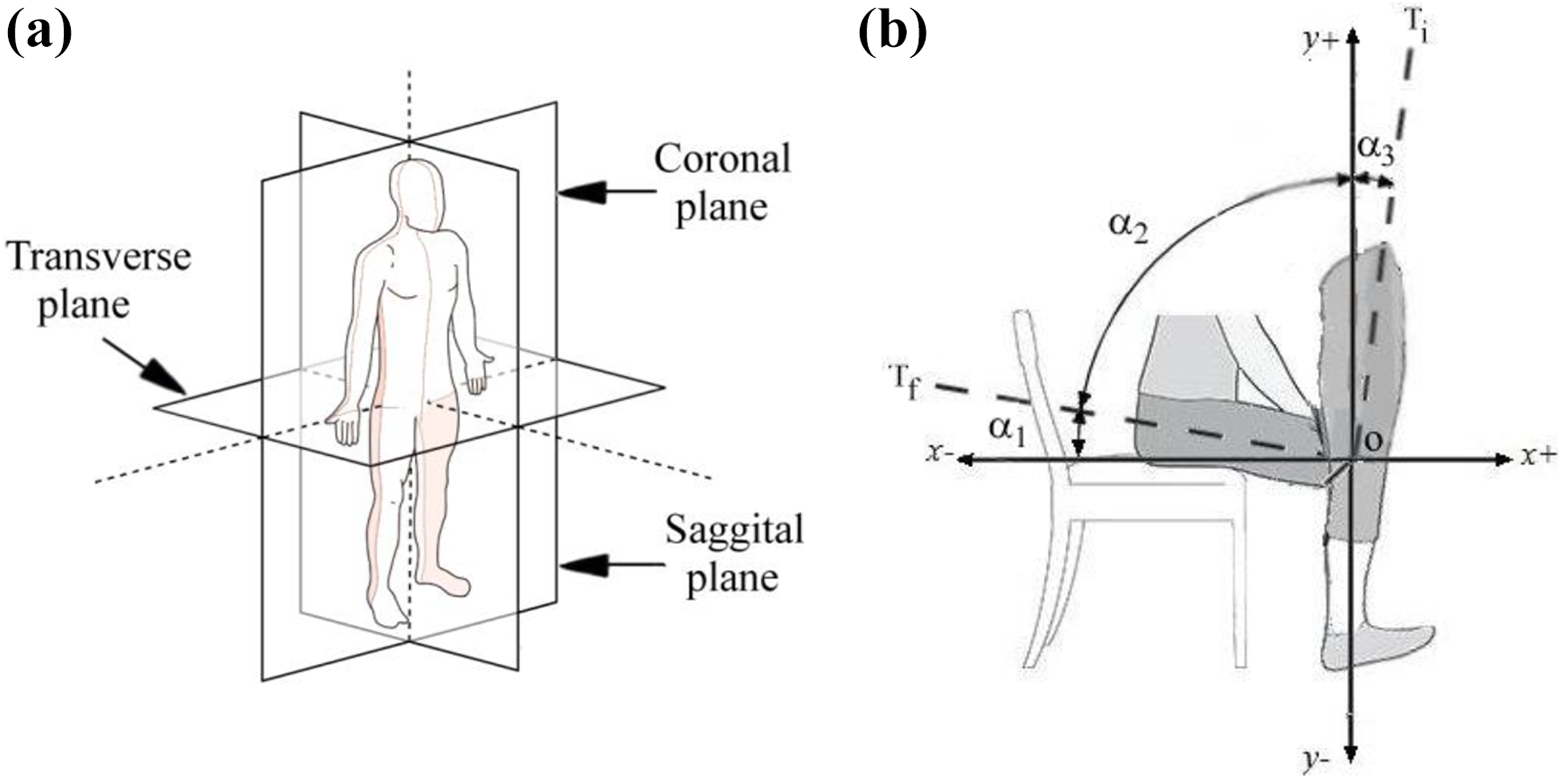
(a) Anatomical planes and (b) proposed STS motion. STS: stand-to-sit.
The KE driven by linear and rotary actuators are shown in Figure 2(a) and (b), respectively. The four-bar mechanism consists of links d 1, d 2, d 3, and d 4 constituting the four bars of the mechanism. In this mechanism, the sum of the shortest and the longest link (d 3 + d 4) is less than the sum of the length of other two links. Thus, it is a case of crank rocker mechanism as per the Grashof’s law, where the links d 3 and d 1 act as crank and rocker, respectively. The link d 3, which is the thigh link, rotates the human thigh, whereas the link d 4 is connected to calf, which remains fixed during the STS motion in the sagittal plane. The links of the four-bar mechanism are connected to each other through pin joints 1, 2, 4, and 5. The coordinate axis is located at joint 1 in Figure 2. The joint 5 is the knee joint of the exoskeleton whose axis is aligned with the user’s knee joint axis in the coronal plane.
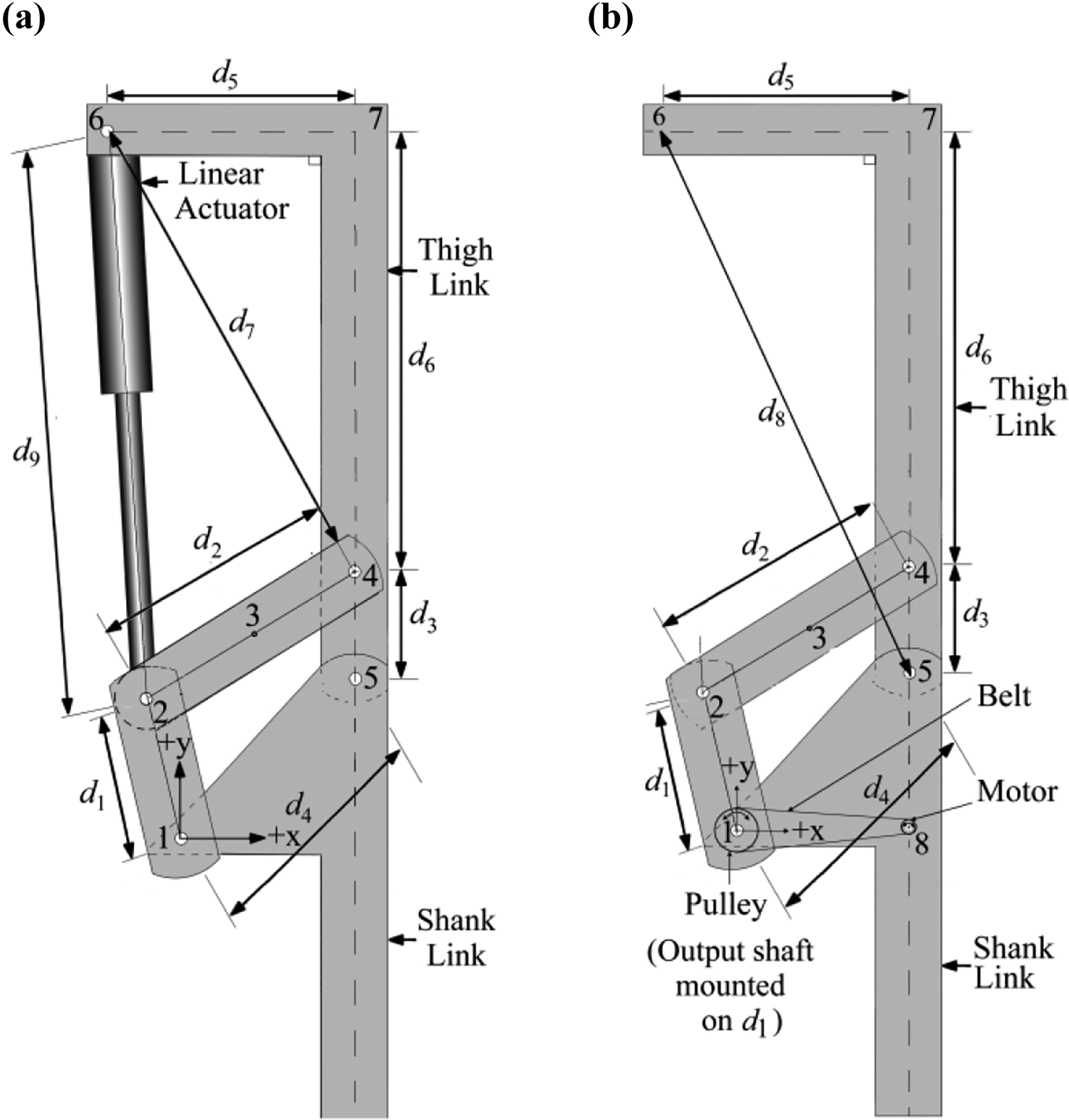
KE with (a) linear actuator and (b) rotary actuator. KE: knee exoskeleton.
In the KE shown in Figure 2(a), the linear actuator, which has a DC tubular motor, contains a displacement limit switch and has a self-locking feature. The circuit breaks when the telescopic bar runs to the top or to the bottom, thereby disconnecting the electric current automatically. The DC motor containing a lead screw drive propels the pushrod. The telescopic rod can only be retracted without rotation. If the positive electrode is stretched and the negative electrode is shrunk, the telescopic direction of the rod can be changed by changing the polarities. The joint 2 and joint 6 of the KE connect the piston rod end and cylinder end of the actuator, respectively. The actuator’s length is represented by d 9. Point 3 is the centroid of the link d 2. The linear velocities of joints 2 and 4 lying on d 2 are calculated with respect to the linear and angular velocities of point 3. Point 7 is not a joint rather it represents the point where the external load is assumed to be concentrated. Also, d 5 denotes the length of the link connecting points 6 and 7. The KE based on rotary actuator, which is a planetary geared DC motor, is shown in Figure 2(b). It allows the maximum-rated torque at lower speeds along with perfect position which is difficult to achieve with conventional DC motors, where, if motor speed decreases the output power gets reduced. The axis of the motor shaft is coaxial with joint 5 of the KE. Furthermore, the motor which is connected at point 8 of the exoskeleton drives the shaft with a belt pulley mounted at joint 1 as shown in Figure 2(b). This design is inspired from the work of Kim et al. 24 However, in the present work, the link lengths of the mechanism is designed on the basis of the actuator length in the compressed and expanded position, the angle of rotation of the link d 3, and the knee torque requirement at joint 5 of the exoskeleton for the desired STS motion.
BG models
The modelling of the KE with linear and rotary actuators is performed using BG technique. Certain assumptions are made before modelling; the joints of the four-bar mechanism in the exoskeleton are assumed to be as pin joints, the shank link lies in the vertical position during the STS motion, the inertial elements such as masses and moment of inertia are considered at the joints only, and the links of the KE are assumed to be rigid in nature.
The BG is a linear graph which is a pictorial depiction of a dynamic system. The nodes of the graph are multiport elements while the branches are bonds. It is a topological modelling language which can be used to model a multidomain system. The BG model in the graphical form is simulated by using the BG modelling software. 20 The key advantage of using this modelling technique is that only the kinematic equations are required to frame the BG model. The dynamic equations thus could automatically be derived from the simulation software. 21 Furthermore, only seven elements along with two junction elements are required to model the system. Thus, making it very compact. The inertial (I), compliance (C), and resistive element (R) are the single port passive elements, whereas gyrator (GY) and transformer (TF) are the two-port scaling elements. In this technique, the flows of signal are bidirectional and along the bond which is depicted by a line and a half arrow. The causal stroke describes the direction of flow of the effort signal. Furthermore, the causality of passive elements is fixed, whereas the junction elements are associated with constricted causality. Thus, the response of the system is obtained by properly assigning the causal strokes. 22 In this work, the actuator and the motor lie in the electrical domain, whereas the gearbox, lead screw, and four-bar mechanism exist in the mechanical domain. Such multidomain systems can easily be modelled using BG and the work shows useful application of this technique.
Figure 3 depicts the BG model of the motor and the lead screw. A DC motor is used as the source of power. The voltage (v) is supplied as input power source and is represented by the element, source of effort (Se) which is connected at 1-junction. The armature inductance and armature resistance are represented by inertial element (I) and resistive element (R), respectively and are connected at the 1-junction as the current is same (due to series circuit) for all the elements of the input electric circuit of the DC motor. The current (i) in the armature circuit is sensed by the current sensor which is represented by flow detector (Df
). The modulus of the GY
BG model of the motor with lead screw. BG: bond graph.
The BG model of the actuator is depicted in Figure 4. 28,29 The leadscrew (Figure 3) is the part of the actuator as shown in Figure 4. The input to the actuator as given in Figure 4 is the force imparted by the lead screw depicted in Figure 3. Figure 5 shows the BG model of the KE. The input at joint 2 of the KE (Figure 5) is taken from the output (force) of the actuator (Figure 4), whereas the output of joint 6 in the KE is connected with the cylinder end of the actuator (Figure 4).


BG model of the KE. BG: bond graph; KE: knee exoskeleton.
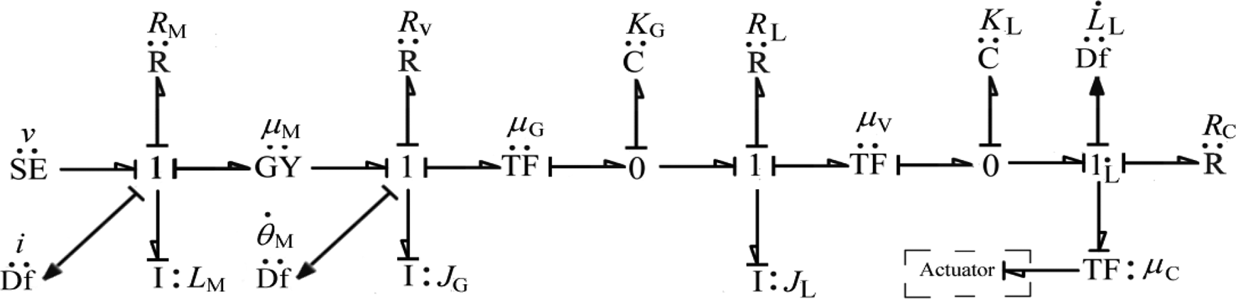
The BG model of the four-bar mechanism-driven KE with linear actuator is depicted in Figure 5. The actuator imparts input force at joint 2 of the exoskeleton where the piston end of the actuator is connected.
The zero sources of flow are attached at the 1-junctions through the coupling capacitor. K P and R P are the capacitive and resistive elements, respectively. These are connected in parallel mechanically at 1-junction. The Ses representing weight (W exo) of the exoskeleton and the external weights (W ext) are connected at 1-junction. This junction represents the velocities of joint 6. The Df measures the flow through the junction. The linear and angular velocities of joint 5 are measured using the Df connected at their corresponding 1-junction. The knee joint torque is basically the torque developed by the actuator at joint 5 of the exoskeletons. The forces acting at joint 1 of the exoskeleton are measured by the effort detectors. The normal component (with respect to the link d 4) of the force acting at the same point is calculated based on the force components and the angular position of the link d 4. Subsequently, the torque acting at the knee joint 5 is calculated based on the data obtained from the BG model.
The BG model of the DC motor (rotary actuator) is shown in Figure 6 while the BG model of the KE combined with a rotary actuator is shown in Figure 7. The angular velocities of joints 1, 4, and 5 are represented by
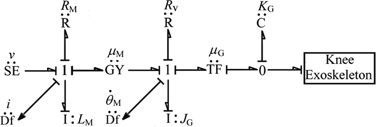
BG model of DC motor. BG: bond graph; DC: direct current.

BG model of the knee exoskelton driven by rotary actuator. BG: bond graph.
Results and discussions
The KEs actuated by linear and rotary actuators are simulated for the STS in a specialized BG simulation software Symbols Shakti. Different external loads W exo, (W exo + 20 N), (W exo + 40 N), and (W exo + 60 N) are added at point 7 of the KEs to check the efficacy of the current design to meet the minimum and maximum torques requirement for the STS motion, where, W exo = 28.86 N is the weight of exoskeleton and additional weight with W exo is the effective weight of the upper part of the user wearing KE. The major advantage of using the BG technique is that it is easy to model the system containing different elements in different energy domains and only kinematic equations are required to develop dynamic model of the system. The dynamic equations can easily be derived using software. The simulation time for a STS cycle is approximately 10.3 s. The parameters used for BG simulation of the KEs systems are specified in Table 1. Few parameters (of four-bar mechanism) are measured while others (parameters of the actuator) are either taken from the manufacturer’s catalog or from the product’s specifications. Table 2 represents the initial position for the exoskeleton.
Values of parameters used in BG models of KE.

BG: bond graph; KE: knee exoskeleton.
Initial position for the exoskeleton’s simulations.

Figure 8(a) and (b) shows characteristics of current for linear and rotary actuators during stand–sit motion simulations for different loads. Just at the start of the stand–sit motion, an initial spike in the motor current is observed for each load. The current in the motor peaks at 8 A and then drops to zero in 1.5 s. As the time increases, the current drawn by the motor starts to increase again and reaches 4.8 A, before settling down to 3.8 A, in 5.15 s, for all the loads as depicted in Figure 5(a). For the case of rotary actuator, there is a sudden surge in the current. The current reaches the maximum value of approximately 15.4 A and then becomes constant for the entire duration of the stand–sit transfer.

Motor characteristics (current) for stand to sit position (a) linear actuator and (b) rotary actuator.
The initial current spike in the motor’s current as shown in Figure 8(a) and (b) is caused by the fact that the motor draws larger stator current to counter the increase in the mechanical load which causes conductors of armature to move slowly through the electromagnetic field. Thus, the back electromotive force (emf) is reduced. The reduced back emf allows a larger current to flow through the armature and this larger current increases driving torque. A slight increase in the motor current is observed for each load. Furthermore, the motor constant in the case of rotary actuator is 1.5 Nm/A and thus the value of the motor torque is 1.5 times the motor current unlike the case of linear actuator where the motor constant is 1 Nm/A as shown in Figure 9(a) and (b).

Motor characteristics for stand-to-sit position, that is, torque for (a) linear actuator and (b) rotary actuator.
The results for the angle of rotation of the links of the four-bar mechanism in the KE actuated by linear and rotary actuators are obtained. Figure 10(a) and (b) shows the angle of rotation of the d 1, d 2, and d 3 of the four-bar mechanisms for linear and rotary actuators during a cycle of STS motion where 10.3 s is required for the loads of We xo and W exo + 20 N.

Angle of rotation of the links for linear and rotary actuators with weights of (a) W exo and (b) W exo + 20 N.
Initially, the links d 1 and d 3 are at an angle of 1.77 rad (101.4°) and 1.54 rad (88.2°), respectively, from positive x-axis, before the start of the motion which is the stand position. With increase in the cycle time, the angle achieved by the links increases and reaches to the maximum value of 2.71 rad (155.3°) and 3.08 rad (176.5°), respectively, at 5.15 s. Therefore, the value of angles, by the links d 1 and d 3, to attain sit position are 53.9° and 88.3°, respectively. The final positions of the links at the end of the cycle at 10.3 s are 1.75 rad (100.3°) and 1.53 rad (87.7°), respectively. Thus, the total angles achieved by the links d 1 and d 3 during the complete STS cycle in 10.3 s are 107.8° and 176.6°s, respectively. The link d 3 is the thigh link which is responsible for the rotation of human thigh during the STS motion in the sagittal plane and the angle achieved by it is called joint angle. A marginal change in the angle turned by the link d 2 is observed for the entire STS motion. The total angle achieved by d 2 is 3.3° during the STS motion.
For rotary actuator based KE, the angles achieved by the link d 1, d 2, and d 3 during the entire STS cycle are 108.6, 3.72, and 176.78°, respectively. It is important to note that angles achieved by the d 1, d 2, and d 3 with respect to cycle time are approximately the same for the loads W exo and W exo + 20 N. This shows that both the linear and rotary actuators can provide the necessary range of rotations to the thigh link for the desired STS motion. Furthermore, when the KE is driven either by the rotary or by the linear actuator, the total angle achieved by the thigh link with respect to time remains same. Thus, it is found that both of the proposed actuators are capable of providing the desired rotation of the thigh link needed for the STS motions. Furthermore, simulations are carried out to estimate the desired knee joint torque, which is the torque developed by the actuator at joint 5 of the exoskeleton for the STS motion. Figure 11 shows the body postures of the wearer during the STS operation using the KE. It shows the angle of rotation of the thigh link (d 3) when the wearer performs the STS motion.

Body postures during the STS cycle with KE. STS: stand–sit–stand; KE: knee exoskeleton.
Figure 12(a) and (b) shows the knee joint torques developed by linear and rotary actuators, respectively, at different loads for the complete STS cycle of 10.3 s during simulation. As the cycle starts, an increase in joint torque is observed as time increases and reaches the maximum value at 5.15 s which is the sit position. The torque value starts to decrease as time progresses and reaches to the minimum at the stand position at 10.3 s. With increase in the load, the maximum torque developed by the actuator at joint 5 increases. This is due to the fact that as the transition from stand-to-sit takes place, the moment arm increases which results in the increase in the torque developed at joint 5 (knee joint) of the exoskeleton. The maximum values of the knee torques when the exoskeleton is driven by linear actuator are found at 10.93, 23.8, 31.24, and 39.7 Nm for W exo, W exo + 20 N, W exo + 40 N, and W exo + 60 N, respectively, at sit position at 5.15 s. Similarly, for the case of rotary actuator, the corresponding maximum knee torque values for different loads W exo, W exo + 20 N, W exo + 40 N, and W exo + 60 N are found as 20.17, 31.47, 44.25, and 57.21 Nm, respectively. For better understanding, the observed knee torque values at joint 5 are plotted with respect to cycle time for different weights. These weights are chosen to check the efficacy of the current KE design containing using two actuators to compensate for the varied torque requirements during the STS motion.
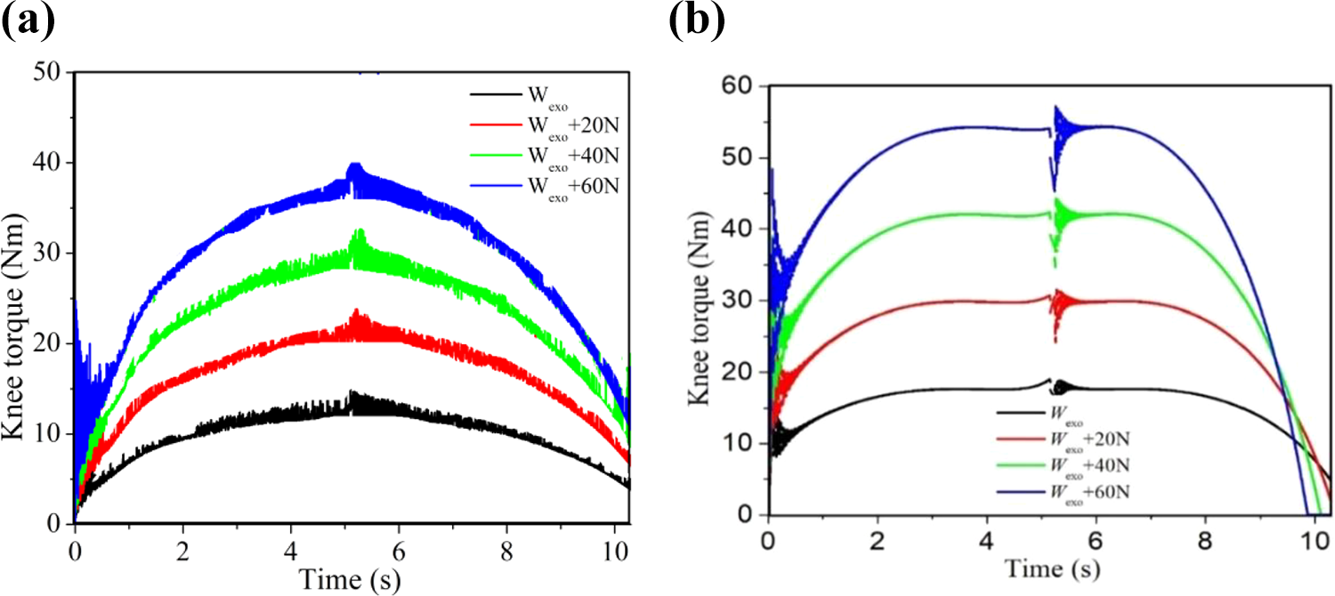
Knee torque versus time for different weights using (a) linear actuator and (b) rotary actuator.
Figure 13(a) and (b) represents the plots for the knee torque values with respect to the angle achieved by d 3 . for linear and rotary actuators, respectively, for stand–sit motion. The time required for stand-to-sit position is 5.15 s and the total time required for STS is about 10.3 s. Due to the uniformity of the graph in the second part, only the first part of the cycle is shown in Figure 13. It could be seen that the maximum torque is developed by the actuator at the sit position when the link d 3 (thigh link) has achieved a total angle of 88.3° from its initial stand position. The position of the link d 3 at the sit position is 173.3° from +x axis as shown in Figure 13. The maximum torque developed by the linear and rotary actuators is approximately 40 and 57 Nm, respectively. An initial spike in the knee torque is observed for stand–sit motion. This is because the motor exerts greater amount of torque to overcome the inertia of the link d 3 to be rotated as seen from Figure 13(a) and (b), respectively.

Knee torque versus angle of rotation of d 3 for different weights for (a) linear actuator and (b) rotary actuator.
It can be noted that the torque developed by the linear and rotary actuators at the knee joint is suitable to provide significant assistance to the user for performing STS motions. The maximum torque required for STS motion as per the literature for a healthy male of height 178 cm and mass 80 kg free from any musculoskeletal and neurological injuries is 67.2 Nm. 24
The KE based on linear and rotary actuators can deliver the maximum knee torques of 40 and 57.21 Nm, respectively, thus providing approximately 60% and 85% of the external assistive torque required at the knee joint for the STS motion, thereby limiting the user efforts to only 40% and 15%, respectively. However, the rotary actuator limits the user effort to minimal. Thus, either of the linear or rotary actuator is effectively capable to provide the required torque for STS motions in the proposed KE based on four-bar mechanism. Therefore, a KE for the purpose of reconfiguration is possible when powered by these two actuators.
Conclusions and future work
The dynamic modelling of the KEs driven by linear and rotary actuators has been studied in this work for STS motion using the BG technique in a specialized simulation software. The results are obtained for motor current and torque, angles of rotation of the links of the four-bar mechanism, and knee joint torque developed by the linear and rotary actuators when combined in a KE. It is found that both actuators provide same degree of rotation of the links of the four-bar mechanism with respect to the cycle time for STS motion. This proves that the present KE, when combined either with linear or rotary actuator, is capable to provide the required range of motions to the thigh link for STS motions. Furthermore, the found maximum torque developed by the linear and rotary actuators at the knee joint of the exoskeleton proves that the device may significantly assist the users during the STS transfer. However, the rotary actuator was found to limit the wearer’s effort to the minimal in comparison to that of linear actuator in the present design of KE. Therefore, for performing STS motion, the current four-bar mechanism is well-suited to accommodate both the linear and rotary actuators. The work provides a useful foundation to design a KE for the cases when the primary actuator ceases to work due to a sudden fault or battery discharge. In such scenarios, the secondary actuator must be able to provide the necessary actuation required for the desired STS motion. The BG approach to model the system proved to be quite useful as only the kinematic equations were required to model this multidomain exoskeleton system. The dynamic equations are automatically derived from the simulation software.
The future work is focused on the development of the exoskeleton prototype and implementation of the FDI and reconfiguration in the proposed exoskeleton.
Footnotes
Declaration of conflicting interests
The author(s) declared no potential conflicts of interest with respect to the research, authorship, and/or publication of this article.
Funding
The author(s) received no financial support for the research, authorship, and/or publication of this article.