
Abstract
Object recognition is a prerequisite to control a soft gripper successfully grasping an unknown object. Visual and tactile recognitions are two commonly used methods in a grasping system. Visual recognition is limited if the size and weight of the objects are involved, whereas the efficiency of tactile recognition is a problem. A visual–tactile recognition method is proposed to overcome the disadvantages of both methods in this article. The design and fabrication of the soft gripper considering the visual and tactile sensors are implemented, where the Kinect v2 is adopted for visual information, bending and pressure sensors are embedded to the soft fingers for tactile information. The proposed method is divided into three steps: initial recognition by vision, detail recognition by touch, and a data fusion decision making. Experiments show that the visual–tactile recognition has the best results. The average recognition accuracy of the daily objects by the proposed method is also the highest. The feasibility of the visual–tactile recognition is verified.
Introduction
Soft grippers made of soft materials have caused widespread concern for its capability of holding objects with various shapes, interacting effectively with unstructured environments, and performing tasks in a more dynamic manner. 1 –4 Until now, there have been a large variety of soft grippers, including those who are made from elastomeric pneumatic actuators, 5 –7 shape memory alloy (SMA)-driven, 8,9 shape memory polymer, 10,11 dielectric elastomer, 12,13 ionic polymer–metal composites, or electroadhesive polymer. 14,15 Among these, soft and smart materials were mainly applied and developed. Besides investigating the new materials, some research proposed a novel technique for direct 3D printing of soft pneumatic actuators 16 and fully multimaterial three-dimensional (3D) printed soft gripper. 17 With the innovations in material development, structural design, and manufacturing, the soft gripper has been utilized in building integrated systems for different application scenarios, such as rehabilitation 18 and assistance. 19 From the existing research on soft grippers, it is found that the majority are on the material and manufacturing techniques, the research on the practical application of the soft gripper are still deficient, which is, in fact, an important issue in constructing autonomous system regarding the soft gripper as the execution unit.
Object recognition is the first problem to be solved in the application of soft gripper. In general, visual and tactile recognitions are the fundamental approaches that are commonly adopted in the research on grippers. Visual recognition uses a camera to obtain the object image and identify the features. 20 In recent years, the accuracy of visual recognition has gradually improved with the progress of computer hardware and algorithms. 21 However, there are several factors that affect the performance of extracted features and limit the performance of vision-based methods, such as scaling, rotation, translation, and illumination 20,22 Moreover, some characteristics of the object, for instance, hardness, temperature, and weight, cannot be identified by vision. Tactile recognition receives information from the tactile sensors installed in the grippers. For example, bioTac sensors are adopted to obtain vibration of the object or texture of the surface to classify object material and shape. 23 –25 Angle and pressure sensors are utilized to analyze the bending information of the finger for recognizing different objects. 26 In summary, the influence of scaling can be removed in the tactile recognition as the real dimension and shape of the interacted object are mapped to the tactile sensor directly. In addition, tactile recognition can be used to capture properties like texture, roughness, spatial features, compliance, and friction, 27,28 which are difficult to be recognized by vision. Hence, it seems to be promising to adopt the tactile recognition in the autonomous system containing soft gripper. Since the existing tactile recognition methods are applied mainly to rigid grippers, there are two main questions if we want to apply them to the soft gripper: (1) Due to the infinite degree of freedom enabled by the soft material, tactile sensors for the rigid gripper might not be suitable for the soft gripper. The choice of available tactile sensors is limited. (2) Unlike the rigid gripper, whose motion and force feature are the main concern, the soft gripper also needs to consider the large deformation feature.
In the research community, there are some prior attempts to develop soft sensors for tactile recognition. She et al. combined a resistive flexible sensor with an SMA driver for curvature detection and feedback. 29 Chossat et al. applied ionic and liquid metals to develop highly flexible strain sensors. 30 A flexible “skin” sensor that could identify pressure and strains independently was invented. 31 Similarly, a flexible and extensible capacitive sensor was designed by Li et al., 32 and a soft optical sensor for measuring fingertip contact forces was proposed by Cho et al. 33 In all these works, soft sensors are designed for specific soft grippers with specialized materials and structures. They are expensive and might not be applicable to most of the soft grippers, thus hard to be utilized in the practical grasping tasks. A more promising and more efficient solution is employing the existing sensors to the recognition of soft grippers.
In the application of existing tactile sensors to the soft grippers, Homberg et al. 34 were the first ones to use bending sensors for a haptic recognition that provides configuration estimations to distinguish among a set of objects. Gandarias et al. 35 used the high-precision array type tactile sensor to detect the tactile images of the two-finger flexible gripper in contact with an object. Chen et al. 36 embedded the bending sensor into the soft pneumatic gripper and established the relationship between the diameter of the grasping ball and the output value of the bending sensor by curve fitting. In all these methods, plenty of experiments are implemented to capture accurate tactile information. They require strenuous effort if a wider range of objects are intended to be accurately recognized.
Having realized the pros and cons of the existing visual and tactile recognition methods, we come up with an idea to combine the two methods for low-cost, efficient, and accurate object recognition. A visual–tactile recognition method is proposed in this article. Visual recognition is firstly applied to a rough classification of the objects, which allows recognizing objects with obvious features like color and shape. Tactile recognition is then applied to achieve accurate identification by further assessing the property of the object, such as size and weight. To elaborate on the proposed recognition method, a self-developed soft gripper is adopted as the study object. The organization of the article is as follows. The second section briefly describes the structure and fabrication of the soft gripper, where the camera and embedded tactile sensors are introduced. The third section summarizes the proposed visual–tactile recognition method, followed which the vision recognition based on a faster RCNN 37 algorithm, and the tactile recognition based on a machining learning algorithm is illustrated in the fourth and fifth sections, respectively. The sixth section introduces the control system. The experiments are given in the seventh section before the conclusions are drawn in the eighth section.
Soft gripper and adopted sensors
Figure 1 shows a grasping robotic system consisting of an articulated serial robot and a soft gripper. The articulated serial robot is a UR3 robot 38 adopted for changing the position and orientation of the gripper. A Kinect v2 39 is selected as the visual sensor. As is shown in the figure, the Kinect v2 consists of a color camera, an infrared camera, and an infrared transmitter. The color camera is to obtain the RGB image of the view. The infrared transmitter emits infrared (IR), which will reflect if it touches the surface of the object. The reflected IR will be captured by the infrared camera. Judging by the time when to receive the reflected IR, the depth image of the objected is formed.

Grasping robotic system.
The proposed soft gripper has three fingers, which are actuated by the pneumatic actuators. As shown in Figure 2, each finger has an actuation part enabling the bending of the finger. The actuation part is composed of a multichamber and an inextensible layer. The former is made from silicone elastomeric material (Dragon Skin 30, Smooth-On Inc., Macungie, Pennsylvania, USA) and the latter is fiberglass mesh. By pumping air into the chambers, the pressure caused by the inflation of the chambers results in the bending of the fiberglass mesh. Considering the future tactile recognition, a perception part is designed to integrate the tactile sensors when fabricating the finger, in which bending sensors and pressure sensors are embedded.

(a) The structure of the soft finger, (b) bending sensors, and (c) pressure sensors.
As shown in Figure 2(b), Spectra Symbol 40 is selected to be the bending sensor, which is applied to capture the bending information of the finger. The Spectra Symbol deforms along with the fiberglass mesh. Its bending angle is converted to the change of resistance. The length of it can reach up to 95.25 mm, which is long enough to measure the bending of the finger. It has good flexibility and thus is suitable to be attached to the surface of soft material. Figure 2(c) shows the chosen pressure sensor FSR 402 by Interlink Electronics Inc., Westlake Village, Southern California 41 that obtains the force of two contacting surfaces during object grasping. The resistance of the force sensor decreases as the contacting force increases. The thin and bendable structure allows it to be embedded in the soft material.
The sensors are calibrated by experiments before embedding in the soft finger. The force sensors are calibrated by the strain dynamometer, where the output voltage of the force sensor is measured, as shown in Figure 3(a). With the increasing of the contact force, the resistance decreases and the output voltage increases accordingly. By exerting forces between 0 N and 10 N onto the pressure sensor, the corresponding voltage is measured. A cubic polynomial function is applied to fit the curve between the force and voltage as


Calibration of sensors: (a) pressure sensor and (b) bending sensor.
The input of the bending sensor is air pressure and the output is the voltage. When given certain air pressure, the soft finger bends and the curve is drawn, as shown in Figure 3(b). The voltage corresponding to this air pressure is measured. Hence, the bending information of the soft finger is demonstrated by the relationship between air pressure and voltage. The range for the air pressure is 0–60 kPa and for the output voltage is 1.74–2.26 V. As the air pressure increases, the voltage decreases.
The soft finger is made by casting. Instead of assembling sensors and the soft finger after fabrication, the sensors are directly embedded into the soft fingers during fabrication. As shown in Figure 4, the molds are 3D printed, with which the soft finger is cast step-by-step, that is, firstly, the actuation part and then the embedded sensor part.

Fabrication of the soft finger prototype.
The casting of the actuation part is summarized as follows: (1) Assemble molds A and B. Pour in the uncured silicone (Dragon Skin30, Smooth-On Inc., Macungie, Pennsylvania, USA). (2) Place the mold in a vacuum deforming barrel to remove air bubbles generated from the expansion. Heat the mold at 50–60°C for 40 min in a temperate box. (3) Cool down the mold at room temperature. The heating up and cooling down process is to speed up the solidification of silicone.
The casting of the embedded sensor part is shown in the following. (4) Pour the uncured silicone into mold C until it reaches the height 1.2–1.8 mm. This is to cast the base for sensors like the step 1. Repeat the heating up and cooling down process like step 2. (5) Attach the pressure sensors onto the base. Pour in the uncured silicone until the pressure sensor is covered. Repeat the heating up and cooling down process. Attach bending sensors onto the force sensor layer and repeat a similar process as above. On top of the bending sensor layer, put the fiberglass mesh and repeat the process as above. (6) The actuation part and the embedded sensor part are finally connected by the casting of uncured silicone.
Visual–tactile object recognition method
As mentioned above, visual and tactile recognition methods have their own pros and cons. Visual recognition is fast in localization, but accurate objective identification requires a camera with high performance and some features are difficult to be captured. Tactile recognition is precise in collecting the features and identifying the object. However, soft fingers are required to have one or more contacts with an unknown target object to obtain tactile information. The above entire process reduces object recognition efficiency. Inspired by the human perception process, which identifies object firstly by vision and then by touching and grasping, we propose a visual–tactile fusion recognition method for efficient and practical object recognition.
As shown in Figure 5, visual recognition is firstly applied for object localization and initial classification, which is realized by the depth image and the RBG image obtained by Kinect v2, respectively. A region-based algorithm called faster RCNN 37 is selected to extract the object features from the images and then classify these features by a classifier. If the object cannot be recognized from the RGB image, the characteristics obtained from vision recognition are not enough to identify the object. Due to the lack of information, similar objects would fail to be recognized. We define such objects as attribute missing categories, for instance, balls with the same color but different sizes or the same bottles with different volumes of water. To solve this problem, the tactile recognition is then applied.

The visual–tactile fused recognition method.
For the tactile recognition, N sets (rough within the range 70–100) of object grasping experiments are implemented to collect tactile information from the embedded force and bending sensors. The tactile information is stored in a vector of tactile features. The “bagged trees” algorithm is adopted as a classifier. Randomly, select n
1 sets of experimental data to perform the data training and cross verification. The
Herein, visual and tactile recognitions deal with their own data separately by a decision-making step. 42 The results from the visual and tactile recognition are fused on the decision-making layer as the final recognition conclusion. The object is expected to be accurately recognized by the combination of the two recognition methods.
Visual recognition based on faster RCNN
As has mentioned, Kinect v2 is applied to obtain the depth and RBG images of the object. Since the information on the location of the object is also aimed to be acquired for the grasping, a target algorithm called faster RCNN 37 is selected to address the problem of identification, classification, and localization.
In the faster RCNN model, the image is put into the convolutional neural network to generate a feature map. A region proposal network is then applied to come up with feature squares, from which the detail features are identified by a region of interest. The features are classified and the visual recognition results can be obtained. The details are carried out by the object detection API from Google as follows. Derive the images of the object. Label it by the LabelImg and transfer it into TFRecord format. Load the data training model Faster RCNN Inception ResNet v2. Modify the training model and create the explanation file. Train the data by TensorFlow and output the model. The GPU employed during training is the NVIDIA GeForce GTX 1080. Input the test image and obtain the recognition results. Compare with the real object and assess the accuracy. Repeat steps (1)–(4) and compute the average recognition accuracy.
To show the effectiveness of faster RCNN, another well-known visual recognition algorithm called SSD 43 is applied. The visual recognition based on SSD is similar to the procedure above. The difference is in the second step, where the model for data training in the SSD algorithm is SSD MobileNet v1.
Tactile recognition based on machining learning
The tactile recognition process can be divided into two steps. First of all, object grasping experiments are implemented. Data from the bending and force sensors are collected, from which the tactile features are extracted. Then, these tactile features are classified by the machining learning algorithms and the grasping object can be recognized.
Data collection
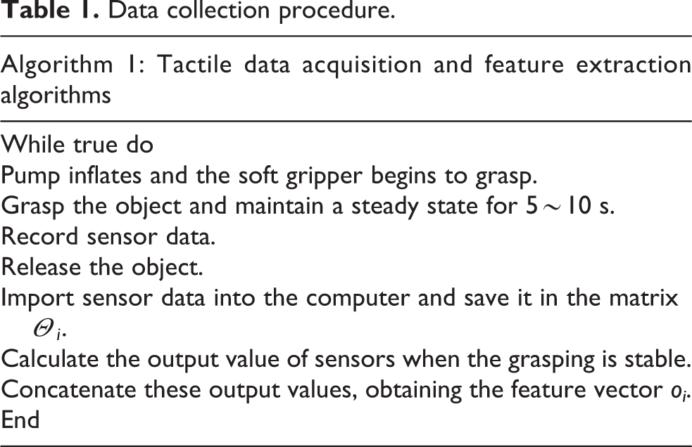
The process of tactile data collection is provided in Table 1. An object is handed to the soft gripper by the operator with different orientations and positions for better recognition robustness. The soft gripper gradually touches and grasps the object. After the object is successfully lifted, the soft gripper remains still for ∼5–10 s. The data from the sensors are recorded and stored in a matrix Θ i , where i represents i’th grasp experiments. The figure of the data in matrix Θ i is drawn, from which the steady state is recognized, and the corresponding values are kept in a vector oi .
Data collection procedure.
An example is given to illustrate the data collection process as follows. Ten pressure sensors and two bending sensors were embedded in the soft fingers. After holding the object 5–10 s, the data acquisition card started collecting the sensors’ data. The acquisition frequency is ∼20–50 Hz. The data were stored in the matrix Θ1, whose dimension is s × 12 (shown in Figure 6), where s is the number of frames in haptic sequence. The middle 100–150 values were roughly constant. This period is selected as a steady state, as shown between the dotted lines. The same experiment was repeated 70–100 times for different grasping poses, and the average of the values at steady state was calculated. Finally, the tactile feature vector o 1 is obtained as


Data of tactile sensors (F1: soft finger 1; F2: soft finger 2; FS: pressure sensor; BS: bending sensor).
Machine learning algorithms
After obtaining the tactile feature of the objects, machining learning algorithms are adopted to train and classify the objects. We applied five different machining learning algorithms, as given in Table 2. The decision tree algorithm 44 is easy to be implemented, in which three decision tree classifiers are used in feature processing. For the discriminant analysis, linear and quadratic discriminant analysis classifiers are studied. Support vector machine (SVM) 45 has been widely used in various classification problems and has achieved good results. Herein, six different SVMs are used in feature processing. The K-nearest neighbor (KNN) algorithm has also been widely used in current tactile recognition, 46 and six KNN classifiers are employed for comparative analysis. In addition, some classifiers integrated from different algorithms have good behavior in classification problems. 47 Five ensemble classifiers 48 are adopted. In total, 22 different classifiers are applied for analysis, from which the one with the best accuracy will be selected for fusion recognition.
Machine learning algorithms.

KNN: K-nearest neighbor; SVM: support vector machine.
Experimental verification
Visual recognition
In the visual recognition experiment, 20 different objects 28 that are commonly seen in daily life are selected, as shown in Figure 7 and Table 3. The objects are in different shapes, colors, sizes, and weights. Especially, the shape of the balls (C14, C15, C16, and C17) is the same but they are with different sizes (diameters are 63, 83, 98, and 120 mm, respectively). The color of C16 and C17 is the same but they are in different colors compared with C14 and C15. In addition, to test the recognition accuracy of the objects with the same shapes and color but different weights, the same bottle with different volumes of water is set. They are C18, C19, and C20.

Daily objects.
Twenty objects applied for visual experiments.

In the experiment, 2700 images of the objects are taken, in which 1800 images are used for training models and the remaining 900 images for verifications. The recognition results are provided in Table 4. Both models show acceptable accuracy if the objects are with distinguished shape and color (C1–C13, for instance). For the balls, C14 and C15 are well recognized but C16 and C17 could not be recognized by both models. For the bottles, the recognition accuracy of the SSD model is slightly higher than the faster RCNN model. However, neither of them reaches acceptable level. In conclusion, visual recognition is weak for the objects in different sizes and weights. Between these two models, the average recognition accuracy of the faster RCNN model is 80.78% (727/900), which is higher than the SSD model. Therefore, faster RCNN is chosen as the visual algorithm, and the tactile information is necessary for better recognition.
Recognition accuracy the SSD model and the faster RCNN model.

Tactile recognition
Tactile experiments are carried out on the same objects, as given in Table 3 and Figure 7. Each object is grasped by the soft gripper 70–100 times (see Figure 8), among which data of 50–70 times of grasping are regarded as the training set and the rest is the testing set. The training set is for the data training by machining learning algorithms given in Table 2. To avoid overfitting, a 10-fold cross-validation method 48,49 is applied to access the algorithms. The recognition accuracy is given in Table 5. Among the 22 classifiers of different machining learning algorithms, the average recognition accuracy of the bagged trees is the highest (87.8%).
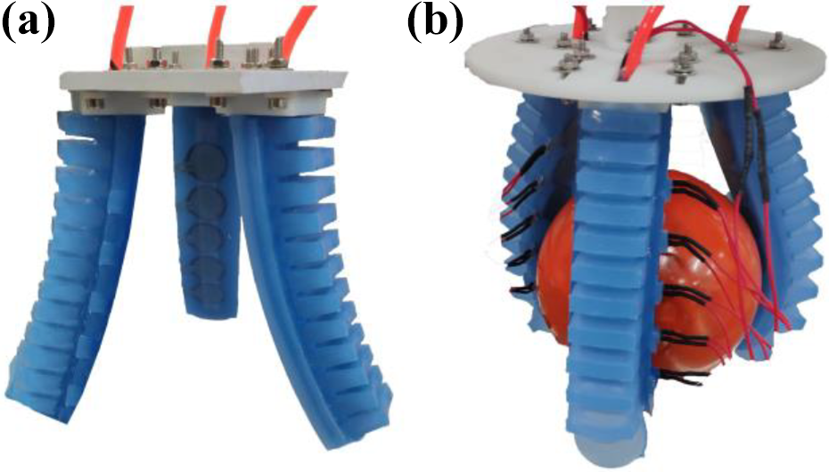
Three-finger gripper: (a) open state and (b) grasping state.
Accuracy of classifiers on the training data.
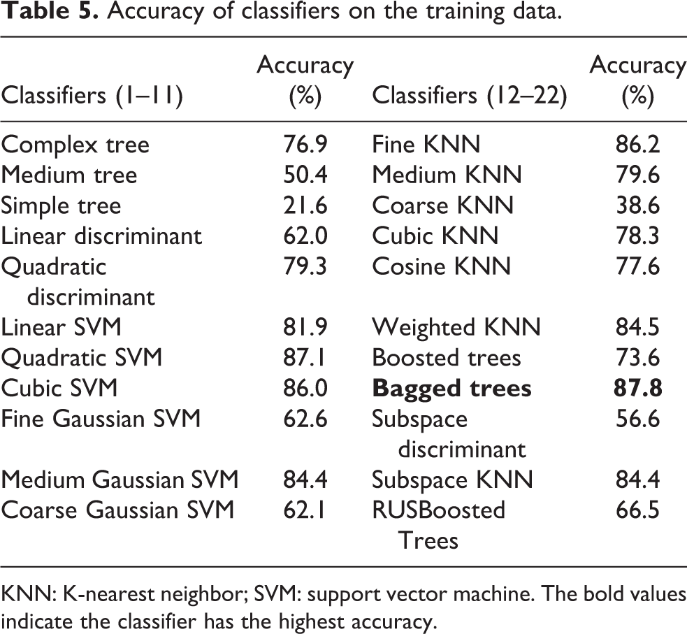
KNN: K-nearest neighbor; SVM: support vector machine. The bold values indicate the classifier has the highest accuracy.
The testing set is applied to further access the recognition of the bagged trees. An object category label can be obtained during the data training by the classifier on the training set. The value of this label is named as the predicted value. Similarly, an actual category label is defined by the testing set, of which the value is named as the actual value. These two labels are adopted to the 10-fold cross-validation method and a confusion matrix is generated. As shown in Figure 9, the horizontal axis denotes the predicted value and the vertical axis represents the actual value. The diagonal elements show the probability that the predicted and actual values are the same. By analyzing the confusion matrix, it is summarized that the average recognition accuracy of the bagged tree reaches 88.76% (545/614), among which apple (C1) and orange (C2), pencil sharpener (C5), and conditioner (C9) are 100%. In the visual recognition experiment, the objects with the same shape but different weights (C18, C19, and C20) failed to be recognized. In the tactile recognition experiment, the recognition accuracies of C19 and C20 are up to 91% and 94%, indicating that tactile recognition can distinguish objects with different weights. However, the recognition accuracy of C18, as well as the cup (C6) and ball 1 (C14), is less than 70%. The reason for this result might be that the information from the tactile sensors is not rich enough to recognize the objects with similar features, especially the objects with similar shapes, sizes, and weights.

Confusion matrix of the bagged tree.
Visual–tactile recognition
As has shown by the visual and tactile recognition experiments in “Visual recognition” section and “Tactile recognition” section, the visual recognition can efficiently distinguish objects with varied shapes and colors, but it is weak for the objects in different sizes and weights. The tactile recognition can solve the problem of size and weight. However, a lot of grasping experiments are necessary to collect enough information for better accuracy. To take full advantage of both the visual and tactile recognition methods, the visual–tactile recognition method is proposed in this article and the experiment is carried out in this section.
The same 20 objects are adopted again by the visual–tactile recognition experiment. As shown in Figure 9, tactile recognition is implemented to compensate for the missing attributes of objects after the visual recognition. Especially, the ball 3 (C16) and the ball 4 (C17) with the same color differ only in size. The empty bottle (C18), the half-full bottle (C19), and the filled bottle (C20) differ only in weight. The two groups of objects were difficult to recognize by visual and needed to be recognized by tactile. The trained faster RCNN model was used for visual recognition. Two tactile classifiers were used to recognize different sizes and qualities.
As shown in Figure 10, visual recognition is firstly implemented. If the object can be identified, the recognition results will be forwarded to the decision-making level. If not, the tactile recognition is carried out, where four classifiers are assigned. Tactile classifiers 1 and 3 are used for identifying the size of the object, while tactile classifiers 2 and 4 are applied for recognizing different weights. During the implementation of the visual and tactile recognitions, the respective procedure shown in “Visual recognition based on faster RCNN” section and “Tactile recognition based on machining learning” section is followed. The 10-fold cross-validation method is adopted to access the accuracy of the recognition results.
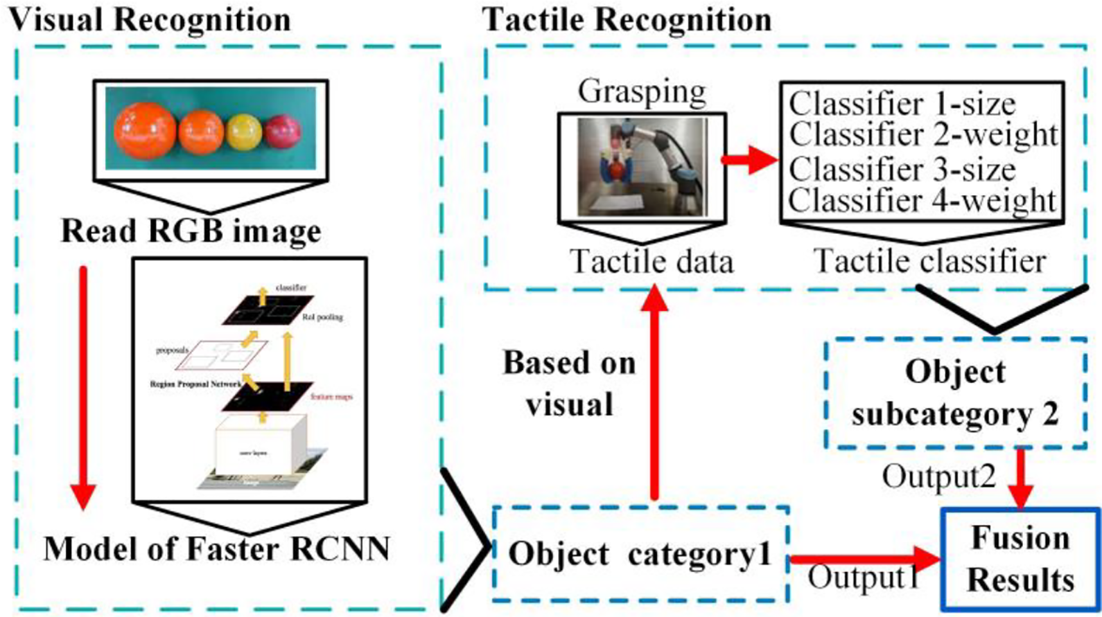
Experiments of the visual–tactile recognition (tactile classifier 1\3: identify objects of different sizes; tactile classifier 2\4: identify objects with different weights).
The accuracies of recognizing the 20 objects are accessed by the confusion matrix shown in Figure 11. On average, the accuracy is 98.70%, showing a good recognition result. Ball 3 (C16) and ball 4 (C17) fail to be recognized by the visual method. By combining the information from vision and tactile classifiers 1 and 3, the recognition accuracy of C16 and C17 is 100%. Similarly, the empty bottle (C18), the half-full bottle (C19), and the filled bottle (C20) cannot be identified by the visual recognition method. After recognized by the visual–tactile fusion method, the recognition accuracies of C18, C19, and C20 are all 100%. The recognition accuracy of balls and bottles is greatly improved compared with the accuracy of the tactile recognition method only. This might contribute to the combination of the information from both visual and tactile sensors. It shows that the visual–tactile fusion method at the decision-making level can make full use of visual and tactile recognition methods and improved the recognition accuracy of objects. The comparisons on the accuracy of different recognition methods are provided in Table 6. The average accuracy of visual, tactile, and visual–tactile recognition methods is 80.78%, 88.76%, and 98.7%, respectively, indicating that the best recognition results can be obtained by the visual–tactile recognition. For the objects with the same shape but different sizes, the accuracy of visual recognition is only 20%. It improves a lot by the tactile recognition, whose accuracy reaches 86.36%. However, the best accuracy is achieved by the visual–tactile recognition that increases 11.37% compared with the tactile recognition. Similarly, for the objects with the same shape and color but different weights, the recognition accuracy of visual recognition is the lowest (28.15%), followed by the tactile recognition (86.29%), and the highest accuracy is from visual–tactile recognition (95.97%). The results show that the visual–tactile recognition method can identify daily objects with high accuracy.

Confusion matrix of three-fingers soft gripper visual–tactile fusion.
Accuracy comparisons of different recognition methods.

Conclusions
A visual–tactile recognition method is proposed to efficiently and accurately identify the unknown object for a successful grasping of the soft gripper. A three-step procedure is presented, including initial recognition by vision based on the faster RCNN model, detail recognition by touch based on machining learning algorithm, and data fusion at decision-making level.
Considering the visual and tactile sensors, the design and fabrication of the soft gripper are first implemented. A Kinect v2 is adopted, and the RGB and depth images of the object can be collected. Bending sensors and pressure sensors are calibrated and embedded into the soft finger during fabrication, which turns the bending and contacting forces into resistance. For the initial recognition by vision, the faster RCNN is applied for classification and localization of the object. The identified results will be directly regarded as the final result if the object does not involve size or weight and can be fully recognized. If not, the detail recognition by touch is carried out. Machining learning algorithms are adopted to train grasping data. The information from both vision and tactile is finally combined at the decision-making layer, and the output is the recognition result. Experiments are implemented to verify the proposed method. The average accuracy of the proposed method is higher than visual recognition and tactile recognition, confirming the feasibility of the visual–tactile recognition.
Footnotes
Declaration of conflicting interests
The author(s) declared no potential conflicts of interest with respect to the research, authorship, and/or publication of this article.
Funding
The author(s) disclosed receipt of the following financial support for the research, authorship, and/or publication of this article: This research work was supported by the National Natural Science Foundation of China (NSFC) under grant no. 51675366 and Tianjin Technology and Science Plan Project under grant nos 18YFSDZC00010 and 18YFZCSF00590.