
Abstract
The long-range autonomous underwater vehicle is a new underwater vehicle with capability of stereoscopic observation of the ocean over a wide range of time series. This article proposed a novel control strategy for the long-range autonomous underwater vehicle considering the energy consumption. The vertical motion model of long-range autonomous underwater vehicle and the mathematical model of energy consumption of motion actuators are established in this article, and the maneuverability simulation experiments were carried out to analyze its motion and energy consumption characteristics. A hybrid controller based on human simulating intelligent control and S-plane control is designed. Considering the moment caused by the asymmetry of the hull in motion, an adaptive dynamic control allocation strategy is designed. Simulation experiments are conducted to demonstrate the performance of the scheme proposed.
Introduction
In recent years, underwater vehicles have been widely used in the fields of detection, military, and search and rescue and have played an increasingly important role. 1 –5 However, due to the limited energy of the traditional underwater vehicle, underwater vehicle’s endurance time and range cannot meet the needs of underwater missions with long time series and large range. 6 In order to improve the endurance of underwater vehicles, researchers have done a lot of work. Autonomous underwater glider (AUG) is a new type of underwater vehicle that achieves gliding by changing its buoyancy and attitude. It consumes very little energy and can perform long-range underwater tasks in the sea, such as Seaglider, Spray, and Slocum. These AUGs have been proved to have lower energy consumption and longer endurance. 7 –9 However, AUG can only voyage along the zigzag trajectory. Compared with the conventional autonomous underwater vehicles (AUVs), AUG’s speed is low and the maneuverability is poor, and it is difficult to adapt to the complex marine environment. In order to overcome the shortcomings of AUG, hybrid-driven underwater vehicles were developed.
The hybrid-driven underwater vehicles can work in three modes: AUV mode, glider mode, and hybrid-driven mode, 10 so it combines the high mobility of AUV and the long voyage characteristics of AUG, and it is the current research direction and hot spot.
AUV Tethys developed by Monterey Bay Aquarium Research Institute is one of the most successful LRAUVs. Its speed range is 0.5–1.2 m/s due to the use of propeller. It has been successfully applied to the investigation and research work in the Monterey Bay waters. 11 In literature, 12 a winged hybrid-driven underwater glider (HDUG) was designed. Considering the influence of internal actuators, the dynamics and kinematics equation models were established. The feasibility of the model was verified by experiments. The literature 13 used the HDUG Petrel-II as the research object and proved the stability of the HDUG controlled by buoyancy and propeller. In literature, 14 the Lagrangian method was used to establish a three-dimensional hydrodynamic model of a HDUG. The simulation results showed that the HDUG in AUV mode has the lowest resistance under neutral buoyancy and zero angle of attack.
It is also an effective means to reduce the energy consumption of the system to improve the endurance of the underwater vehicle from the perspective of control strategy. The control strategy not only guarantees the minimum range of motion but also needs to consider the optimization of the energy of the actors and energy consumption caused by the navigational resistance. 15 More and more control strategies and methods for reducing the energy consumption have been proposed.
In Xuliang et al., 16 a mathematical model of dynamic resistance for describing the relationship between AUV resistance and velocity was established, and the terminal slide mode control method is used to reduce the pitch angle and steering range of AUV. The simulation results showed that the pitch angle and steering range were effectively reduced. The pitch angle variance was reduced by 90.91%. The energy consumption caused by the extra resistance and steering was reduced. Literature 17 analyzed the energy consumption caused by overcoming the resistance and yaw. The self-tuning proportion integration differentiation (PID) controller based on multi-objective genetic algorithm was compared with the traditional PID controller. The results showed that the controller was with higher control efficiency and accuracy, lower yaw and roll amplitude. In Yao and Yang, 18 the multivariable generalized predictive control of AUV in low-speed near-surface was designed, which effectively suppressed wave disturbance and reduced the steering range, thus reducing energy consumption.
Although there have been related research studies on reducing system energy consumption and improving navigation performance of underwater vehicles, it can be seen from the literatures that most of the current research studies focus on optimizing drag reduction for navigational attitudes and optimizing control of a single actuator. The research studies on energy-saving hybrid control of long-range hybrid-driven AUV were not enough. It lacks theoretical analysis and research on the motion and energy consumption characteristics of actuators and lacks the proper control strategy and method based on the characteristics of each actuator. In this article, the vertical motion of the hybrid-driven underwater vehicle in AUV mode was studied. Considering the influence of shifting mass mechanism, the mathematical models of kinematics and dynamics were established, and the energy consumption models of actuators were established. The vertical motion controller was designed by combining the horizontal rudder and the shifting mass. The effectiveness of the control strategy and control algorithm is verified by simulation experiments.
This article is divided into the following parts: The second section establishes the long-range AUV vertical plane kinematics and dynamics model to simplify the linearization, establishes the vertical surface actuator energy consumption model, and analyzes it through maneuverability simulation test. The effects of different attitudes and different states of the actuator on system resistance were analyzed. The third section introduces the vertical plane motion controller and control strategy. Based on the characteristics of the actuator, the control strategy based on human simulating intelligent control (HSIC) and S-plane control is designed, and the adaptive dynamic control allocation strategy is designed. In the fourth section, the controller designed in this article is simulated by MATLAB in the presence of interference, and the simulation results are analyzed. The final section gives the conclusions of this article.
Models of LRAUV motion
The driving mechanisms of the LRAUV studied in this article are composed of a stern thruster, shifting mass mechanism, a buoyancy adjustment mechanism, a set of horizontal rudders, and a set of vertical rudders. The LRAUV is equipped with sensors such as doppler velocity log (DVI), depth gauge, and inertial measurement unit (IMU), as shown in Figure 1. This article will study the vertical motion of an LRAUV in AUV mode, that is, the state where the buoyancy adjustment mechanism adjusts the buoyancy to a suitable state and no longer works. In this mode, the adjustment of the depth and pitch angle is performed only by shifting mass mechanism and the horizontal rudders.

Structure of LRAUV. LRAUV: long-range autonomous underwater vehicle.
Definition of coordinate
For ease of problem description, two coordinate systems, inertial reference frame

Coordinate systems.
Dynamics and kinematics modeling
For the convenience of research, the following assumptions are made:
Assumption 1
The AUV is left–right symmetrical, and the shifting mass only changes the longitudinal position of the center of gravity, and the initial equilibrium position of the mass is
Assumption 2
The LRAUV performs vertical motion in AUV mode, which is in a state of zero buoyancy.
Assumption 3
The surge speed of the LRAUV is constant and the speed is 1 m/s.
Assumption 4
Ignore the effect of shifting mass acceleration on the AUV state.
Assumption 5
The pitch angle of LRAUV is small, so
Motion modeling
According to references, 19,20 the motion equations of the LRAUV can be written as

where

where

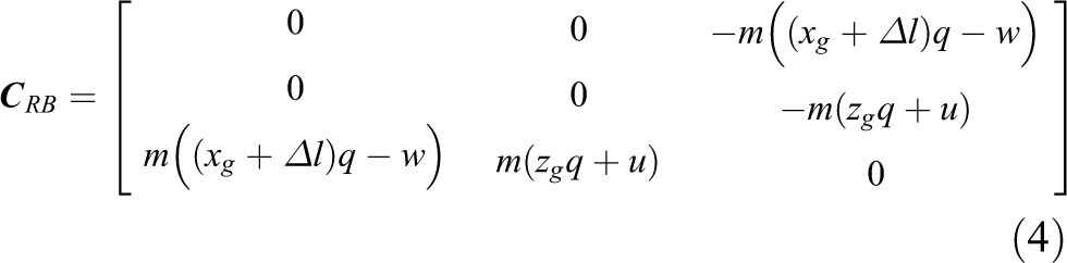


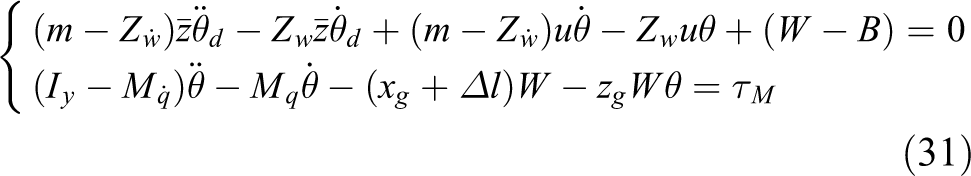
where M
0 denotes the pitch moment due to the upper and lower asymmetry of the hull.

where B denotes the initial buoyancy.
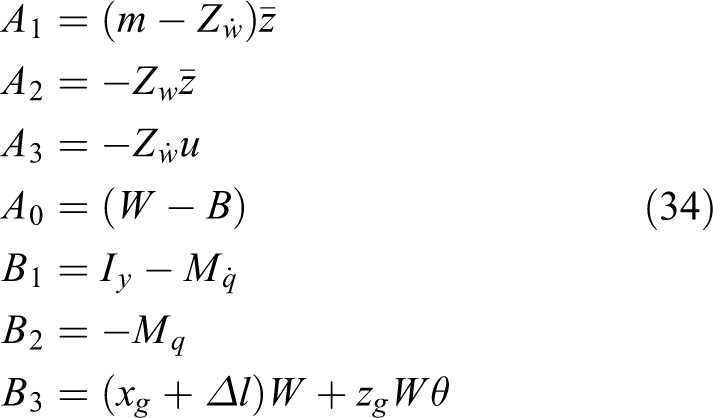
Define
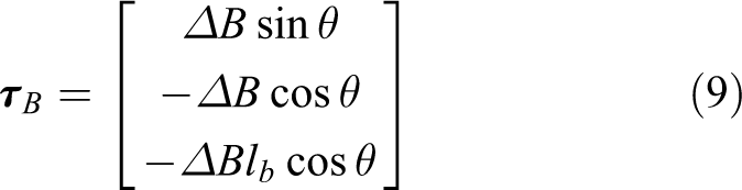
The moment generated by the shifting mass mechanism is

The control force (moment) generated by the rudder is written as
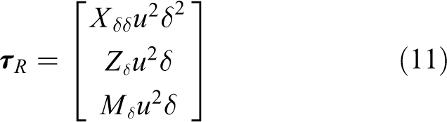
where
Let T denote the thrust, according to equations (9) to (11), we can get

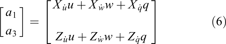
The main parameters of LRAUV are shown in Table 1. The hydrodynamic coefficient appearing in equations (3), (6), and (7) is calculated by computational fluid dynamics methods in FLUENT.
Main parameters of LRAUV.
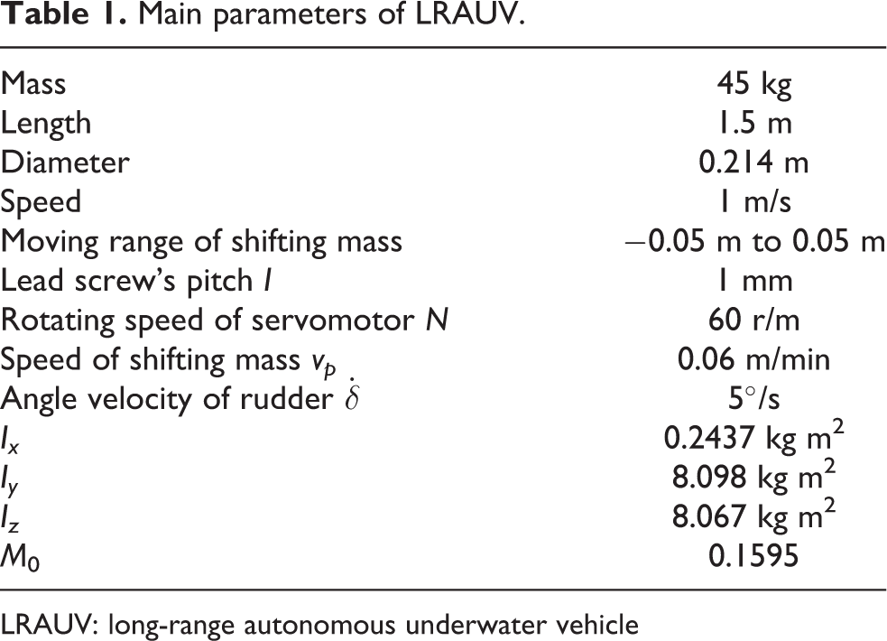
LRAUV: long-range autonomous underwater vehicle
Developing and analysis of energy consumption model
The models of energy consumption generated by horizontal rudders, shifting mass mechanism, and voyage are developed and analyzed in this section.
Rudder energy consumption model
The power of AUV’s rudder servomotor can be calculated as follows
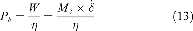
where


where
The work done from the rudder angle

where
In this article, the rudder deflecting rate is assumed to be constant. Hence, equation (16) can be yielded as

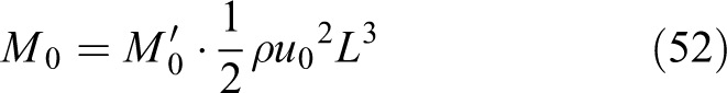
From the above equation it can be seen, when the speed is constant, the rudder energy consumption is proportional to the initial rudder angle and the quadratic of the rudder angle. The larger the initial rudder angle and rudder angle, the greater the energy consumed by the steering gear. Hence, try to steer the rudder around 0°, reduce the steering amplitude and frequency to reduce energy consumption.
Model of shifting mass mechanism
The shifting mass is driven by the cooperation of the screw and the servomotor to change the gravity center of the LRAUV. Assuming that the shifting mass center coincides with the center of gravity of LRAUV in the equilibrium state.
When the shifting mass moves, the torque T on the screw is

where θ denotes the pitch angle of LRAUV,
The power consumed by the shifting mass moving to

where P is the servomotor power,
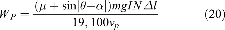
According to equation (20), we can get the conclusion that the energy consumption of a single movement of the shifting mass mechanism positively related to the moving distance and the AUV pitch. The greater the pitch angle, the more energy it consumes.
Additional consumption caused by resistance
According to Assumption 3, LRAUV moves at the constant speed v
0. If the surge drag changed, the thruster will consume more energy to keep the desired speed. Usually, the change of the AUV sailing resistance is mainly caused by the following two factors. Changes in navigational attitude of AUV. Changes of rudder angle.
The relationship between the attitude of the AUV and the resistance can be calculated by simulation. In literature, 14 it has been proved that the hybrid-driven underwater vehicle under AUV mode has the lowest resistance with zero angle of attack and neutral buoyancy. For the hybrid-driven underwater vehicle studied in this article, the resistance of AUV under different navigation attitudes is calculated by computational fluid dynamics (CFD) numerical simulation, which provides a basis for energy-saving controller designing.
Using the overlapping mesh method, the polyhedral mesh around the AUV can accurately represent the boundary of the object (especially the attached body) to ensure the calculation accuracy. To increase computational efficiency, a structured mesh is used in the area that is farther away from the AUV.
The mesh diagrams are shown in Figures 3 to 6. Figure 6 shows the AUV position in the flow field.

Mesh diagram.

Appendages mesh diagram.

Longitude mesh diagram.

AUV position in the flow field. AUV: autonomous underwater vehicles.
The simulations are performed to calculate the resistance of the angle of attack from −4° to 4° at a speed of 1 m/s. Simulation results are shown in Table 2. As can be seen from Figure 7, which shows the resistance with different pitch angles, the minimum resistance is 5.3 N at the pitch angle of 0°, the maximum resistance is 6.9 N at a pitch angle of −4° with the state of trim by bow. As a result, maintain the AUV at the 0° pitch angle or slight trim by bow state to get the lowest sailing resistance.
Simulation results of longitude drag with different pitch angles.


Resistance under different pitch angles.
To get the relationship between the pitch angle and resistance, the curve is translated downward by 5.3, that is, the resistance value of the different pitch angles with respect to the zero pitch angle can be obtained based on the resistance at the zero pitch angle. By fitting it by the least squares method, the approximate relationship between the pitch angle θ and the increase of longitudinal resistance

The rotation of the rudder not only causes a change in the pitching moment and the vertical force but also produces longitudinal resistance. The longitudinal resistance generated by the rudder can be expressed by the rudder’s drag coefficient

In order to keep the AUV sailing at a set speed, the AUV propulsion system must increase the thrust to balance the resulting resistance, and the increased energy consumption relative to the ideal navigational state can be expressed as

Maneuverability simulation experiment
Simulation experience on the above model is performed by using MATLAB. The surge speed of LRAUV is 1 m/s. The commands of rudder angle and shifting mass distance are as follows

Simulation results are shown in Figures 8 and 9. Figure 8 illustrates the comparison diagram of pitch angle response, and Figure 9 shows the comparison diagram of depth. As can be seen from the illustrations, the maximum pitch angle that the AUV can reach is 23.8° under the horizontal rudder control, and the maximum pitch angle that the AUV can reach under the shifting mass movement is 17.8°. The depth change of shifting mass is slower than the horizontal rudder, and the depth response curve of shifting mass is smoother. The pitch angle and depth responses of the shifting mass are different due to different time spent. The depth response under the shifting mass control has a significant hysteresis. Hence, the characteristics of the actors must be considered in controller designing.

Pitch angle comparison diagram.

Depth comparison diagram.
Figure 10 illustrates the relationship between the pitch moment and the rudder angle, and Figure 11 demonstrates the relationship between the pitch moment and the mass movement distance. The maximum pitch moment generated by the rudder is 2.29 N·m and generated by the shifting mass mechanism is 2.69 N·m.
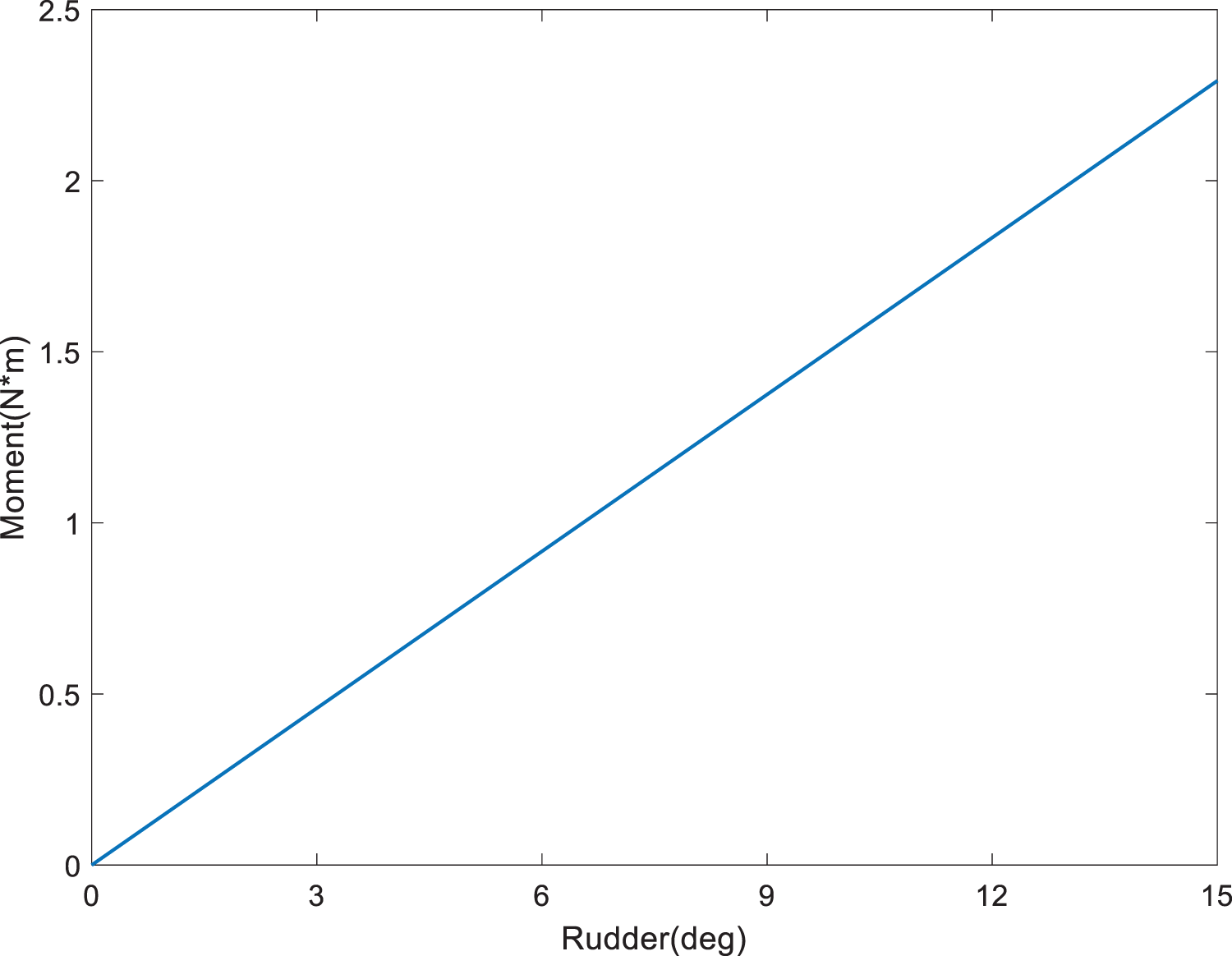
Pitch moment under different rudder angles.

Pitch moment under different distances.
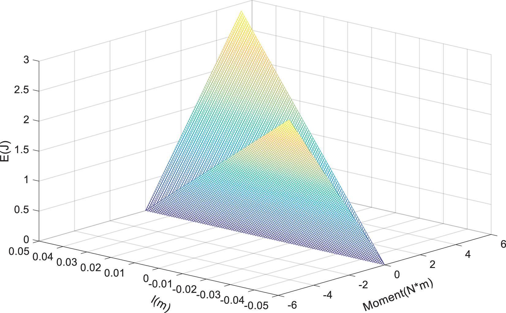
Figure 12 expresses the relationship between the pitch moment and energy consumption under the different initial rudder angle. As can be seen from the figure, the larger the initial rudder angle, the greater the energy consumption corresponding to the same control moment. The initial rudder angle at 0° produces a maximum control moment of 0.164 J, while at 15°, the energy consumption is 0.61 J. Figure 13 shows the relationship between the control moment and the energy consumption of the shifting mass at different initial positions.

Energy consumption under different initial rudder angles and moments.
Energy consumption under different initial positions and moments.
Therefore, when designing the controller, it is necessary to minimize the swing of the rudder under the large rudder angle and reduce the working frequency of the shifting mass mechanism, so as to reduce the system energy consumption and prolong the service life of the actuator.
Vertical motion controller design
The depth control of the LRAUV is essentially converted to pitch control, so the actual output on the vertical plane is the longitudinal force and the pitch moment about the y-axis. In this article, the LRAUV moves at a constant speed on the vertical plane, so the vertical controller only needs to generate the pitch moment. The mechanism for moving in the vertical plane is composed of a horizontal rudder and shifting mass mechanism, so it is a typical overdrive control in the pitch direction. It is necessary to design control allocation.
For the sake of modularity, the control allocation is separated from the high-level motion controller. As shown in Figure 14, the detailed knowledge of the actuator and the actual constraints on the actuator can be considered when designing the advanced control algorithm. Problems such as conditional and optimal control can be considered in the control allocation. High-level motion controllers to solve the pseudo-control inputs required by the system

Vertical motion control block diagram.
Ignoring the influence of the coupled motion, and the equations of heave and pitch motion can be obtained as

Due to the lack of heave control

Human simulating intelligent controller design based on virtual control signal
The main characteristic parameters in the control of AUV vertical plane motion are depth error ez and pitch angle θ. Under the consumption of constant surge velocity, depth change is mainly caused by the pitch angle. Hence, the rate of depth change can be expressed by the pitch angle. Process depth error into virtual control single

where
The vertical motion equation can be expressed as

According the above equation, we can get

Considering Assumption 5 and differentiate equation (29), we get

Substitute equations (29) and (30) into equation (26), the dynamic equations are yielded as
Introducing the error

According to the above equation,

where
Let

where

Then

A novel hybrid control strategy is designed in this article. Combine HSIC 22,23 and S-plane control 24,25 as a high-level control to generate the desired control moment.
In order to ensure the simplicity of the controller structure, only the bang-bang mode, the hold mode, and the S-plane control mode are involved.
The feature model of the HSIC operation control level is shown in Figure 15. ez
and θ respectively represent the normalized depth error and pitch angle. The dotted line indicates the ideal error trajectory

where
The control strategy selection steps are as follows: Generate the large control force when the depth error is large. When the depth error and the pitch angle are both small (deep-depth navigation or close to the target depth), the S-plane control modal control is adopted, except that the weights of proportions and differential of different regions are different. Maintain mode control is chosen when depth error and pitch angle are within a certain range.

The feature model of HSIC. HSIC: human simulating intelligent control.
Through the above analysis, the control model of nine regions can be obtained as

where
According to the characteristics of LRAUV’s actuators, the modal set of motion control is designed as

where
And the inference rules Ω can be determined as

where
According to the inference rules of the motion control, the output of vertical motion of the LRAUV can be calculated. For different stages, different control modes are used and different control parameters are adjusted. The critical thresholds of depth deviation and pitch deviation are mainly found through experience, and different regions are divided. This algorithm can imitate human observation and memory to make decisions, determine the control method through depth deviation and pitch angle, and finally make the entire system in reasonable control through different control modes. The normalized depth deviation and pitch angle threshold values in this article are shown in Table 3.
Thresholds of HSIC.

HSIC: human simulating intelligent control.
Design of control allocation
The control allocation is designed as

where

where
And the control allocation must meet the position constraints of the actuator

The discrete processing method of the computer enables the rate constraint to be processed by the control system calculation frame as a unit. Setting the sampling time of the control system as

where

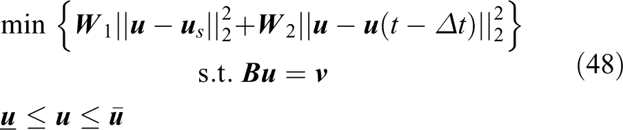
In this way, the control allocation problem with rate constraints is transformed into a position constraint problem within a unit calculation cycle. The control allocation problem is transformed into a secondary planning problem

where
The optimal dynamic control allocation expression is
where
There are countless solutions to the first constraint in equation (48). To find the solution that minimizes the index value, the optimal solution takes into account both needs as follows. Firstly, make the solution of the equation as close as possible to the value of the steady-state solution and then make the difference between the control command calculated at the current time and the value at the previous time smaller. The weight relationship between these two needs is reflected by the setting of the diagonal matrix
Set
Assuming that there is no saturation in the use of the actuator, the upper and lower limiting constraints of the actuator can be ignored. Solving this dynamic method can obtain

where
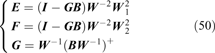
+ denotes the pseudo-inverse of a matrix.
The selection of weight matrix directly affects the control allocation effect. The larger the diagonal element values of the matrix
The selection of weight matrix
The control allocation process is shown in Figure 16.

Flowchart of control allocation.
When the AUV is voyaging at a fixed depth, due to the asymmetry of the hull, the fluid generates a pitching moment. The actuator generates a moment that respond to offset its effect. By offsetting the pitch moment by the horizontal rudder deflection at a certain angle, additional resistance will be generated, which is not good for energy consumption, so this article balances the pitch moment by the movement of the shifting mass. The pitching moment M
0 can be calculated from the hydrodynamic coefficient
And the distance of shifting mass can be expressed as

The control instruction after the control assignment is
Control stability analysis
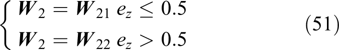
For the control method proposed in this article, bang-bang control and proportional control are used to reduce the system deviation faster. When the deviation is less than a certain value, the S-plane control method is used, so whether the final system is stable or not depends on the S-face controller. Applying the classic linear controller design method and selecting appropriate S-plane control parameters can ensure that the depth deviation converges to 0 within a finite time, that is,
We design the following Lyapunov function

then

When
Then the stability of control allocation is analyzed.
Theorem
Let

Proof
If equation (53) is asymptotically stable, then

Set

According to the equation

Equation (59) can be rewritten as

Therefore, if the desired control allocation us input to the control distributor is feasible and stable, the final control allocation will also be stable.
Numerical simulation
This section uses MATLAB simulation experiments to verify the method designed in this article. The AUV starts to move from a standstill, allowing the AUV thruster to sail at a constant speed and perform deeper motion.
First, under the ideal condition of still water, the simulation test of HSIC-based control algorithm is performed. Only the horizontal rudder was used for depth control, and the depth motion controlled by the S-plane method was used as the control group.
The simulation experiment of vertical plane motion under mixed control and dynamic control distribution is performed below.
Set diagonal matrices

In order to simulate the real marine environment and verify the effectiveness and authenticity of energy saving, a simulated wave force was applied to the AUV for simulation. Results are shown in Figures 17 to 20.

Response of depth.
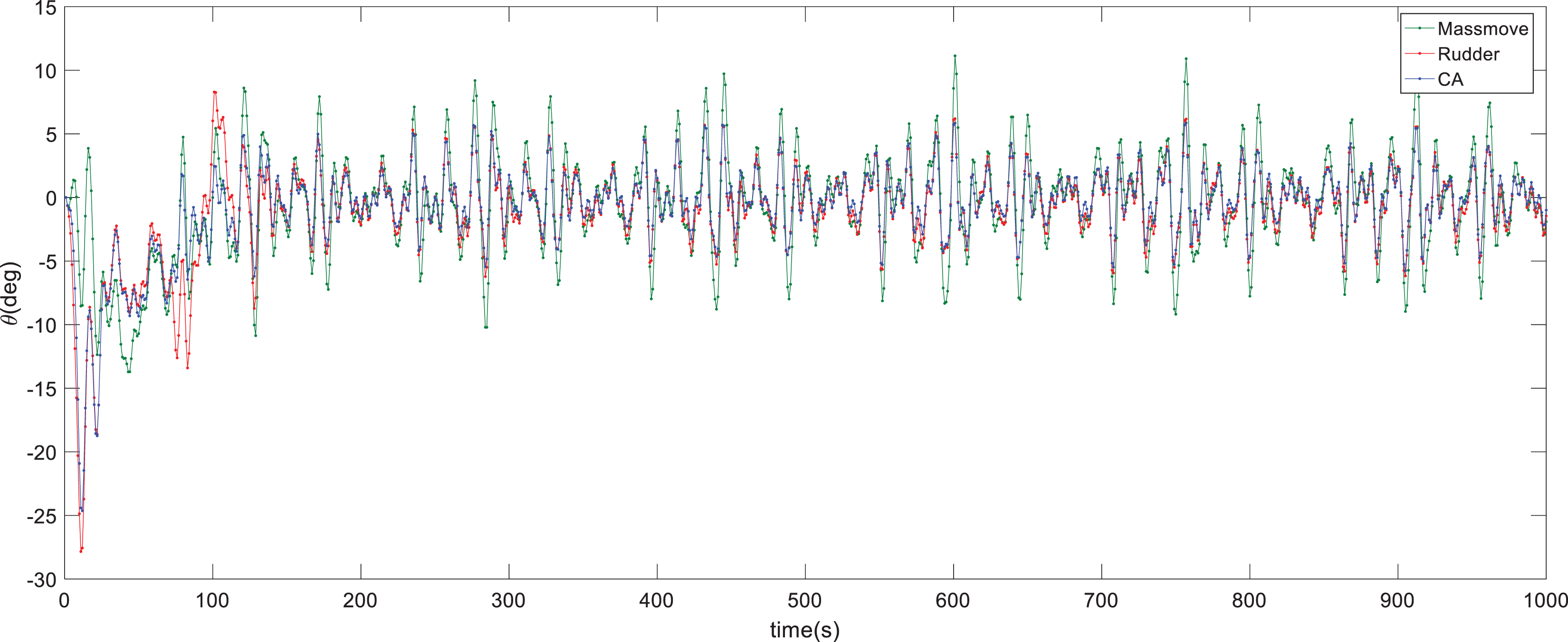
Pitch angle response.

Comparison of actors.
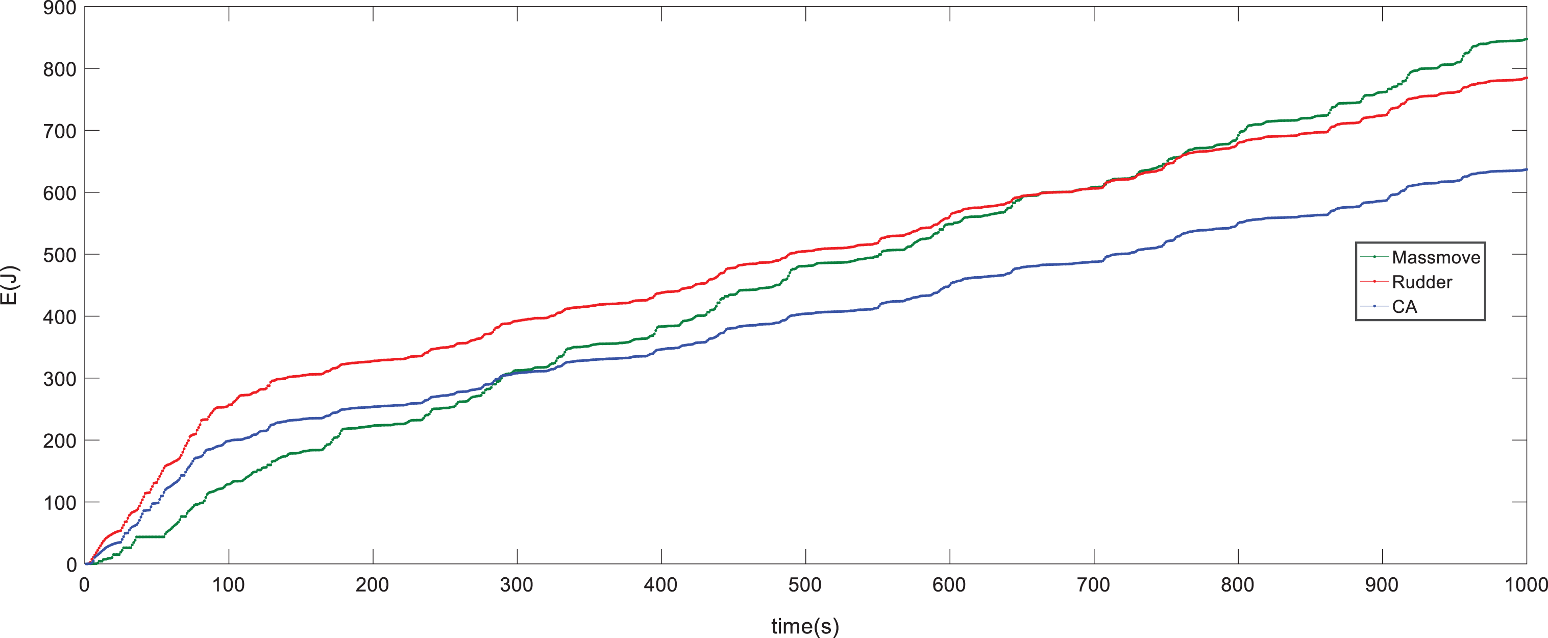
Energy consumption.
The control effect values are listed in Table 4. It can be seen from the simulation results that the overshoot is the largest under pure horizontal rudder control, and after the system is stable, there is a small steady-state deviation in the depth. This is because the depth deviation becomes smaller near the target depth. At this time, the output of controller is mainly affected by the pitch angle deviation and the pitch moment generated by the fluid, and the depth deviation is not sufficient to generate a sufficient rudder angle to eliminate the steady-state deviation. After the system is stable, the variance of the depth error under pure horizontal rudder control is the smallest, while the variance of the depth error under pure slider control is the largest. With reference to the second section of the maneuverability simulation test in this article, it can be seen that the depth response under horizontal rudder control is better than pure. In time, the two types of actuators participate in the hybrid control, so the depth error is between the two. The pitch angle variance under the hybrid control is the smallest, and the pitch angle variance under the pure slider control is the largest. This is because the trim response is slower under the pure slider control, and the trim angle cannot be effectively controlled. Under the hybrid control, the slider moves to the position where the pitching moment generated by the fluid can be offset; it can be seen from Figure 19 that during the fixed-depth navigation stage, the slider moves near the position of 0.004 m, which is the position to offset the pitching moment, and the rudder can respond to the pitch change in time and has a good effect on the control of the pitch angle. Under pure horizontal rudder control, the horizontal rudder not only needs to offset the pitch moment generated by the fluid but also needs to control the changes in depth and pitch angle caused by external interference. Therefore, the variance of the trim angle will be larger than that under the mixed control.
Control effect comparison.

Control energy consumption values are listed in Table 5. The energy consumption of each actuator under mixed control is smaller than the energy consumption of the corresponding actuator under a single control mode. The horizontal rudder energy consumption is reduced by 25.66%, and the slider energy consumption is reduced by 14.39%. The control is large, but the navigation energy consumption is effectively reduced. Compared to the pure horizontal rudder control, the navigation energy consumption is reduced by 21.65%. This is caused by two factors: The slider is balanced due to the asymmetry of the hull. During the whole process, the rudder angle has been reduced from 13.46% under pure horizontal rudder to 9.19% under hybrid control, a decrease of 31.72%. The rudder angle under pure horizontal rudder control works near 1°, while the rudder angle under hybrid control works near 0, which reduces the longitudinal resistance caused by the rudder angle. The range of pitch angle change is reduced, which reduces the energy caused by attitude. Changes in energy consumption. During the entire vertical plane movement, the total energy consumption of the hybrid control is reduced by 18.85% compared to the energy consumption of the pure horizontal rudder. Control energy consumption comparison (J).

In the running balance, a linear fit of the energy consumption curve under horizontal rudder and hybrid control can be obtained as follows

where ER
denotes the energy consumption of rudder mode and
Conclusion
This article studies the energy-saving control of LRAUV vertical plane motion. By analyzing the motion and energy consumption characteristics of the actuator, a vertical energy-saving control method and strategy are designed. Control is divided into two parts: advanced control layer and control distribution layer. At the advanced control layer, a new hybrid control method is proposed combining human-like intelligent control and S-plane control. At the control allocation layer, based on the theory of dynamic control allocation, a new control method is proposed, that is, An adaptive dynamic control allocation strategy. Simulation tests show that using the control strategy designed in this article, the long-range underwater vehicle can respond to changes in depth in a timely manner, and the control effect is good. The center of gravity moving mechanism can offset the generated pitching moment. After completing the vertical plane movement, the rudder angle of the horizontal rudder has been significantly reduced. The energy consumption model established in this article shows that the energy consumption of the control process is significantly reduced compared to the horizontal rudder control mechanism using pure S-plane algorithm. This is of practical significance for long-range underwater vehicles. Future work will continue to optimize control allocation and conduct pool and field tests on actual boats to further validate the designed control strategy.
Footnotes
Declaration of conflicting interests
The author(s) declared no potential conflicts of interest with respect to the research, authorship, and/or publication of this article.
Funding
The author(s) disclosed receipt of the following financial support for the research, authorship, and/or publication of this article: The work was supported in part by the China National Natural Science Foundation (nos 51779057, 51709061), and the Equipment Pre-research Project (project number 41412030201).