
Abstract
In recent years, the trimaran as a novel ship has been greatly developed. The subsequent large vertical motion needs to be studied and resolved. In this article, an experimental study for a trimaran vertical stabilization control is carried out. Three modes including the bare trimaran (the trimaran without appendages, the trimaran with fixed appendages, and the trimaran with controlled appendages) are performed through model tests in a towing tank. The model tests are performed in regular waves. The range of wave period is 2.0–4.0 s, and the speed of the carriage is 2.93 and 6.51 m/s. The results of the three modes show the fixed appendages and the actively controlled appendages are all effective for the vertical motion reduction of the trimaran. Moreover, the controlled appendages are more effective for the vertical stability performance of the trimaran.
Introduction
The trimaran has applied in the field of civilian, military, and rescue because of the excellent performance. For instance, a helicopter can be parked on the spacious deck according to the wide deck of the trimaran. Many investigation equipment can be loaded on the trimaran as a result of the good performance of antirolling. However, the two degrees of freedom vertical motion, including heave and pitch motion, may produce when a trimaran sailing in marine. Large vertical motion can cause seasickness, equipment failure onboard, and damage to the hull, 1 thereby reducing the performance of the trimaran.
According to a large number of research on the motion stability of monohulls, it is usual to install appendages like fin, rudder, and antiroll tank on the hull for antirolling. 2 –4 Likewise, in the vertical motion reduction of a ship, the appendages were generally selected as fin, T-foil, flapping foil, and trim tab. 5 –9 Due to the particularity of the structure and the requirement to reduce vertical motion, some commonly used appendages, such as antiroll tank and fin stabilizer, are not suitable for a trimaran. To reduce the vertical motion, it is more suitable to install appendages at the bow and aft because a trimaran is relatively long and slender. Combined with the commonly used types of stability appendages, T-foil and flap are used as the stability appendages of the trimaran. Also, the stability appendages are divided into passive and active appendages. The passive appendage is convenient and easy to install on a ship, but the motion reduction rate is not satisfactory in most conditions. Focusing on the above reason, active appendages are emerging and requiring a control algorithm to control the appendages.
Ship stability control belongs to the application of control methods in ocean engineering. Many control algorithms have been proposed in related ocean engineering applications, and these algorithms have been verified through simulation and experiments. In the study of Yang and Yin,
10
a novel sliding mode observer method is proposed, and the simulation results verified that the performance of the method is superior to the traditional control method. In Liang et al.’s study,
11,12
swarm control was proposed and performed for underactuated marine vehicles. Adaptive fuzzy fault-tolerant control, fuzzy dynamic surface control, and fuzzy backstepping sliding mode control were also applied in the controller design for marine applications.
13
–15
Model predictive vertical control of a passenger ship was studied by Kucukdemiral et al.
16
They designed a controller based on model predictive control. The controller has good performance compared to the other control methods (
In the model test or experiment, the required control method needs to be efficient, easy to implement, and robust. The controller based on proportional, integral, differential (PID) algorithm is generally applied. Model tests of a fast ferry with T-foil and flaps were performed using an uncoupled PID controller. 18,19 The results showed that the controller based on uncoupled PID could greatly improve the vertical stability performance of the fast ferry. On this basis, PID-based robust controllers and fuzzy controllers were also used to achieve the antipitching of the fast ferry. 20 –22 In the research of Han et al., PI controller was applied for the ride comfort control system of a catamaran. 23 Jokar et al. designed an linear quadratic regulator (LQR) controller for vertical motion attenuation of an unstable planning craft. 24 The results of simulation and experiment present the proposed method could be very efficient for mitigating the porpoising of planning crafts. In the study of Ertogan et al., the artificial neural network was applied to optimal trim control of a high-speed craft through trim tabs. 25 Adaptive robust controller and differential controller were also applied in the ship relation control system. 26,27
Based on the above analysis, most of the control algorithms in the model test or experiment use the PID algorithm or a variation of the PID algorithm, proving the simplicity and robustness of the PID algorithm in practical applications. In our study, the collaborative controlled appendages based on nonlinear PD controller (S plane controller) are conducted in regular waves. The main contributions of this article are summarized as follows: (1) a simulation platform about the motion of the trimaran has been described and built. The simulation platform can simulate the wave force and motion range of the trimaran. (2) The model tests of motion reduction of trimaran were conducted under regular waves. Experimental results show the effectiveness of the actively controlled appendages.
The article is organized as follows: the second section presents the problem description of the study. The simulation platform and model of the trimaran and appendages are given. The third section describes the control system of the stabilization for the trimaran. In the fourth section, model tests and results are described and reported. Finally, the fifth section concludes the present work.
Problem description
Vertical stabilization control of a trimaran is investigated in this article. The trimaran’s model is shown in Figure 1(a) and (b). Stability appendages, including T-foil and flap, are installed on the trimaran. For increasing the efficiency of vertical motion reduction, a controller is designed to change the attack angle of the appendages. The numerical simulation and model tests are carried out to identify the controller parameters and verify the effectiveness of the appendages. Figure 2 shows the research process of how to reduce the trimaran’s vertical motion. The research process is summarized as follows: Figure 2(a) shows that the model of the trimaran is converted into a geometry model and drawn in 3D software. The computational fluid dynamics (CFD) simulation of the trimaran that sails in calm water is performed and compared with the model test, which is shown in Figure 2(b). In Figure 2(c) and (d), the bare trimaran and the trimaran with fixed appendages that sail in the different waves are performed both in simulation and experiment. For the controller design, the force provided by appendages requires calculation, and Figure 2(e) shows the CFD simulation of appendage calculation. Finally, in Figure 2(f), the controller is designed and applied in the model test of the trimaran.

(a, b) Model of the trimaran.

(a–e) The research process of the trimaran’s vertical motion reduction.
The geometric characteristics of the trimaran are presented in Table 1. L, B, H, and T are the length, beam, depth, and draught of the trimaran, respectively. The length of the trimaran is about 7 m. In regular waves, the simulation conditions and experiment are listed in Table 2. C represents the case number, h is the wave height, λ is the wavelength, and T is the wave period. The speed of the trimaran is 2.93 and 6.51 m/s, which are equivalent to 18 and 40 knots according to the scaled ratio. Likewise, the wave heights are 0.05 and 0.10 m, which are also scaled down. The relationship between wavelength and wave period is expressed as 28

The geometric characteristics of the trimaran.

Conditions of simulation and model tests.

Mathematical models of the trimaran
When the trimaran sails in the sea, it will produce gravity, wave forces, buoyancy, lift (generated by the trimaran itself), and appendage forces (the appendages have been installed on the trimaran). At the same time, a corresponding moment will also be generated. Figure 3 shows the different forces and moments acting on the trimaran. To achieve the trimaran vertical stabilization control, a description of the trimaran’s mathematical model is required. The mathematical model of the trimaran is described as

where m is the mass of the trimaran,

Stress analysis of trimaran.
The mathematical model in equation (2) describes the force situation of the trimaran during navigation. Typically, to design the controller, the mathematical model requires to be linearized as 29

where
Design and installation position of the stability appendages
The appendages, including T-foil and flap, can generate lift force when sailing. Taking the T-foil as an example, the force analysis is shown in Figure 4.
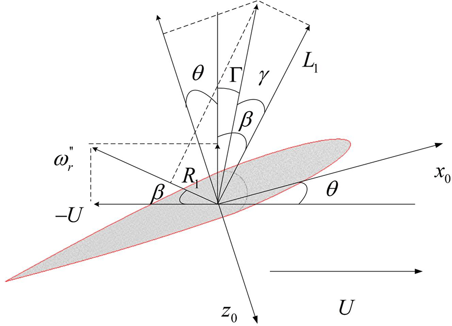
Stress analysis of T-foil.
Lift force and drag are generated when water flows through the T-foil, which is denoted by L
1 and R
1, respectively. The vector relationship is shown in Figure 4. When the trimaran sails in marine, it will inevitably produce pitch motion. Therefore, under normal circumstances, the lift generated by the T-foil is not parallel to the axis. It can be approximated in the actual processing that the lift of the T-foil is parallel to the z axis. In Figure 4, U is the relative velocity between the fluid and the T-foil,


Then, the force component on the z axis can be expressed as

According to CFD and theoretical formula calculations, the lift force of the T-foil is much greater than its drag. It can be known from Figure 4 that the lift arm is larger than the resistance arm. Therefore, the three angles

Similarly, the drag of the flap is ignored, and the lift force of the flap can be written as

The design and installation of appendages are shown in Figure 5. T-foil is installed as front as possible, and the flap is matched well with the trimaran stern streamline. Simultaneously, the stability appendages need to provide enough force to meet the requirement of the trimaran’s vertical motion reduction.

Installation position of the appendages on the trimaran.
Control system
Description of the control system
The wave force and moment mainly produce the motion of the trimaran. The role of the controller is to control the actuator that changes the attack angle of appendages to inhibit the wave force and moment. The actuator includes T-foil, flap, hydraulic system, and so on. The simple control system is shown in Figure 6. The motions of heave and pitch (acceleration, velocity, and displacement) are measured by sensors. The expectation is set as 0 m for heave displacement and 0° for pitch angle. According to the designed controller, the attack angles are changed to suppress the wave force and moment acting on the trimaran.

Control system of the trimaran.
Control logic analysis
The control logic needs to analyze due to the two appendages. The control logic analysis is shown in Figure 7. For the trimaran vertical stabilization controller design, the first step is to identify the correct logic relation between the trimaran motion trend and the actuator’s attack angle tendency. Heave motion is the trimaran centroid upward and downward motion, represented by the red or green arrow in COG. Pitch motion represents the blue or black arrow and includes two conditions: The bow of the trimaran is up while the stern of the trimaran is down, and the bow of the trimaran is down while the stern of the trimaran is up. Under ideal conditions, the appendages require to provide the same direction force when the appendages inhibit the heave motion, and the appendages provide opposite direction force when inhibiting the pitch motion. Figure 7 briefly describes the logic relationship in the ideal state. However, in an actual model test, the trimaran has a certain inertia. The existence of inertia causes the phase of the trimaran has a lagging effect compared to the phase of the waves. Then, the lagging effect must be considered in the controller design.
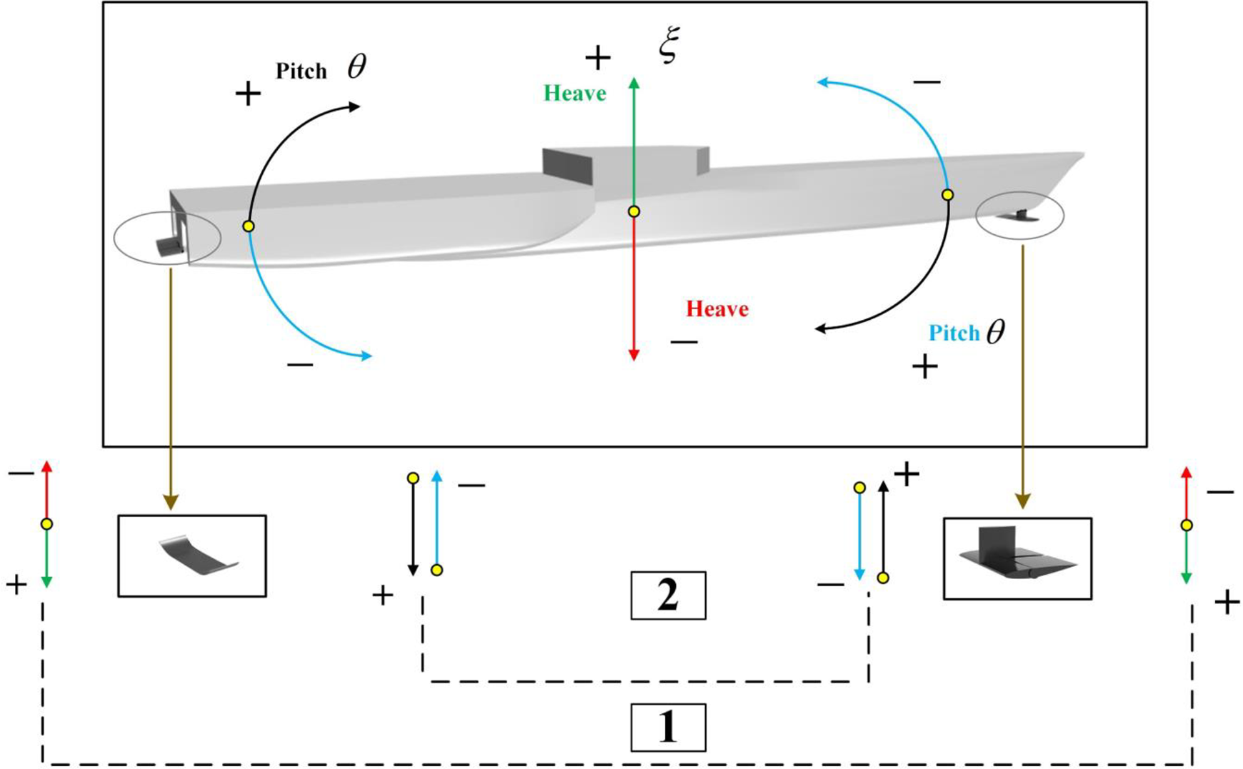
The logic relation of T-foil and flap.
Collaborative control
According to the control logic analysis, the appendages should conduct collaborative control for the trimaran’s vertical motion reduction. The form of the designed controller is shown in Figure 8, which has two independent control channels. The control algorithm of the controller is based on the nonlinear PD controller. In the nonlinear PD controller, the lagging angle mentioned in “Control logic analysis” section is required. The method for obtaining the lagging angle of heave and pitch is as follows: The incoming waves are measured by the wave height gauge, and the phase of the incoming waves is compared with the heave and pitch’s phases of the trimaran. The difference is the lagging angle.

The stability control system of the trimaran.
Model tests and results
Model tests of the trimaran are shown in Figure 9(a) and (b). Using the control algorithm, the results of the trimaran in the different conditions are shown in Figure 10 (the condition of case 2). In the model tests, all cases listed in Table 2 are performed in a towing tank. The results of heave and pitch motions are shown in Figures 11 to 14, and Tables 3 to 6 present the results of model tests.

Model test of the trimaran in towing tank. (a) and (b) The views of bow and aft.

The comparison of trimaran without appendages, with fixed appendages, and active appendages in case 2. (a) The heave comparison, (b) the pitch comparison, and (c, d) the attack angle of T-foil in regular waves controlled.
Comparison of trimaran without appendages, with fixed appendages and active appendages in cases 1–6. (a) Comparison of heave motion and (b) comparison of pitch motion.

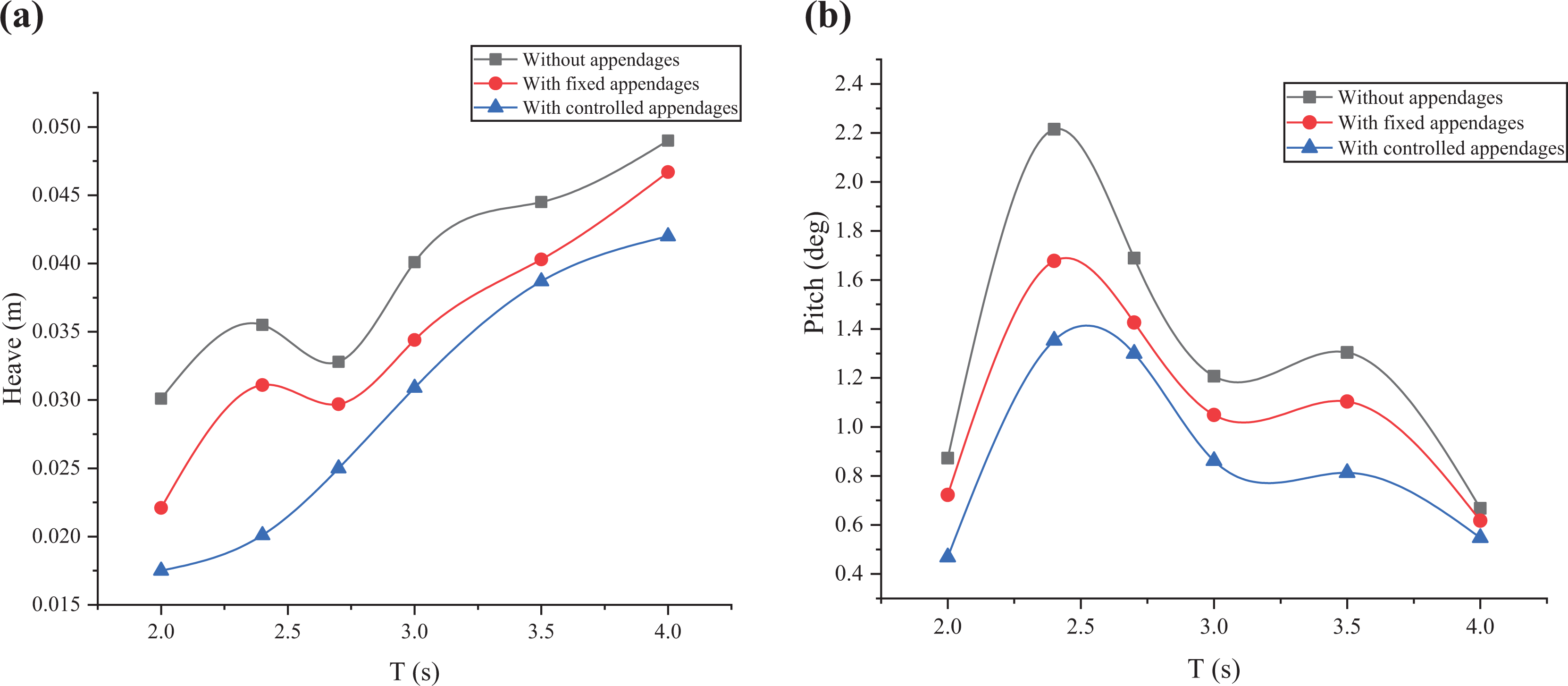
Comparison of trimaran without appendages, with fixed appendages and active appendages in cases 7–12. (a) Comparison of heave motion and (b) comparison of pitch motion.

Comparison of trimaran without appendages, with fixed appendages and active appendages in cases 13–18. (a) Comparison of heave motion and (b) comparison of pitch motion.

Comparison of trimaran without appendages, with fixed appendages and active appendages in cases 19–24. (a) Comparison of heave motion and (b) comparison of pitch motion.
Effectiveness of the heave and pitch motion reduction of the trimaran (cases 1–6).

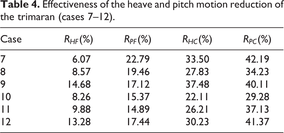
Effectiveness of the heave and pitch motion reduction of the trimaran (cases 7–12).
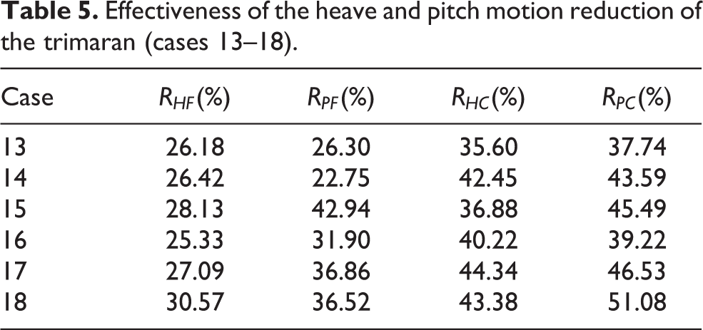
Effectiveness of the heave and pitch motion reduction of the trimaran (cases 13–18).
Effectiveness of the heave and pitch motion reduction of the trimaran (cases 19–24).

Conclusion
This work mainly investigates on heave and pitch motion reduction of a trimaran in regular waves. The appendages, simulation platform, and model tests are introduced and applied in this study. The work can be summarized as follows: The model of the trimaran and appendages is described, including the geometry model and mathematical model. The analysis of the process of the wave to the motion of the trimaran is given, as shown in Figure 3. The analysis of the force and position of the appendages is also shown in Figure 3. At the same time, the analysis of the force of the appendages is shown in Figure 4. A simulation platform has been built and applied in this study. All simulations before the model tests need to rely on this simulation platform. The adjustment of the relevant controller parameters needs to be approximated by simulation. Multiple model tests are conducted to verify the effectiveness of the fixed and controlled appendages. The results shown in Figures 10
to 14 prove that the effect of controlled appendages is better than the fixed appendages.
Footnotes
Declaration of conflicting interests
The author(s) declared no potential conflicts of interest with respect to the research, authorship, and/or publication of this article.
Funding
The author(s) disclosed receipt of the following financial support for the research, authorship, and/or publication of this article: This work was financially supported by the National Natural Science Foundation of China [51379044].