
Abstract
When a segment of a flexible link of a flexible robot is currently sliding through a prismatic joint, it is usually assumed that the elastic deformation of the segment equals to zero. This is a kind of time-dependent boundary condition when formulating the dynamics model of a flexible robot consisting of prismatic joints. Hence, the dynamic modeling and especially the inverse dynamic analysis of the flexible robots with the prismatic joints are challenging. In this article, we present a new development of the dynamic modeling method for a generic two-link flexible robot that consists of a prismatic joint and a revolute joint. Moreover, a new bisection method-based algorithm is proposed to analyze the inverse dynamic responses of the flexible robots. Since the bisection method is a rapid converging method in mathematics, the proposed algorithm is effectively applicable to solving the inverse dynamic problem of a flexible robot in a robust manner. Last, the numerical simulation results show the effectiveness and the robustness of the proposed method.
Introduction
A very important issue in the dynamic modeling and analysis of the flexible robot arm is the computation of joint torques/forces that are required for driving the arm to move along a prescribed trajectory. This is a kind of inverse dynamic problem of manipulators that have been extensively studied for rigid link robots. Different from the inverse dynamics of a rigid link arm, the inverse dynamics of a flexible arm is an order-of-magnitude complex and intricate because of the elastic deformation of the arm links. In particular, the deformation of the arm links, however, is not negligible as the required positioning accuracy of the arm tip increases. Robot arms tracking curved trajectories at a high speed with a large acceleration in a large space, while the tracking error at the arm tip must be kept within an accurate limitation, need to be considered with the elastic deformation of links. If one tries to make such an arm structure sufficiently stiff such that the total elastic deformation is less than the allowed limitation at the arm tip, it could end up with extremely heavy arm mass and inertia. Since drive motors are, in many cases, limited in peak torques, the heavy arm mass and inertia prevent rapid accelerations. A practical solution will not be to design an extremely stiff arm but to allow the arm structure to deform under high accelerations, and compensate for the dynamic deformations by control of dynamic applied torques/forces. Namely, one can estimate the arm tip deformation and compensate for the tip error by computing and modifying the dynamic applied torques/forces acting on joints so that the deflected arm tip may track the trajectory exactly.
Decades ago, the dynamic modeling and analysis of flexible robots have been well documented.
1
–8
There have also been attempts to generalize the kinematic and dynamic modeling problems for the multilink flexible robots, and most of these investigations focus on the multilink flexible robots consisting of all revolute joints.
4,9
–13
There were also studies considering the use of the prismatic joints for the flexible robots.
10,11,14,15
However, these studies mainly focused on the use of the assumed modes method (AMM) for the dynamic modeling. Al-Bedoor and Khulief
14
investigated the dynamics of a sliding flexible link through a prismatic joint. Pan et al.
15
developed the modeling for a two-link flexible robot with a prismatic joint. Korayem et al.
11
addressed the dynamic modeling of a multilink flexible robot, of which each link rotates and reciprocates through a prismatic joint. Khadem and Pirmohammadi
10
formulated the dynamic equations for a multilink flexible robot consisting of the prismatic joints as well. Though there have been several research works working on the dynamic modeling of different kinds of specific flexible robots, little attention has been paid to generalize the finite-element formulation of the dynamic equations for a generalized two links flexible robot that consist of total four specific configurations of kinematic chain. The four configurations include the two revolute joints configuration (
Notice that the flexible robots are the continuous dynamical systems, which are often characterized by an infinite number of degrees of freedom and are governed by the nonlinear coupled differential equations, and the exact solution of such systems is not practical. To formulate the dynamic equations, the continuous dynamical systems are usually discretized using two main methods, including (i) the AMM and (ii) finite-element method (FEM). Theodore and Ghosal 16 and Dwivedy and Eberhard 4 showed that the main drawback of AMM is the difficulty in finding the modes for links with the nonregular cross sections and the multilink robots, and FEM normally requires fewer computations; therefore, FEM lends itself ideally suited for the modeling of multilink flexible robots. The advantages of FEM over AMM have also motivated the finite-element formulation of dynamic equations for the generalized two links flexible robot that is presented in this article.
It can be seen that, in recent years, though there have been several studies related to the flexible manipulators, a few attempts focus on the inverse dynamic analysis for the flexible robots, especially the flexible robots with the translational joints. Most of the works only take into account the revolute joints 17 –28 when considering the dynamic modeling and analysis of a flexible robot. The large deformation of a flexible link was studied by Celentano. 17 The dynamic modeling methods were developed by Li et al. 21 and Wei et al. 22 The vibration of the flexible robots was focused in a number of investigations. 18 –20,23 Also, the control issues were addressed in the recent works. 24 –28
In the literature, the inverse dynamic analysis for flexible robots has been studied by a number of authors. Kwon and Book 29 used AMM for the modeling of the linear inverse dynamics of a single flexible link robot with one rotational joint. Asada et al. 30 employed the coordinates of virtual rigid links to simplify the formulation of the dynamic equations for a flexible robot consisting of two revolute joints. A numerical algorithm was constructed to compute the actuator torques. Bayo et al. 31 and Trautt and Bayo 32 studied the response function of the applied torques imposing on two revolute joints of a flexible robot. The inverse dynamic problem was solved in frequency domain. Boyer and Khalil 33 investigated an AMM formulation incorporated with Newton–Euler approach to derive the dynamic equations. Based on the formulated model, an iterative technique was studied to find out the root of the inverse dynamic equations. Carrera and Serna 34 addressed the inverse dynamics of a flexible robot with all rotary joints. Ledesma and Bayo 35 studied a nonrecursive algorithm for solving the inverse dynamic problem of a flexible robot with revolute joints also. Zhaocai and Yueqing 36 investigated the inverse dynamics of a flexible parallel robot.
It is clearly seen that the inverse dynamics of flexible robots has been investigated; however, most of the investigations use AMM and focus on the robot architecture with all revolute joints. The inverse dynamics of flexible robot with the prismatic joints has been overlooked. Therefore, in this article, we develop the dynamic modeling and analysis of the general flexible manipulator by formulating the dynamic equations with the use of FEM and solving the inverse dynamic problem effectively. A numerical algorithm is proposed to calculate the time-varying values of all joint variables and actuator torques/forces. To construct the algorithm, the effective and robust bisection method is used to find out the feasible solution of the inverse dynamics in time domain. Since no inverse transformation or approximation of the input/output signals is needed for the inversion, the algorithm can be implemented in a simple and effective manner. The numerical simulation results of the inverse dynamics show the effectiveness and the robustness of the proposed method.
In the following, the article is organized with four more sections. The dynamic modeling of the system is detailed in the second section, where the generalized mechanism of the robot is descripted and interpreted. Based on the dynamic model formulated, the inverse dynamic algorithm is proposed in the third section, in which the use of the bisection method is explained. To verify the research results, the numerical simulation is addressed in the fourth section. Conclusions are made in the last section.
Equations of motion
The schematic model of the generalized two-link flexible robot is shown in Figure 1. L
1 and L
2 are the lengths of the links, respectively. m
1 is the mass of link 1, and m
2 is the mass per length unit of link 2. mt
is the mass of a payload at the end point of link 2. The joints J
1 and J
2 are either a prismatic joint

Generalized schematic model of a two-link flexible robot.

Specific models of a two-link flexible robot. (a) CRR model, (b) CRP model, (c) CPR model, and (d) CPP model.
In Figure 1,
Joint displacements and applied force/torque.

Notice that for
As usual, to determine the kinematic relationships for the configurations of the robot, the transformation matrices describing the kinematics of the motion of the joints must be derived. For all the configurations, the homogeneous transformation matrices
Without loss the generality, it is assumed that the first link is rigid. The second link is flexible, which is divided into n beam elements. The elements are assumed interconnected at nodes. Each element j,
For the generalized model, the dynamic equation of motion relies on the Lagrange’s equations with Lagrange function

where T and P are the total kinetic energy and the total potential energy of the system. The vector
The equation of motion can be expressed as

where the structural damping matrix


The notations α and β are the damping ratios of the system (Zhang et al.).
37
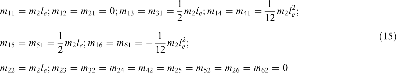
The size of the global mass matrix
Consider an element j of the link 2, a point
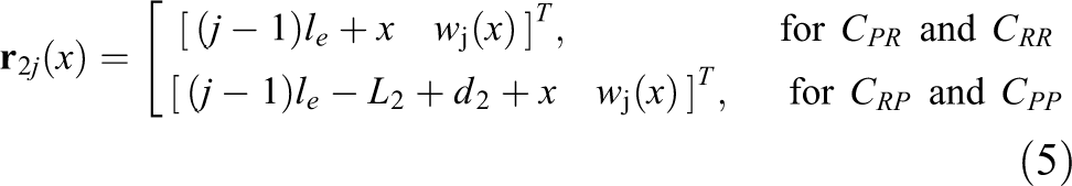
Notice that

where
Therefore, the point

Notice that the end point of the link 2,
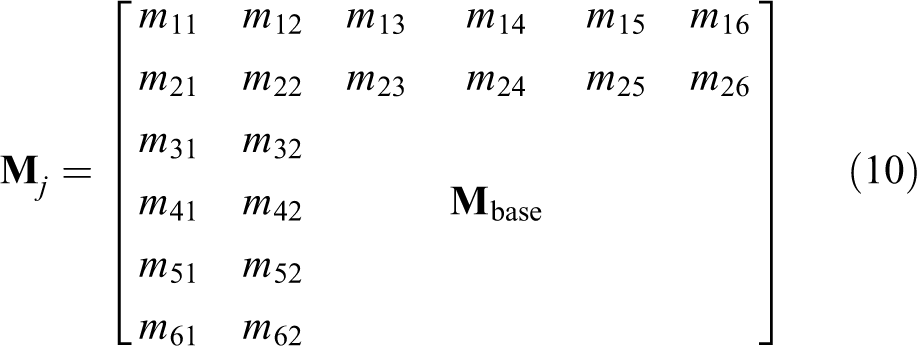
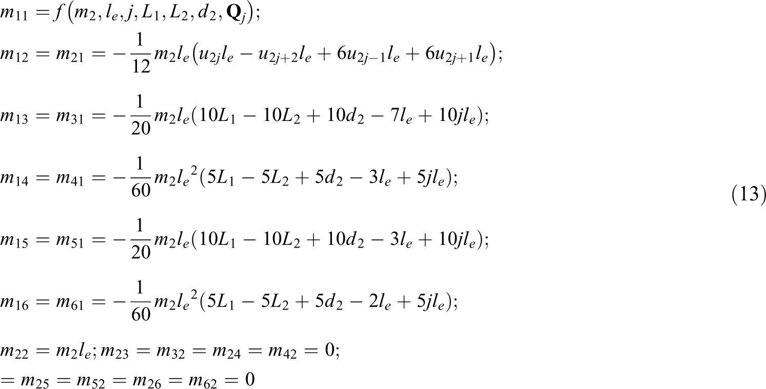
The kinetic energy of the element j of the link 2 is determined as
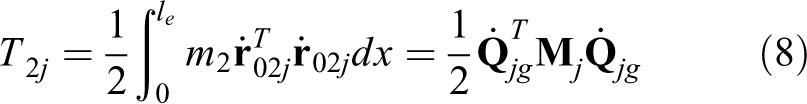
where

Notice that
where

For

For
For

For
The kinetic energy of the link 2 is yielded as

The matrix
The total kinetic energy of the system is determined as

where
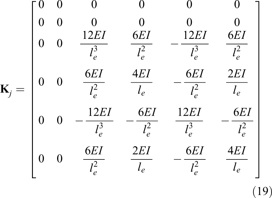
Let us denote E and I as Young’s modulus and the inertial moment of the link 2. The elastic potential energy of the element j,
where the elemental stiffness matrix

The total elastic potential energy of the whole system is yielded as

The global stiffness matrix
Substituting
Boundary conditions
For
Inverse dynamics analysis
The inverse analysis of the flexible robots is a complex problem since there exists
The algorithm is proposed, which is based on the bisection method to compute
At a time
Step 1. Compute the inverse dynamics of the robot without any elastic deformation, based on the inputs
Step 2. Compute the forward dynamics of the flexible model. Based on
Step 3. Compute the trajectory error δ.
The trajectory error δ is approximated as the distance from the point

Step 4. Estimate the interval
Step 5. Modify
Loop the following substeps:
– Compute
– Implement step 2 to recompute
– Set
– Implement step 3 to recompute δ,
– If
Until
Step 6. Finally,
All the values

The bisection algorithm diagram.
Numerical simulations
In this section, a numerical simulation of the inverse dynamics for the two configurations of the robot
Simulation parameters.

The results of the simulation for

Displacement of joints of

The applied force/torque of

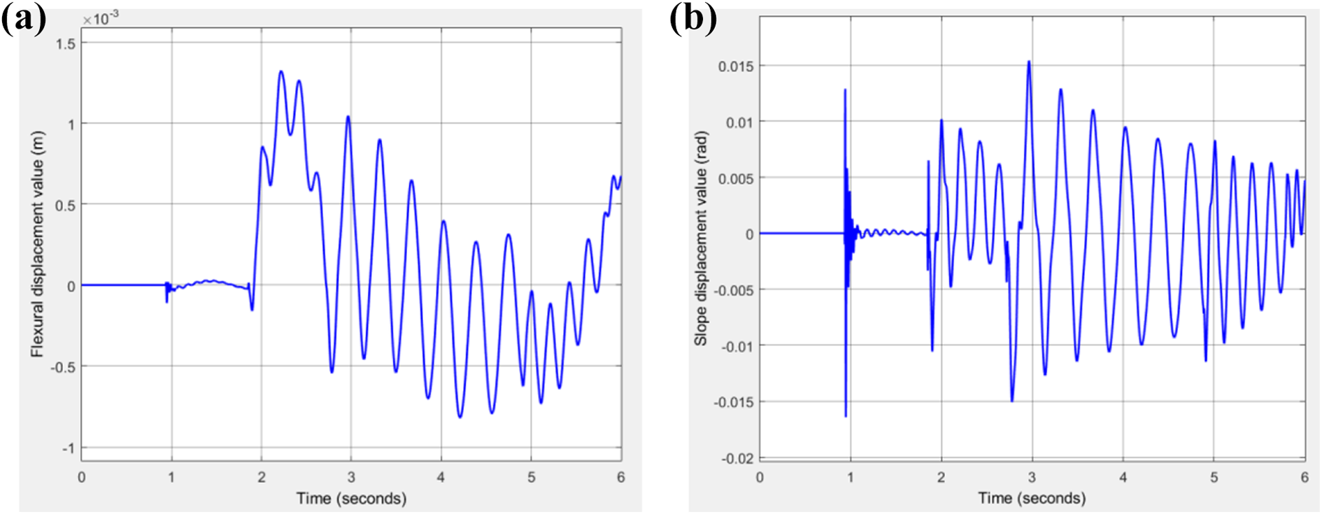
(a) The flexural displacement at the end-effector and (b) slope displacement at the end-effector of
Figure 5 shows the resulting curves
The elastic displacements at the end-effector are shown in Figure 6. The maximum value of the flexural displacement is
The simulation results for the configuration

The displacement of joints of

The applied torque/ force of
(a) The flexural displacement at the end-effector and (b) slope displacement at the end-effector of
Figure 7 shows the value of the joint 1 and joint 2 variables with the difference between the two models does not exceed
Conclusions
A new development of the dynamic modeling and the inverse dynamic analysis for all four configurations of a generalized two-link flexible robot that consists of a prismatic joint and a revolute joint was presented in this study. A recursive finite-element Lagrangian formulation of the dynamic equations for all the configurations of the robot has been addressed. Finally, the numerical simulation results demonstrated the effectiveness and the robustness of the proposed method. In comparison with the previous works, the proposed investigation has two main advantages. The first one is that the dynamic modeling method newly proposed in this article is addressed for a generic two-link flexible robot, which is constructed with different joint types and different joint orders. Hence, the proposed method is generalized and applicable to all four types of two-link flexible robots. The second advantage is that the inverse dynamics of the generic two-link flexible robot is effectively analyzed using a simplified and robust algorithm.
Note that the accuracy and the speed of the bisection algorithm mainly depend on the chosen allowable error ε between the computed trajectory and the desired trajectory. When choosing a small ε, the accuracy of the inverse dynamic responses is increased, however, the computation speed is decreased.
Footnotes
Declaration of conflicting interests
The author(s) declared no potential conflicts of interest with respect to the research, authorship, and/or publication of this article.
Funding
The author(s) disclosed receipt of the following financial support for the research, authorship, and/or publication of this article: This research was supported by Vingroup Innovation Foundation (VINIF) in project code VINIF.2019.DA08.
Appendix
The homogeneous transformation matrices