
Abstract
Tactile information is valuable in determining properties of objects that are inaccessible from visual perception. A new type of tangential friction and normal contact force magnetostrictive tactile sensor was developed based on the inverse magnetostrictive effect, and the force output model has been established. It can measure the exerted force in the range of 0–4 N, and it has a good response to the dynamic force in cycles of 0.25–0.5 s. We present a tactile perception strategy that a manipulator with tactile sensors in its grippers manipulates an object to measure a set of tactile features. It shows that tactile sensing system can use these features and the extreme learning machine algorithm to recognize household objects—purely from tactile sensing—from a small training set. The complex matrixes show the recognition rate is up to 83%.
Introduction
Research in the area of robotic grasping and recognition has turn toward unstructured everyday environments. Vision is an important source of grasping and controlling sensory information, but it is not always enough. 1,2 Tactile sensors can be used to improve grasping performance during grasp execution.
Various types of tactile sensors have been proposed, which can be categorized as piezoresistive, piezoelectric, capacitive, and optical sensors according to the working principle of the transducer. 3 –7 A triaxial tactile sensor with elastic microstructures pressing on piezoresistive cantilevers has been presented in the study by Thanh-Vinh et al. 8 Piezoresistive silicon elements are embedded inside an elastic body because of its fragility in this type of sensor. In the aspect of friction detection, piezoelectric materials are widely used. When a touch and relative motion occur between the sensor and an object, the polyvinylidene fluoride (PVDF) film can induce an electrical field across its boundaries, which is used to measure the contact force and friction. 9 A thick-film piezoelectric friction sensor is described, and the experimental device for simulating sliding is designed and analyzed to allow the friction coefficient between fingertip and contact finger material to be calculated. 10 The sliding friction detection methods have achieved certain results, but there are still some problems. The output of PVDF is a charge signal, very sensitive to temperature changes, about 0.5% degrees per degree Celsius change. Piezoelectric is a good material for friction detection, but it is difficult to distinguish normal force from sliding friction signal.
Magnetostrictive tactile sensor has received attention. Giouroudi et al. 11 have reported that magnetostrictive bilayer sensor system for rotation test has high sensitivity. The characterization of bending magnetostriction in iron–gallium alloys has been investigated for nanowire sensor applications. 12 The magnetostrictive tactile sensor has several advantages compared to other types of tactile sensors, including high precision, simple signal processing circuit, good dynamic performance, and less influence on temperature. 13,14 Here, the magnetostrictive tactile sensors of detecting tangential friction and normal contact force are developed based on the electromagnetic theory, the principle of mechanics, and inverse magnetostrictive effect.
Various approaches have been proposed on tactile information processing 15 –17 but what information can deduce reliably from tactile data and how to use this information to support object recognition have remained unclear. We present four tactile features which can be extracted from tactile sensors, and it describes the deformation properties of objects being manipulated. By taking advantage of the extreme learning machine algorithm and tactile features, the different household object recognition in this system has been realized.
Structure and characteristics of tactile sensor
Structure of magnetostrictive tactile sensor
A magnetostrictive tactile sensor of detecting friction force is mainly composed of Galfenol cantilever beam, solenoid, hard contact rod, copper clamps, silicone shell, and Hall element. Figure 1 is the section view of unstressed state of friction tactile sensor. The Galfenol is a thin plate of polycrystalline Fe83Ga17 with dimensions of 35 × 5 × 1 mm3 and with a [100] texture along the length. Two small cropper cuboids of 5 × 3 × 3 mm3 are placed in a vise and used to clamp one end of the Galfenol plate, resulting in a cantilevered beam. To measure the change in magnetization of the Galfenol, a Hall element is placed behind the cropper clamps and level with the back of the beam. This element is powered with +5 V DC excitation, producing a linear sensing range up to −6 to 6 mT with a sensitivity of 0.42 V/mT. A solenoid with 20 mm length is placed surrounding the Galfenol beam and used to provide DC bias magnetic fields. The silicone shell is used to encapsulate the sensor. The hard contact rod acts as a force transmission element to cause the cantilever to bend. The sensor is a cylindrical with diameter and length of 10 and 40 mm, respectively, and the weight is 12 g. The working principle of the friction sensor is that the hard contact rod receives the external pressure in the vertical direction, which causes the cantilever beam to bend along the z-axis, as shown in Figure 1(b). Because of the inverse magnetostrictive effect, the magnetic induction B of the Galfenol changes, which would further affect the output voltage of the Hall element.
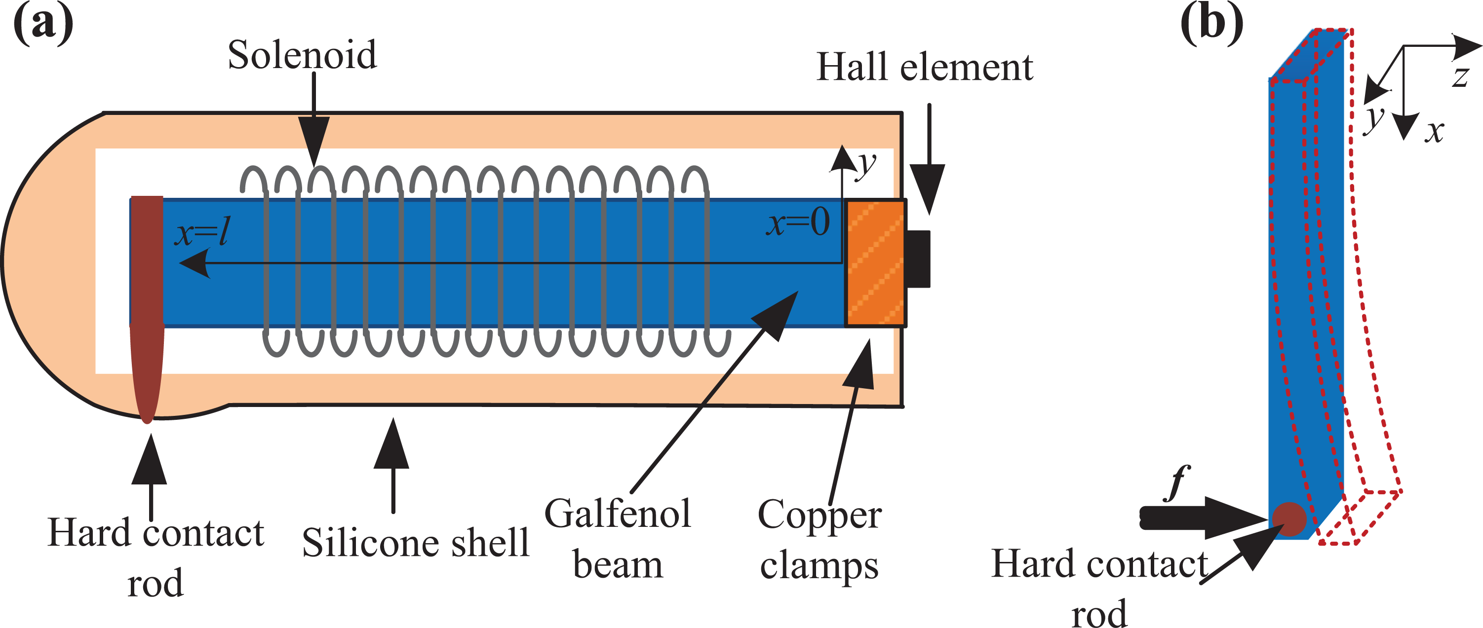
(a) Section view of unstressed state of friction tactile sensor. (b) Bending of Galfenol cantilever beam subjected to friction.
For the magnetostrictive tactile sensor of detecting normal force, the placement of the Galfenol plate becomes vertical and the position of the hard contact rod is in the center of the plate, as shown in Figure 2(a) and (b). The two sensors are mounted on the two grippers of the manipulator, as shown in Figure 2(c).

(a) Structure of tactile sensor for detecting normal force. (b) Structure of tactile sensor for detecting friction force. (c) Magnetostrictive tactile sensors installed on manipulator.
Tactile sensor output model
For friction sensors, the Hall element detects the change of the magnetic induction of the Galfenol cantilever beam. The amplitude of the Hall element measurements is over an order of magnitude lower than the pickup coil, 12 due primarily to measuring the stray field in the small air gap between the back of the beam and the Hall element. But the sensitivity of Hall element is not affected by the frequency of the applied force. The relation between the output voltage and the magnetic induction of the vertical Hall element is

where UH
is the output voltage of the Hall element, KH
is the equivalent Hall parameter, KS
is the magnetic induction transfer coefficient, and
The output signal can be expressed as

where
According to the formula of magnetic induction, the magnetic induction inside Galfenol

where H is an external bias magnetic field strength provided by solenoid, and M is the magnetization.
From the magnetization hysteresis model based on the domain wall theory of ferromagnetic materials, it can be known that is related with the external magnetic field strength H the magnetization M.
18,19
Without considering the hysteresis of the material, the no hysteresis magnetization


where
Equation (5) is carried out by Taylor, ignoring the high-order terms, and according to equations (4) and (6), the magnetization M can be expressed as

The deflection of the cantilever beam is small with a force, and the principal stress is parallel to the neutral axis. The Euler–Bernoulli beam structure dynamics theory is applied. The relationship between the stress σ at the thickness of z and the friction f is

By calculation, it can be obtained
When the pressure is 0, the output voltage is the reference voltage
According to equations (2), (3), (7), and (8), the output voltage of the sensor can be expressed as

Equation (9) describes the relationship between the output voltage and friction on the tactile sensor.
For the normal force sensor, the change of magnetic induction caused by the normal force of the Galfenol plate is consistent with the friction sensor, so the relationship between the normal force F and the output voltage can be obtained, and the expression is in agreement with equation (9).
Theoretical analysis and experimental study
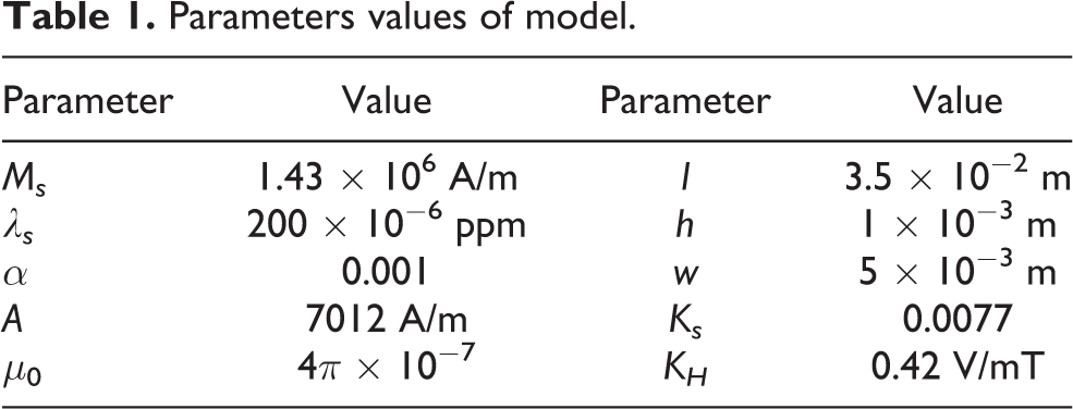
According to Wan et al. 20 and Zhu et al., 21 the parameters of the magnetostrictive material in the tactile sensors output model can be determined, as listed in Table 1.
Parameters values of model.
The experimental test system is set up. It consists of pressurizing device, linear motor, DC power supply, manipulator, PC, data acquisition card, signal generator, and power amplifier. The pressurizing device is used to apply static force. The linear motor is used as a tunable dynamic force source with different vibration periods and amplitudes, applying dynamic signal to the Galfenol plate. The DC power supply provides voltage for the Hall element and the current for the solenoid. The data acquisition card is used to collect the output signal of the Hall element. The manipulator with two grippers is CBT-HD-B2. Each gripper has two degrees of freedom, actuated by a servo motor with an encoder. The manipulator can apply a maximum force of 15 N with the range of 15 and 150 mm.
Figure 3 shows the relationship between the output voltage and friction applied to the sensor, which is calculated by theoretical analysis and measured by experimental test in a bias magnetic field of 4.5 kA/m. The results show that the output voltage of the sensor increases with the increase of friction f. When the friction increases to 4 N, the output voltage reaches 422 mV. The calculating model of the sensor can react to the actual situation in the range of 0–4 N accurately. In the range of 0–2 N, the sensitivity is 125.6 mV/N, and the linearity is 5.98%. In the range of 2–4 N, there is a slight decrease in linearity and sensitivity, the sensitivity is 85.6 mV/N, and the linearity is 4.61%. The test suggests the good performance of the sensor for sensing force. The static output characteristic of the normal force sensor is the same as that of the friction sensor, and it is no longer introduced.
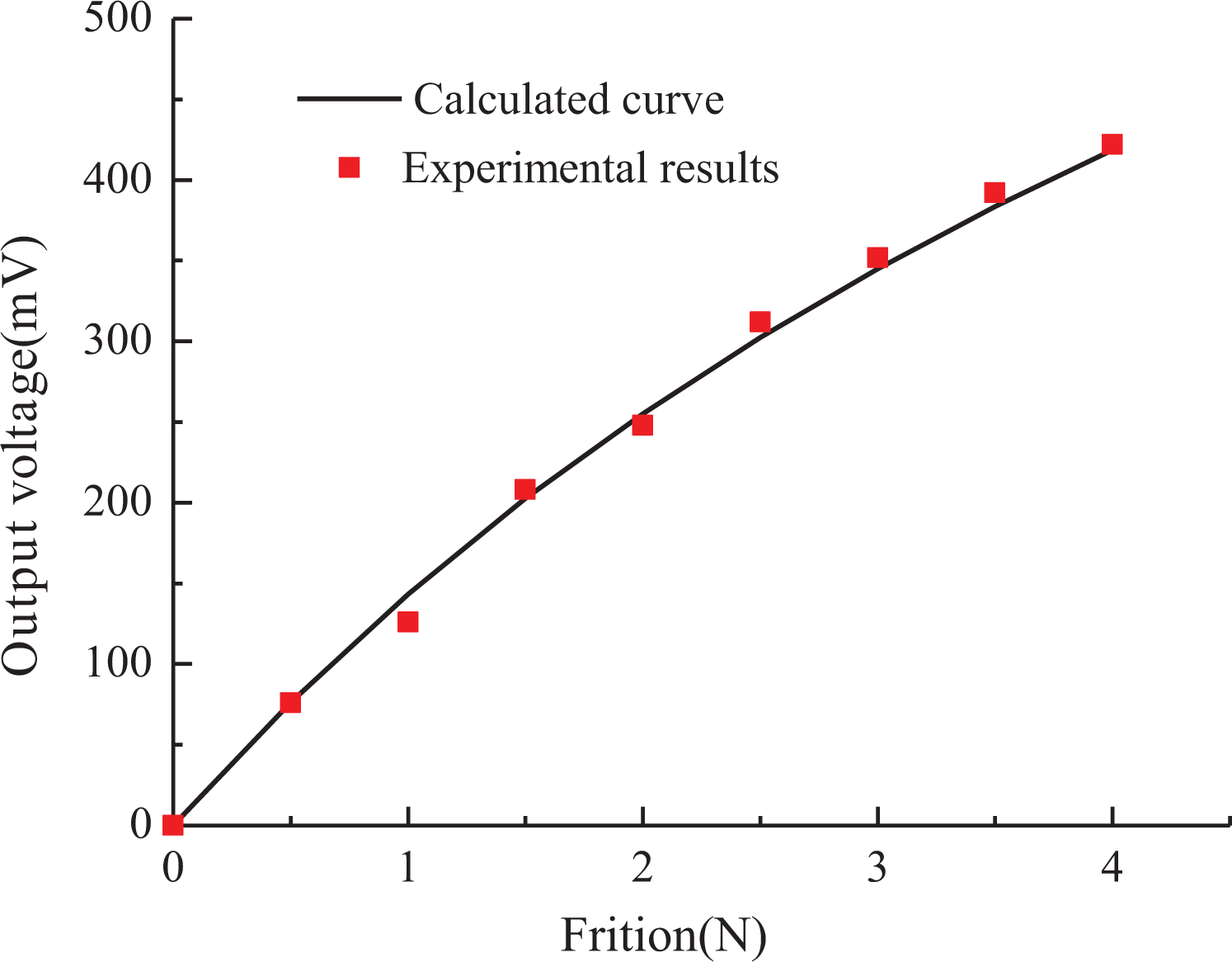
Relationship between the output voltage and the friction in the range of 0–4 N.
To further test the dynamic behavior of the sensor, a linear motor was used as a tunable dynamic force source with different vibration periods and amplitudes. During the test, a quartz dynamic force sensor was fixed on a vibration rod to detect the force dynamically. The voltage was collected ((a) and (b)) and transformed into force expression ((c) and (d)), as shown in Figure 4. The output of quartz dynamic force sensor is the test curve (black line), and the output of magnetostrictive sensor is the measured curve (red line). Under a vibration with a period of 0.5 s, the tactile sensor shows a period of 0.5 s and pressure of nearly 0.8 N (Figure 4(c)). The shape of the dynamic pressure curve collected by the tactile sensor is similar to the original curve, suggesting the good sensing accuracy of the tactile sensor for measuring dynamic pressure. When the period decreases to 0.25 s with pressure up to 1.6 N (Figure 4(d)), the tactile sensor also shows a good accuracy. The tactile frequency of human hand is about 2–4 Hz, demonstrating the tactile sensor is suitable for the grabbing in this range.

Response of the normal force tactile sensor for dynamic force sensing with a period of ((a) and (c)) 0.5 s and ((b) and (d)) 0.25 s.
The test slider is placed between the two grippers of the manipulator, and the grippers are closed to make it stable. Drag the test slider at the speed of 5 mm/s, keeping the moving direction of the slider perpendicular to the two sensor hard contact rods. At the same time, the manipulator is controlled randomly to close and open. (The test slider does not slide on itself during this process.) Figure 5 shows the trends of the output voltage of normal force and friction transducers with time. The output voltage of normal force and friction sensor has the same trend with time, and the output voltage of the friction sensor is proportional to the output voltage of the normal force sensor.

The output voltage of friction and normal force varying with time.
The manipulator is controlled to continue to grip an object. Figure 6 shows the tactile sensor signal and its discrete wavelet transform (DWT) in the course of sliding of grasping object. The detail coefficient of the tangential friction is decomposed by DWT. In 3.4–3.7 s, the slip generates, and the detail coefficient of DWT has an obvious change. The normal force quickly increases at 3.4 s. The grasping force is adjusted dynamically in real time based on the sliding detection.

Sensor signal and its DWT with slipping of grasped object. DWT: discrete wavelet transform.
Feature extraction and object recognition
Our approach to household objects recognition requires measuring a set of features that represent objects properties. Firstly, we will present details of the features and the machine-learning algorithm and then show the experimental results. We assume that the controller could apply a required force profile. The purpose here is that the controller should be able to grasp the object steadily without crushing the objects.
Feature extraction
We assume that the manipulator with grippers reports at each point in time and its position p is sensed by motor encoders. The normal force F and the friction f are measured by tactile sensors. The distance p represents the distance between the two grippers. It decreases until the two grippers contact with the object. The object may deform slightly, but the motion of the grippers will stop finally and the steady state is reached, where the distance between two grippers, the normal force, and the static friction stay constant. Meanwhile, we define two points in time: the time of the gripper first contact with the object, and the time of the sensor values converge to a steady state.
We extract four features, as listed in Table 2.
Features used to recognize an object being grasped.

Extreme learning machine
We have applied extreme learning machine classifier algorithm on our training data in previous works. We have also tried to use other classifiers algorithm, like support vector machines and k-nearest neighbor algorithm, from which we obtained similar results. The advantage of extreme learning machine is that it improves algorithm speed significantly.
Training data
Using the tactile features defined above, we gathered data for 13 kinds of household objects, as shown in Figure 7. The acquisition of training data started with the gripper open fully, and the objects are placed between the grippers. We did not deal with moving the gripper toward the object nor detect the grasping angle via vision. The gripper closed slowly until the steady grabbing is completed. During each trial, we obtained the four features and a label describing the object’s class. Each object is grasped 55 times. As a result, we obtained a training database containing attribute-class tuples. We divided the data set into 11 parts, 10 parts acted as training data and remaining part acted as testing data. Finally, the predictions are compared with the true target class, and the recognition accuracy was computed.

Thirteen kinds of household experimental objects.
Recognition results
Figure 8 shows the confusion matrix for this experiment. The correct recognition will appear on the diagonal, and the error will also be filled in the appropriate square according to the actual recognition class. It is found that the accuracy is 83% in recognizing the 13 household objects. For objects of different shapes, such as empty bottle and cosmetic bottle, the two features p f and p s are quite different, and the two objects are fully recognized. It means that the distance measures using our sensor make sense. For objects of the same shape, such as empty bottle and water bottle, they may have the similar p f and p s, but the F s and f max are different, so they are also recognized. Objects with similar four parameters are sometimes mixed up, like white medicine bottle and black medicine bottle. These results indicate that tactile sensors use the four features to recognize common household objects have a high recognition accuracy rate.

Confusion matrix for recognizing the 13 objects using a manipulator with tactile sensors.
Conclusion
A new type of normal force and friction tactile sensor is designed, and the output characteristic model of the sensors is established. The calculated results are in a good agreement with the experimental data, indicating that the model can describe the output characteristics of the tactile sensor. We tested the dynamic performance of the sensor. The results suggest that the magnetostrictive tactile sensor has a good response to the dynamic force in cycles of 0.25–0.5 s both in period and amplitude. We proposed four features extracted from tactile sensors and proprioception for recognizing the household objects being grasped by a manipulator. The magnetostrictive tactile sensors can provide valuable information for a manipulation robot.
Footnotes
Declaration of conflicting interests
The author(s) declared no potential conflicts of interest with respect to the research, authorship, and/or publication of this article.
Funding
The author(s) disclosed receipt of the following financial support for the research, authorship, and/or publication of this article: This work was supported by the National Natural Science Foundation of China (no. 51777053) and the Natural Science Foundation of Hebei Province (no. E2017202035).