
Abstract
In auto-parking systems, a certain degree of error in the path tracking algorithm is inevitable. This is caused by actuator error, tire slipping, or other factors relevant to and included in the parking process. In such situations, the parking path needs to be updated to finish parking successfully which is referred to as secondary path planning. Herein, a new geometry-based method is proposed to deal with this issue, which can be called the pattern-based method. In this method, a predefined path pattern set consisting of 24 multi-segment patterns is developed first. These patterns are composed of straight lines and arcs and account for constraints due to motion and the immediate environment. Then, a traversal policy is adopted to select the path pattern from the set, and the sequential quadratic programming algorithm is used to determine the optimal parameters that fine-tune the pattern to meet the current constraints. In the simulation section, the effectiveness of the proposed method is demonstrated. Moreover, compared to the search-based method represented by a variation of rapidly exploring random tree*, the proposed method has a higher planning performance.
Keywords
Introduction
Auto-parking system (APS) refers to the technology embedded in the vehicle for autonomous parking. Such a system utilizes sensor technology, computer technology, and automatic control technology to perceive and interpret the environment, plan the parking path, and then track the path. Since APS can not only free the driver from the tedious parking task but also immensely increase safety. It has caught the attention of many manufacturers, including BMW, Audi, Ford, Land Rover, Toyota, Nissan, and Mercedes-Benz. 1 Though APS has made progress in practical applications, the system still faces some challenges before it is completely independent of the driver. For instance, conducting secondary path planning (SPP) still is a big challenge when the vehicle deviates from the preplanned path in the parking process, especially for parallel parking. To this extent, parking path planning in APS requires further study.
Up to now, many methodologies and strategies on the parallel parking planning issue are proposed in the literature, which can be mainly divided into three branches: geometry-based methods, optimization-based methods, and search-based methods. In the geometry-based methods, several kinds of predefined paths consisting of multi-segment fundamental curves, such as straight line, arc, β-spline, and others, are chosen as the parking path patterns, and the curve parameters are employed as the planning variables. These parameters are determined by algebraic or optimization method according to the kinematics and environment constraints. For example, Ankit and Rohan 2 employ the straight line and the circular arc to plan the parking path. Hélène et al. 3 propose a new strategy to find the parallel parking path, in which the parking process is viewed as its inverse process first, retrieving process, and circle arcs are adopted to generate the parking path. Besides the straight line and arc, other curves can also be used to achieve a feasible parking path. For instance, Gomez-Bravo et al. 4 plan the parallel parking path based on β-spline. Liang et al. 5 adopt Bezier curve to smooth the turning point which meets the continuity of the parallel parking requirements. Aneesh et al. 6 take the sigmoidal Gompertz curve as the path component and use an optimization scheme to obtain a parallel parking path. Comparing to the other kinds of methods, the advantage of geometry-based methods mainly lies in the low cost of calculation, while the disadvantage is the poor planning success rate. 7
In the optimization-based method, the motion parameters of the vehicle, like linear velocity and steering angle, are taken as the planning variables. And the variables are obtained under an established optimization framework. For example, a fast optimization-based parking path planner that focuses on narrow environments is developed by Zips et al. 8 Kondak and Hommel 9 formulate parking path planning as a nonlinear optimal control problem and solve it by numerical method. The nonlinear programs are utilized to obtain the time-optimal parking path. 10 –12 Here, a time-optimal parking path is obtained under a unified dynamic optimization framework that includes initial and goal configuration constraints, collision-free constraint, vehicle kinematics constraint, and an optimizing module. The minimum length path is found based on the numerical solution for the Hamilton–Jacobi–Bellman equations, where the fewest possible motion direction changes are required. 13 Comparing to the other kinds of methods, the advantage of the optimization-based methods is the high path quality. But it has a difficulty to express an obstacle as an equation, and the computation cost highly depends on the solver of the optimization problem. 7
In the search-based methods, a collision-free path from the initial configuration to the goal one is conducted by sampling randomly or searching directly. For example, the A* algorithm 14,15 and the rapidly exploring random tree (RRT) 16 –18 are employed to generate parking path. Generally speaking, search-based algorithms are computationally expensive. To reduce the computation cost, the authors of a study at Korea University presented a three-step path planning method for parallel parking and vertical parking. 19 In this method, reachable regions are calculated first based on the collision-free constraint and kinematic constraint. Then the generation of candidate paths follows this by searching through reachable region sets. Finally, an optimal path is achieved by determining the lowest cost according to a cost function. Orientation Aware Space Exploration Guided Heuristic Search is proposed to solve the parallel parking planning problem. 20 It shows constant performance in different maneuvering scenarios and converges faster than basic Exploration Guided Heuristic Search. 21 A two-stage RRT algorithm is presented. 22 In this method, the first step is to create waypoints. Then a feasible path is obtained by constructing a kinematic tree that connects the start and goal waypoints. Besides, RRT* 23 and its variations 24,25 are also effective for parallel parking planning problems. In these methods, the cost of the returned solution converges to the optimum and the computational complexity of this algorithm is within a constant factor of that of their probabilistically complete counterparts. Comparing with the other kinds of methods, the search-based methods can be applied to different planning scenarios, but its computation cost is still too high and the path is not continuous. 26
As mentioned above, most research studies focus on the parallel parking planning problem when the initial configuration is outside the slot. However, few research studies are centered on the SSP problem. In fact, due to the control error and other factors, the vehicle cannot continue to follow the preplanned parking path. In this situation, a new parking path needs to be planned. Nevertheless, since the operation room is highly restricted due to the vehicle being wholly or partially inside the slot, this brings a challenge to plan a new path. For the geometry-based methods, since the design process of predefined paths only considers the scenario when the vehicle is outside of the slot and the amount of them is limited, they cannot solve the SSP problem. For the optimization-based methods and the search-based methods, since the planning process is not limited by the predefined paths, these two kinds of methods have higher success rate and are suitable for solving the SSP problem. However, considering that the general commercial automotive electric control unit (ECU) employed in the assisted parking system 26 –28 has limited performance due to the nature of the price-sensitive automotive industry, it requires that the parking planning algorithm must have low computational complexity. 26 Meanwhile, Lee et al. 26 also pointed out that the search-based methods with high computation cost cannot meet the low planning time requirement. Similarly, the computation cost of the optimization-based method is also too high for automotive ECUs. For example, the computation time of Li’s 11,12 and Micelli’s 13 is beyond 1 s on a PC whose CPU has better computation performance than that of ECU. Thus, we can say that the optimization-based method is also not suitable for the ECU. According to the above analysis, from the viewpoint of computation complexity, the geometry-based method is the most suitable one for automotive ECUs. However, its planning success rate for SPP is too low. Therefore, for the automotive ECU, it is necessary to develop a new parking planning method to solve the SPP issue.
In this article, a new geometry-based method is proposed, which can be called as the pattern-based method. In this method, a pattern set composed of 24 predefined parking path patterns is designed according to the kinematics and environment constraints first. All of the predefined path patterns are multi-segment curves connected by straight lines and arcs. To accelerate the planning process, these predefined patterns are divided into four subsets based on the geometric relationship between the vehicle body and the environment, and the patterns are sorted by the number of path segments in each subset. Then, a traversal searching policy is adopted to select the path pattern from the corresponding pattern subset, and the sequential quadratic programming (SQP) algorithm is used to determine the optimal parameters of that pattern. During optimization, collision-free constraints, kinematics constraints, and goal configuration constraints are all considered. Comparing with the exiting geometry-based methods, since the predefined parking paths of the proposal are designed considering the characteristics of the SPP scenario, the success rate of the proposed method is improved. Meanwhile, by classifying the predefined parking paths and applying an optimization method to determine the parameters of parking paths, the computation cost is much lower than that of the optimization-based and search-based methods. The presented simulation results clearly show that the proposed method has high planning performance.
The rest of this article is organized as follows. In the second section, the kinematics of the vehicle and the parameters of the parallel parking slot are described in detail. The third section presents a unified SPP framework for parallel parking. Simulation studies that cover multiple scenarios to demonstrate the effectiveness of the proposed method are described in the fourth section. Moreover, the performance comparison between the proposed method and the RRT* method is also conducted in this section. Finally, the conclusion is presented in the fifth section.
Problem formulation
The kinematics model of a vehicle
The kinematics model and size parameters, as shown in Figure 1, serve as a basis for the mathematical description of the vehicle.

By ignoring the side slip motion of the vehicle, the kinematics are limited by a nonholonomic constraint that can be written as


Parametric notations of vehicle size and kinematics.
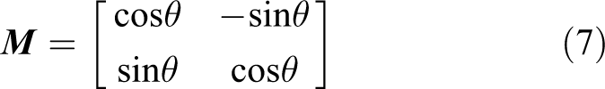
The motion trajectory of the four vertices (A, B, C, and D in Figure 1) in the vehicle body can be obtained according to


where [Px
, Py
]T is the positional coordinates of the rear axle center.
Description of a parallel parking slot
As shown in Figure 2, the notations of a parallel parking slot are as follows: sl and sh denote the slot length and width, respectively. S 1, S 2, S 3, and S 4 are the four corner points of the slot. The inertial coordinate system is established on S 4.

Notations of a parallel parking slot.
Collision-free constraints
Collision-free constraints between the vehicle and obstacles in the environment play an important role in path planning issue. Generally, there are two kinds of collision scenarios: a vertex of the vehicle collides with the edge of the slot (see Figure 3(a)) and an edge of the vehicle collides with one of the two corner points of a slot (see Figure 3(b)). For the first scenario, as shown in Figure 3(a), the environment is at rest. Therefore, to determine a collision, we only need to judge whether the position of any vertex is outside of the allowed area. This is a simple process that requires only a small number of numerical comparisons. For the other type of collision, as shown in Figure 3(b), however, the vehicle is in motion and collision detection is complex.
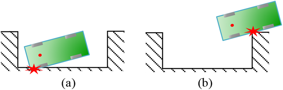
Possible collisions: (a) scenario 1 and (b) scenario 2.
To solve this problem in a straightforward manner, the vehicle body is regarded as a box, and geometry-based methods are used for collision detection. Examples of this include the Minkowski sum method 29 and the area-based method. 10 Here, we employ the area-based method to judge whether a collision occurs, the process of which is as follows.
Setting Q as the vertex of the slot, and the relationship between the vehicle body and Q is depicted in Figure 4. If

Schematic showing a collision decision method: (a) non-collision case and (b) collision case.
Secondary path planning
As presented in the introduction, the APS is required to conduct the SPP when the vehicle deviates the preplanned path. Since the available space is very small due to the vehicle being partly or wholly inside the slot while executing SPP, a continuous path does not exist in most cases. Consequently, it is necessary to design a multi-segment path for the parking operation. By summarizing the human driving experience, we found that drivers can always use a finite number of unique path patterns to park the vehicle to the goal configuration. This inspires us that there may exist a feasible solution set consisting of a finite number of path patterns for the parking path planning issue, and a specific parking path satisfying the constraints can be found out from this set by searching. Based on this idea, a pattern-based parking path planning method is proposed. This method is described in detail below.
Current configuration analysis
The geometric relationship between the vehicle body and the parallel parking slot can be classified into four scenarios which are illustrated in Figure 5, where

Deviation from the preplanned path: (a) y s > y g, θ > 0; (b) y s < y g, θ > 0; (c) y s > y g, θ < 0; and (d) y s < y g, θ < 0.
Path pattern description
Since straight line (S) and circle arc (C) are the basic motions of the vehicle, any path of the vehicle can be decomposed into straight lines and arcs. 30,31 In view of this, we selected the straight line and the arc as the basic units for parking path patterns.
According to the differences in types of the vehicle motion, the basic unit of the parking path can be divided into six types:

Basic path unit:
The following example illustrates the use of patterns in expressing a parking path. As shown in Figure 7, the path is composed of three segments: the first segment denotes the vehicle moving forward, on an arc, with right steer angle φ; the second segment denotes the vehicle moving backward in a straight line; the last segment denotes the vehicle moving forward, again on an arc, but with the left steer angle φ. The entire path can be expressed as

Pattern
Path pattern designing
In terms of the proposed method, the important part is to design a pattern path set. This set is composed of 24 predefined pattern paths. It has been deduced by testing that the planning success rate of the proposed method can be as high as 99% once the maximum number of segments of the predefined path is set to 4. However, the contribution of the added predefined paths to the planning success rate is very little as the maximum number of paths is set to 5. This approach tends to influence the computation time negatively thereby the maximum number is selected as 4 in the current study. The predefined pattern paths whose solution space is small and covered by the other predefined ones are also eliminated to reduce the computation cost. Finally, only 24 predefined pattern paths are left to construct the pattern set. Since some of the valid pattern paths are eliminated, the planning result of the proposed method is not optimal rather local optimal. The removal of valid pattern paths is beneficial since it reduces the computational cost.
According to the description in the “Current configuration analysis” section, the pattern set can be divided into four subsets corresponding to the four scenarios and sorted by the number of segments.
Patterns for scenario 1.
Patterns for scenario 2.

Patterns for scenario 3.

Patterns for scenario 4.
Pattern parameters solving
In the patterns depicted above, all of the values for the segment parameters are unknown, including the length of the straight line, the radius and length of arcs. Herein, the optimization algorithm is employed to determine these parameters. The cost function is the minimum sum distance of the parking path, and the goal configuration constraints, vehicle kinematics constraints, and collision-free constraints are considered. For each pattern, since collision-free constraints are different, the optimization problem is given by a simple unified form in this section first. The specific implementation details are given in Appendix 1. The unified form of the optimization problem is

where li
(
The procedure to plan a feasible parking path is as follows: Obtaining current configuration of the vehicle. Determining the corresponding scenario, shown in Figure 5, of the current configuration. Here, assuming that the ith scenario is selected. Taking the first predefined path of pattern subset i as the candidate path pattern. Solving parameters of the candidate path pattern by the optimization algorithm. If the solution is found, the planning is succeeded and the generated path is returned; otherwise, go to step 6. Judging whether there are pattern paths behind the candidate one. If true, taking the next pattern path as the candidate one and go back to step 4; otherwise, the planning is failed and the driver will take over the vehicle.
Numerical simulation
To illustrate the effectiveness of the proposed method, several numerical simulations with different scenarios are investigated. In these simulations, the geometric size of the adopted vehicle is similar to a mid-sized commercial vehicle, as shown in Table 1. To guarantee safety during parking, there is a margin of d = 0.1 m that is added to the vehicle body size.
Basic parameters of the vehicle.

For the slot dimension, as listed in Table 2, Blackburn 33 presented a specific function to determine the minimum length of the slot corresponding to the car’s size. The function is

where
Basic parameters of the parallel parking slot.

Pattern path effectiveness evaluation
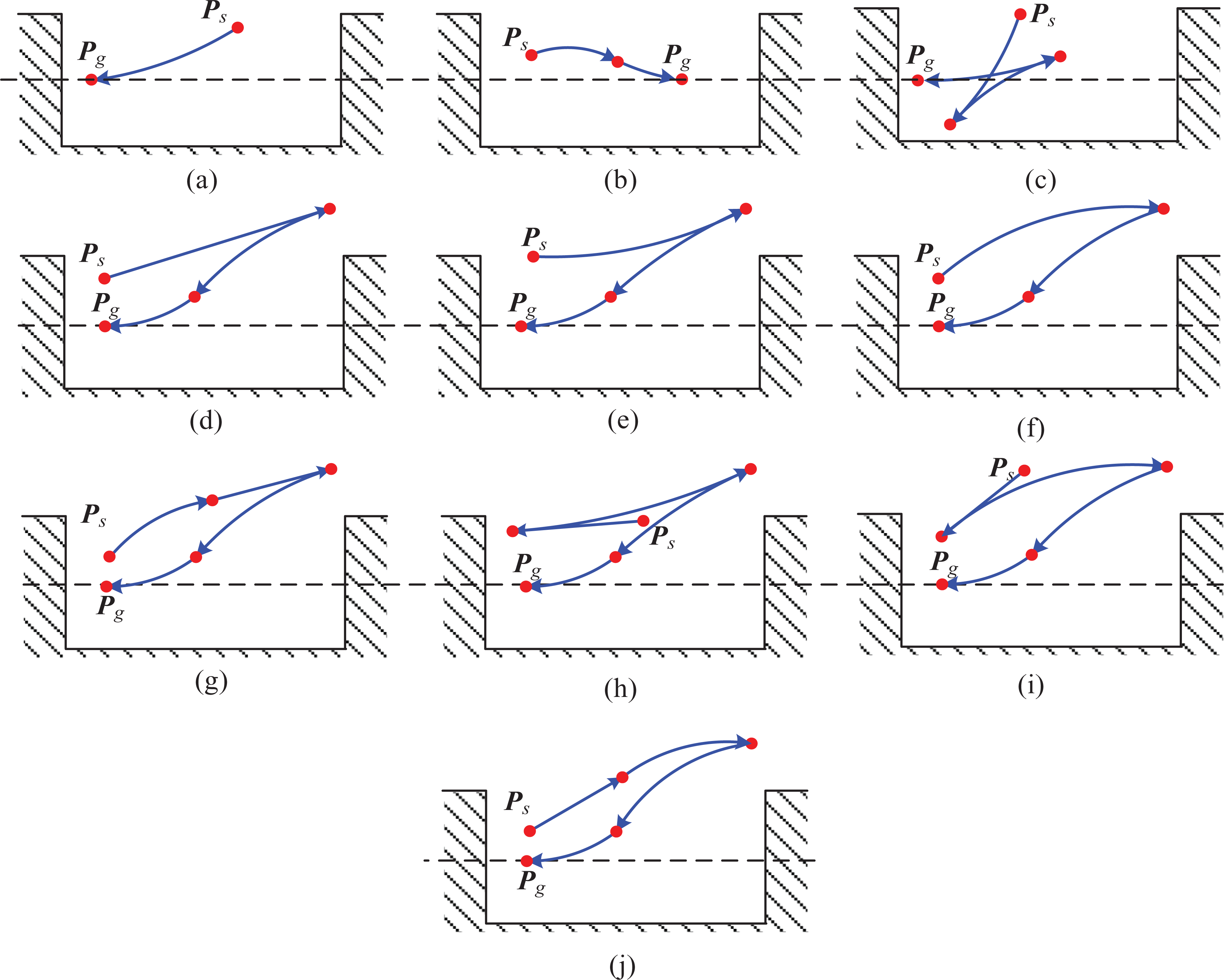
To prove the validity of the predefined path patterns and there is no redundant predefined path, 24 initial configurations, listed in Table 3, are chosen to plan the parking path. These configurations are selected from the corresponding solution space of each pattern, respectively. The slot dimensions are listed in Table 3. The simulations are performed on the Raspberry Pi 3 whose CPU clock speed is 1.2 GHz, RAM is 1 G. The CPU performance of it is similar to the processing unit NXP S32V234 SoC, which is developed for automotive. 34 The parking paths planned by our method are drawn in Figures 12 to 15, and the computing time is listed in Table 4. It can be observed from these figures that every pattern path designed is useful. As could be seen in Table 4, the computing time of the proposed method is less than 220 ms. These illustrate that all of predefined paths are available and the proposed method can be applied in the low-cost platform.
Initial configurations.


Planned path of the pattern-based method in scenario 1: (a) case 1, (b) case 2, (c) case 3, (d) case 4, (e) case5, (f) case 6, (g) case7, (h) case 8, (i) case 9, and (j) case 10.

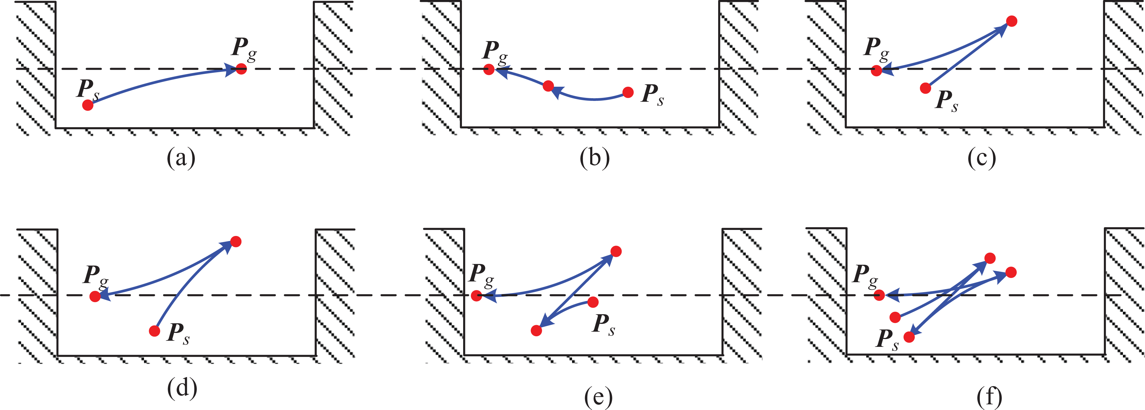
Planned path of the pattern-based method in scenario 2: (a) case 1, (b) case 2, (c) case 3, (d) case 4, (e) case 5, and (f) case 6.

Planned path of the pattern-based method in scenario 3: (a) case 1, (b) case 2, (c) case 3, (d) case 4, and (e) case 5.

Planned path of the pattern-based method in scenario 4: (a) case 1, (b) case 2, and (c) case 3.
Computation time.

Performance analysis
In order to illustrate the validity of the proposed method and analyze its planning performance, the geometry-based method in the work of Hélène et al.,
3
the optimization-based method represented by Li et al.,
12
and RRT* variation
25
are taken as the comparison object. Different from our method, the method in Hélène’s,
3
and RRT* variation, the goal configuration of Li’s method only requires the whole vehicle body inside the parking slot, which means the goal configuration constraints of Li’s is looser than that of the others. In all simulations, the parameters of Li’s are listed in Table 5, all of which are the same as the settings in Li’s. The parameters of RRT* adopted are proved to be optimal by testing, which are listed in Table 6. The simulation in this section is executed on a computer with Intel Core i7-4790 CPU (3.6 GHz) and 16 GB memory. In these simulations, limited time planning success rate and path quality are discussed. The specific simulation scenarios and results are given as follows.
Limited time planning success rate: To evaluate the success rate of the proposed method and illustrate its computation cost is lower than other methods, a group of simulation tests is carried out. In these tests, a uniform sampling manner is employed to select initial configurations from a testing configuration space, as shown in Figure 16. The range of x is (0, sl) (sl = 6.8 m, 7 m, 7.2 m), the range of y is (1 m, 3.4 m), and the range of orientation is (−0.1 rad, π/4 rad). The corresponding sample intervals are 0.1m, 0.1 m, and 0.05 rad, respectively. As a result, three testing configuration sets are obtained. Getting rid of the configurations colliding with the environment, the number of valid samples of them are 11,120, 11,916, and 12,702, respectively. When the maximum computation time is limited to 200 ms, 1000 ms, 5000 ms, 10,000 ms, and 15,000 ms, respectively, the simulation results of the proposed method and the other methods are illustrated in Figure 17. It can be observed that when the maximum computation time is 200 ms, the planning success rates of the proposed method are 99.08%, 99.09%, and 99.13% in three testing scenarios, respectively. Meanwhile, we find that the failed configurations under these time limits, shown in Figure 18, have quite small moving room. Although a feasible parking path can be obtained in these configurations by adding some new patterns consisting of more path segments, it is meaningless. That is because these failed configurations exist only in theory, but the vehicle is scarcely possible to reach. Removing them from the test set, the planning success rate of our method can reach 100%. As could be seen from Figure 17, the success rate of the geometry-based method in Hélène’s
3
is less than 26% no matter what’s the length of the slot and how long the maximum time is. It illustrates that the proposed geometry-based method has a great improvement in the planning success rate compared with the ordinary geometry-based method. Besides, according to Figure 17, the success rate of RRT* variation
25
and Li’s
12
can reach 99% only when the computation time beyond 5000 ms and 15,000 ms, respectively, which demonstrates that these two methods have higher computational complexity than our proposal. Therefore, it can be said that although our method is not complete, it has high success rate and has better limited time planning performance in practice.
Path quality: To compare the proposed method with other methods in terms of path quality including the number of segment and path length, numerical simulations are performed without limiting computation time, respectively. For each scenario listed in Figure 5, three initial configurations are selected randomly to generate paths with the proposed method, Li’s method,
12
and the variation of RRT*,
25
respectively. Considering that the method in Hélèn’s
3
cannot find the parking path in most of initial configurations, it is not selected as the comparison objective in this subsection. For each initial configuration, we performed 10 Monte Carlo simulation runs, respectively. The average path length and average number of segment are listed in Table 7. To show the comparison more clearly, selecting one initial configuration from each scenario and draw its path, as shown in Figure 19.
Parameters of Li’s. 12

Parameter of RRT* variation (MATLAB Automotive Tools).

RRT: rapidly exploring random tree.

Testing area.

Comparison of the pattern-based method and other methods in terms of limited time planning success rate: (a) sl = 6.8 m, (b) sl = 7.0 m, and (c) sl = 7.2 m.

Failed configurations (the red line is the safe margin): (a) sl = 6.8 m, (b) sl = 7 m, and (c) sl = 7.2 m.
Comparison of pattern-based and other methods in terms of path length and number of segment.

RRT: rapidly exploring random tree.

According to Table 7 and Figure 19, the paths generated by RRT* 25 have the longest path length and the biggest number of segments, which is a foreseeable outcome since the RRT* method employs a random sampling way to plan paths. Comparing with the planning results of Li’s method, 12 that of the proposed method has longer path length and similar number of segments. These demonstrate that the quality of the parking path planned by the current approach is higher than RRT* variation, but slightly inefficient than Li’s. The reasons for achieving a shorter path by Li’s are: (i) the goal configuration of Li’s method only requires the vehicle body inside the slot, that is, if the corresponding vehicle body of the initial configuration is almost or completely inside the slot, it only requires to plan either a short parking path or no plan at all. This can explain the reason for the length of the parking paths approaching 0 in scenarios 2 and 4. (ii) Li’s path is generated by optimization in the global solution space, but the path obtained by the proposed method is found by optimization in the local solution space. Thus, it can be said that the result of Li’s is globally optimal, but the result of the current method is locally optimal.
Conclusion
In this article, a new geometry-based parking path planning method, named the pattern-based method, is proposed aimed at solving the SPP when the vehicle deviates from the preplanned path in a parallel parking process. In this method, a predefined path pattern set consisting of 24 path patterns is designed first. Then during planning, a practicable parking path can be found out from the pattern set by searching. In numerical simulations, the effectiveness and the performance of the proposed method are both verified and discussed. Meanwhile, the simulation results demonstrate that the proposed method has high limited time planning success rate compare to geometry-based, optimal-based, and RRT* method and high quality than RRT* method. Although the planning quality of Li’s 12 is better, the computation time is much higher than the method proposed in the current study. Therefore, it can be said that the proposed method has the highest comprehensive performance, and can be considered as a simpler and higher efficient parking path planning method, which is more suitable for automotive ECUs.
Footnotes
Declaration of conflicting interests
The author(s) declared no potential conflicts of interest with respect to the research, authorship, and/or publication of this article.
Funding
The author(s) disclosed receipt of the following financial support for the research, authorship, and/or publication of this article: This work was supported by the Natural Science Foundation of China (grant nos 11772187 and 11802174), the China Postdoctoral Science Foundation (grant no. 2018M632104), and the Shanghai Institute of Technical Physics of the Chinese Academy of Sciences (grant no. CASIR201702).
Appendix 1
According to the “Pattern parameters solving” section, the unified form of optimization equation (8) is
Here, the pattern scenarios 1(d) and 1(h), as shown in Figures 1A and 3A, respectively, are taken as examples to give the implementation details of the optimization problem. (1) In pattern scenario 1(d), as shown in Figure 1A, the length of
The kinematic constraint
The inequality constraint of the goal configuration
The equality constraint of the goal configuration
where x
1, x
2
x
3, l(
(2) In pattern scenario 1(h), as shown in Figure 3A, the length of
The kinematic constraint
The inequality constraint of the goal configuration
The equality constraint of the goal configuration
where x
1, x
2
x
3, x
4
x
5, l(