
Abstract
An impedance control method in null-space for 7-degree-of-freedom redundant manipulators is presented in this article. The null-space impedance motion of the redundant manipulator was described in the angle domain and a null-space impedance equation was established. To successfully obtain joint angular velocity, a high-gain observer is designed. The stability of the proposed control method was proved based on passive theory. The proposed null-space impedance control method not only preserved the Cartesian space impedance characteristics of the redundant manipulator but also achieved null-space impedance control. When the manipulator interacted with the outside world, the position error of the end effector asymptotically converged due to the self-motion of the manipulator. Simulations and experiments of the general impedance control method and the proposed impedance control method verified the effectiveness of the proposed method.
Introduction
With the development of humanoid robots, the control method of redundant manipulators has attracted more and more attention, especially impedance control 1 (e.g. Justin 2 and Robonaut 3 ). Compared to position control, impedance control allows the manipulators to achieve compliance behavior to meet the needs of the manipulators working in a more complex and uncertain environment or even interacting with humans. In the dynamic interaction between the manipulators and the environment, this control method also solves the stability problem caused by repeated switching of force control and position control. Impedance control is one of the most stable methods of controlling the interaction process. 4
Under normal circumstances, it is difficult to achieve interactions between the manipulators and the environment or humans using the position control strategy. Therefore, the design of the control strategy for the contact force between the manipulators and the environment has become one of the most important research areas in robotics. The force control method can be divided into hybrid position/force control 5,6 and impedance control. 7 –9 The most significant disadvantage of hybrid position/force control is that the importance of mechanical impedance is not considered. Hogan 7 proposed the basic theory of impedance control and showed that vector control such as position and force is not enough to control the dynamic contact force between the manipulators and the environment, whereas an impedance control strategy can overcome this problem. The impedance control strategy ignores the difference between the position control and the force control subspace. It does not attempt to track a specific position trajectory or force trajectory. Instead, it maintains a mechanical impedance relationship between the position error of the manipulators and the contact force so that the manipulators exhibit compliant characteristics to operate in complex and uncertain environments or even interact with humans.
The control of redundant manipulators has not yet reached the level of maturity of non-redundant manipulators but some studies have been conducted to address force control issues in redundant manipulator control strategies. Hsu et al. 10 first proposed a control method using redundancy but the method did not provide a unique relationship between the Cartesian space and joint space. Gertz et al., 11 Walker, 12 and Lin et al. 13 used the inertia-weighted generalized inverse of the Jacobian to solve for redundancy to reduce the impact force. However, these solutions are single-objective optimization algorithms and cannot be used to satisfy additional conditions. The augmented impedance control method is discussed in detail in the literature. 14,15 These schemes can be considered multi-objective optimization algorithms because they can be incorporated into different additional tasks without modifying the control strategy and control rate. On this basis, multi-priority impedance control has been extensively studied.
Sentis and Khatib 16 proposed a multi-priority impedance control framework. Based on this framework, Albu-Schaffer and Hirzinger 17 divided the end effector and joint impedance into two priorities. Platt et al. 18 summarized the control methods using this framework, which enabled them to implement arbitrary optimization indicators. In fact, this framework defines different priority levels in Cartesian space and joint space. When the Cartesian space impedance is satisfied, the joint impedance is achieved but the null-space motion of the arm is not considered. In the absence of a null-space description, the joint impedance is coupled to the Cartesian space impedance, that is, the external force acting on the arm causes unintended Cartesian space motion. Sadeghian et al. 19 proposed a nonlinear control algorithm to achieve proper impedance behavior in null-space but ignored the Cartesian space position error. Although Ott et al. 20 used the Lyapunov function to prove the integrability of null-space velocity, most of the methods in those documents extend the redundant solution from the velocity domain to the acceleration domain.
In recent years, some experimental results of force or compliance control of redundant manipulator systems have been published. The solution proposed in Nemec and Zlajpah 21 decoupled the motion of the manipulator into the motion of the task space and the motion of the internal space; this scheme was implemented on a 4-degree-of-freedom (DOF) redundant manipulator. Hattori and Ohnishi 22 proposed a distributed compliant motion control scheme for redundant manipulators based on the concept of virtual impedance. The robotic arm was divided into subsystems and each subsystem used a virtual impedance and information from the end effector to operate autonomously; simulation and experimental results of the scheme were obtained for the planar redundant manipulator. An extended impedance control strategy based on a weighted inner product in joint space was provided in Oh et al. 23 and experiments were carried out on a 3-link planar manipulator. In Oh and Chung, 24 a robust motion tracking controller based on a momentum feedback disturbance observer was designed for redundant manipulators. The observer used state-space planning to deal with model uncertainty and external disturbances. The performance of the controller was tested using a relatively simple 3-DOF planar manipulator. In Assal et al., 25 a neural network-based inverse kinematics control strategy was designed for redundant manipulators; this strategy had the additional task of avoiding joint limits and although the controller performed well, the dynamics of the manipulator were completely ignored and, therefore, this solution is not suitable for force control. In Zergeroglu et al., 26 the author began with the Lyapunov design idea and designed a nonlinear controller for a redundant manipulator based on the feedback linearization theory. This control strategy did not require accurate inverse kinematic calculations and did not limit the self-motion of the manipulator; therefore, an additional DOF could be used to accomplish various subtasks. However, this controller was only tested on the position subspace of a simple 3-DOF planar robot. An extended operating space solution was provided in Park et al. 27 ; a manipulator with redundancy was analyzed and controlled based on this scheme. Seraji and Steele 28 designed a nonlinear contact force controller that included a nonlinear gain section in series with a linear fixed gain proportional–integral force controller and a proportional–derivative compliance controller. The program was tested on a 7-DOF manipulator platform. Experimental studies on the contact force control of a 7-DOF manipulator are also discussed in Seraji and Steele. 29 The study by Albu-Schaffer et al. 30 investigated the impedance control scheme based on a singular perturbation and recent research result included the position, torque, and impedance control for the flexible joint manipulator proposed by Albu-Schaffer et al. 31 The abovementioned scheme based on the passive theory was tested on a 7-DOF manipulator developed by the German Aerospace Center (DLR).
In general, the main objective of impedance control is to control the position and contact force of the end effector of the manipulator in Cartesian space and to satisfy a linear relationship between the position error and the force error. For example, Caccavale et al. 32 proposed a 6-DOF simplified impedance method that corresponds geometrically to Cartesian space operations tasks. However, for redundant robots, one additional task is to control their null-space motion (i.e. self-motion). The null-space motion of the manipulator resulting from the reasonable redundant joint motion does not affect the movement of the end of the manipulator, making the redundant manipulator more flexible than the non-redundant manipulator.
Therefore, the objective of this study is to achieve null-space motion control, that is, null-space impedance associated with the contact force acting on the manipulator. When the redundant manipulator performs an operation, it collides with humans. This collision can result in position errors at the end of the manipulator when using traditional impedance control. In this article, we describe the null-space motion of the 7-DOF redundant manipulator from a new perspective. Based on the characteristics of this self-motion, null-space impedance control of 7-DOF redundant manipulators is proposed. The method ensures that the manipulator exhibits compliant behavior by performing null-space motion when it is impacted and does not affect the position of the end effector.
This article is organized as follows. In the second section, the inner loop position impedance control is introduced. In the third section, the null-space impedance control method is proposed. First, the arm plane and the compliant plane are introduced to describe the null-space motion of the redundant manipulator. Next, a null-space impedance equation is established based on the energy theory to achieve improved impedance control based on the arm angles. In the fourth section, the singularity and stability of the proposed method are analyzed. The simulations and experimental evaluations of the 7-DOF redundant manipulator are described in the fifth section. The conclusions are drawn in the sixth section.
Inner loop position impedance control
Consider a manipulator with n-DOF; the general dynamic equations including the contact with the environment have been defined in Peters et al. 33

where
To simplify the equation, the following expression is introduced

where η is defined as following

Therefore, equation (1) can be re-written by using an implicit feed-forward term

Normally, in the actual operation of the manipulator, the end effector motion occurs in the operating space. Therefore, it is more practical to use a controller for the operating space than the joint space. In the m-dimensional operating space, the Cartesian pose x of the end effector can be described as an m-dimensional vector about its axis; therefore, the Cartesian velocity and Cartesian acceleration can be obtained. The relationship between the n-DOF manipulator and its m-dimensional operating space can be expressed as
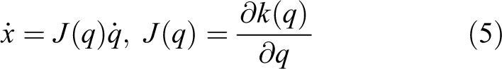

where
For redundant manipulators,

where
Impedance control makes the end effector exhibit linear impedance in Cartesian space. 34 Its goal is to control the stiffness, damping, and inertia of the end effector as follows

where
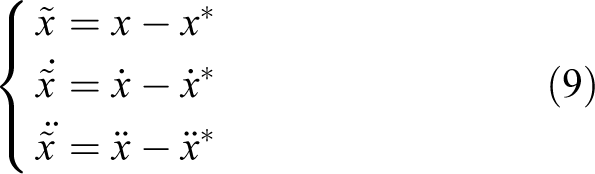
where
Combined with equation (6) and using

where
Substituting equation (10) into equation (4) yields

Using the force Jacobian relationship

It is worth noting that the basic control strategy of using the inner loop position combined with the gravity and friction compensation controller of the manipulator is consistent with the general concept of industrial robot control. Since it is difficult to obtain relatively accurate manipulator model parameters, it may not be necessary to model the manipulator system and design a complex control algorithm based on the model. The computational cost of increasing the computational speed for calculating the model parameters of the manipulator are also large, especially in the absence of a priori knowledge of the exact parameter values, and the control law that relies entirely on the model will be meaningless. A large number of practical applications in industrial robots have shown that the error-driven control law combined with an appropriate compensation control strategy can ensure tracking accuracy and control performance and the algorithm also simplifies the implementation of the complete control scheme on the experimental platform.
Considering the general joint sensor, only the joint angle value at each moment can be obtained. To achieve inner loop position control, the joint angular velocity is also needed. When the manipulator is in low-speed motion, the joint angular velocity calculated from the joint angle difference usually contains noise. Using this value directly will weaken the control accuracy of the manipulator and may even cause instability of the control system. In addition, the digital filtering method causes a large delay in the control system. The high-gain observer is widely used due to its good robustness. The observer successfully suppresses the influence of disturbances while observing the unknown state quantity. In addition, since the high-gain observer 35 can estimate the derivative of the system output based on the output of the system, the estimation process does not depend on the mathematical model of the system. Therefore, the high-gain observer estimates the joint angle and obtains the observed joint angular velocity.
The basic equation of a high-gain observer is

where ei
is needed to estimate system status signals;
To eliminate peaking phenomenon in high-gain observers, defined as follows

where
Substituting equation (14) into equation (13), the joint angular velocity equation based on the high-gain observer is

Solving the equation (15) gives the observation speed as

In summary, the redundant manipulator inner loop position impedance control method results in a mass-damping-spring (M-D-S) system, which is equivalent to arbitrary end effector impedance control in equation (8). However, for a 7-DOF redundant manipulator (n = 7 and m = 6, namely, the redundant DOF is one), this control method lacks a complete description of the null-space motion impedance. Moreover, although the value of the input term λ does not affect the Cartesian space motion of the end effector, it is necessary to consider how to optimize the variable λ to achieve effective use of the null-space motion (i.e. self-motion) of the manipulator itself.
Null-space impedance control
In Cartesian space, the impedance of the end effector is defined by a second-order linear equation. However, as mentioned in the second section, this definition does not ensure that the null-space has the same impedance characteristics as the Cartesian space. This section will present an impedance control method whose goal is to: Describe the null-space motion of the redundant manipulator in the angle domain. Ensure that the manipulator itself is an M-D-S system. Preserve the Cartesian space impedance while achieving null-space impedance.
Null-space motion expression
The 7-DOF redundant manipulator is equivalent to a spherical shoulder joint, a rotating elbow joint, and a spherical wrist joint (S-R-S) connected in sequence; a simplified model is shown in Figure 1. To analyze the redundant DOF in Cartesian space, Kreutz-Delgado et al. proposed a self-motion-based parameter “arm angle,” which is the dihedral angle between the arm plane and the reference plane. The arm plane is defined by three points, namely, the shoulder joint, the elbow joint, and the wrist joint. 36 Since the arm angle is equivalent to the redundant DOF of the manipulator in the Cartesian space, the arm angle can be arbitrarily selected regardless of the position of the end effector. However, in the original definition, the reference plane is determined by a fixed vector. In this section, a compliant plane is used and the arm angle is redefined as the angle between the compliant plane and the arm plane. If the arm angle is determined, the compliant plane is also uniquely determined.

The manipulator model of the proposed impedance control scheme.
Let
The axis vector

where

where dse and dew are the lengths of the upper and lower arms, respectively.
It should be noted that
Thus, any self-motion of the S-R-S manipulator for a fixed tip pose does not change the wrist position, while the wrist orientation viewed from the base does vary depending on the rotation angle around the shoulder-wrist axis. The orientational change resulting from the rotation by the arm angle

where
As a result, the wrist orientation viewed from the base coordinate system is described by

where
Since the movement of the manipulator from the desired arm plane to the compliant plane has null-space motion, the null-space position

where
Null-space impedance equation
The null-space impedance equation can be derived relatively easily using the energy term. First, we consider the kinetic energy TN , which is defined as

where MN
is a positive inertia scalar and
It should be noted that TN contains relative velocity, which is physically expressed as pseudo-kinetic energy; it holds actual physical meaning only when the arm plane is expected to be stationary.
Then, the potential energy can be expressed as follows

where KN
is a positive stiffness scalar. α is a positive constant that is determined by
The derivatives of equations (22) and (23) are as follows


where


where
Then, the damping force fD is expressed as

where DN is a positive damping scalar.
Finally, by integrating equations (26), (27), and (28), the null-space impedance equation is obtained

where fN
is the force applied to the manipulator and


Impedance control based on the arm angle
The null-space impedance equation defined by equation (29) can be simplified to

where

where

To further simplify the equation, the following expression is introduced
Thus, the desired angular acceleration can be rewritten as

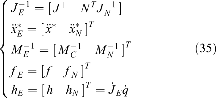
Therefore, the joint angular acceleration can be re-expressed by the Cartesian space and null-space variables. Equation (36) is substituted into equation (4) to obtain

Using the force Jacobian relationship

It should be pointed out that equation (38) is similar to equation (12). The reason is that due to the use of the null-space impedance, the equation extends the general expression of Cartesian space.
Singularity and stability analysis
Singularity
The Jacobian matrix defines the mapping between the joint velocity and the Cartesian line/angular velocity. The most common problem in calculating the Jacobian is the kinematic singularity, namely, the rank of the Jacobian matrix is not full. Near the singular point, even a small Cartesian speed can generate very large joint speeds. For a 7-DOF redundant manipulator, the singularity can be divided into boundary singularity and internal singularity. The boundary singularity occurs only when the manipulator reaches the edge of the operating space; this problem can easily be solved by conditionally limiting the unfolding or retracting of the manipulator. However, internal singularities appear inside the operating space, which has a significant effect on the operation. Therefore, the Jacobian matrix JN must be designed to ensure that JE is non-singular.
The choice of JN
is based on the weight matrix of positive definite symmetry

The matrix N can be solved by the method described in Huang and Varma 37 and Chen and Walker 38 Clearly, JE obtained by JN has full rank, namely, it is non-singular and its inverse can be calculated using equation (35), where

Stability
Consider system (36) and control law (38). The stability of the system is proved in detail based on passive theory and Lyapunov function can be found in Appendix 1.
Control simulation and experiment
Manipulator modeling in SimMechanics
SimMechanics was used to develop the manipulator system model. The main steps are as follows:
The manipulator parameters provided by the CAD model are used and to configure the inertia, the number of DOF and the constraint relationship of the SimMechanics module are determined, as shown in Table 1.
Set the sensor, which records the motion and force of the manipulator, the actuator and the initial motion state, as shown in Figure 2(a).
Import the CAD model as an external graphics file that defines the geometry of the manipulator, as shown in Figure 2(b).
Start the simulation and call the appropriate Simulink solver.
Link parameters of a 7-DOF manipulator model.

DOF: degree-of-freedom.

SimMechanics block diagram of a 7-DOF manipulator model. (a) Block diagram and (b) visualize model. DOF: degree-of-freedom.
7-DOF redundant manipulator null-space impedance control simulation
The proposed null-space impedance control of the redundant manipulators is validated by the aforementioned 7-DOF redundant manipulator model. To map the motion of the joint to a mathematical manifold with motion constraints and to obtain the force, the Simulink ode3 fixed-step solver was used with the 1 ms step. The symbolic calculations for the other kinematics and dynamics were performed in Maple. In the simulation, the influences of the joint flexibility and dissipation are neglected and the contact force of the environment on the manipulator is divided into two parts, namely

where
To evaluate the dynamic response characteristics of the traditional control (12) and the proposed control (38), a 15-N step force is applied to the elbow joint along the y-axis of the base coordinate system and the end of the manipulator, respectively. The initial position of the end of the manipulator is
The first objective of the simulation is to verify the performance of the Cartesian space impedance of the manipulator under a 15-N step force. The simulation result is shown in Figure 3. When the control equation (38) is used, the end of the manipulator moves 20 mm in the y-axis direction of the base coordinate system under the force but there are no significant displacements in the x and z-axes directions. The same result was observed when equation (12) was used. The two control laws cause the manipulator to exhibit the same Cartesian space impedance characteristic, indicating that there is no difference in the Cartesian space impedance performance between the use of equation (38) and equation (12).

Position error response to the force on the end effector. (a) General impedance control and (b) null-space impedance control.
The second objective of the simulation is to verify the performance of the null-space impedance of the manipulator under a 15-N step force. The simulation result is shown in Figure 4.

Position error response to the force on the elbow. (a) General impedance control and (b) null-space impedance control.
When equation (12) is used and the force is applied to the elbow, the end position of the manipulator moves 13 mm in the x-axis direction, 17 mm in the y-axis direction, and 9 mm in the z-axis direction. When equation (38) is used, the end position of the manipulator moves 1 mm in the x-axis direction, 6 mm in the y-axis direction, and 3 mm in the z-axis direction. Ultimately, the errors converge to zero. This shows that when an external force acts on the manipulator, the end position error of the manipulator accumulates when equation (12) is used. This is due to the fact that the compliant motion of the joint of the manipulator is nonlinearly mapped to its irregular motion of the end effector by kinematics. In contrast, the controller (38) keeps the end position error of the manipulator in a certain range and the error eventually converges to zero. Unlike in the general impedance method, the arm angle changes in the null-space impedance method.
To investigate the influence of the null-space impedance parameters on the change in the arm angle, four groups of null-space impedance parameters were selected for the simulation, as shown in Table 2. The simulation result is shown in Figure 5.
Four groups of null-space impedance parameters.


The simulation results for the different null-space impedance parameters. (a) Position error, (b) arm angle misalignment, (c) arm angle velocity, and (d) arm angle acceleration.
It can be seen from the simulation result that the end position error of the manipulator converged and null-space impedance control was achieved for all four group parameters; however, the different impedance parameters affected the steady-state angle, stabilization time, dynamic angular velocity, and angular acceleration of the arm angle.
For the group a parameters, the maximum position error of the end of the manipulator is 6 mm, the steady-state arm angle is 20°, the settling time is 6 s, the maximum instantaneous angular velocity is 13°/s, and the maximum instantaneous angular acceleration is 100°/s2.
For the group b parameters, the maximum position error of the end of the manipulator is 10 mm, the steady-state arm angle is 20°, the settling time is 6 s, the maximum instantaneous angular velocity is 15°/s, and the maximum instantaneous angular acceleration is 500°/s2.
For the group c parameters, the maximum position error of the end of the manipulator is 8 mm, the steady-state arm angle is 20°, the settling time is 5 s, the maximum instantaneous angular velocity is 21°/s, and the maximum instantaneous angular acceleration is 100°/s2.
For the group d parameters, the maximum position error of the end of the manipulator is 6 mm, the steady-state arm angle is 10°, the settling time is 6 s, the maximum instantaneous angular velocity is 12°/s, and the maximum instantaneous angular acceleration is 100°/s2.
The simulation results indicate that under the same external force, the parameter KN affects the steady-state arm angle; the larger KN is, the smaller the steady-state arm angle is. The parameter DN affects the angular velocity and the stabilization time of the arm angle; the larger DN is, the smaller the angular velocity and the longer the stabilization time are. The parameter MN affects the angular acceleration and acceleration time of the arm angle. The smaller MN is, the larger the angular acceleration and the shorter the acceleration time are. It is worth noting that when the parameter DN is small, a certain overshoot occurs in the arm angle. In addition, when the parameter MN is small, the change in the arm angle is greater. These parameters need to be carefully adjusted in the application.
Dual 7-DOF redundant manipulator null-space impedance control experiment
The purpose of the dual manipulator null-space impedance control experiment is to verify the dynamic response characteristics of the null-space when humans interact with the manipulator.
In this experiment, the object is held by dual manipulators, and the object is positioned at the (300, 0, −550) mm from the base of the right manipulators. Interaction with the manipulators is then implemented, that is, the force is applied to the elbow of the manipulators and the object is required to remain stationary. The position error is less than 5 mm, as shown in Figure 6.

Experimental results of (a) general impedance control and (b) null-space impedance control.
For comparison purposes, two kinds of impedance control methods were compared in the experiment, that is, general impedance control, which does not consider the null-space of the redundant manipulator and the proposed null-space impedance control of the redundant manipulator. When the general impedance control method is used (Figure 6(a)), due to the compliant nature of the manipulator, the entire manipulator swings with the external force, resulting in an irregular change in the position of the object; the position error accumulates and the maximum position error is 35 mm, as shown in Figure 7.
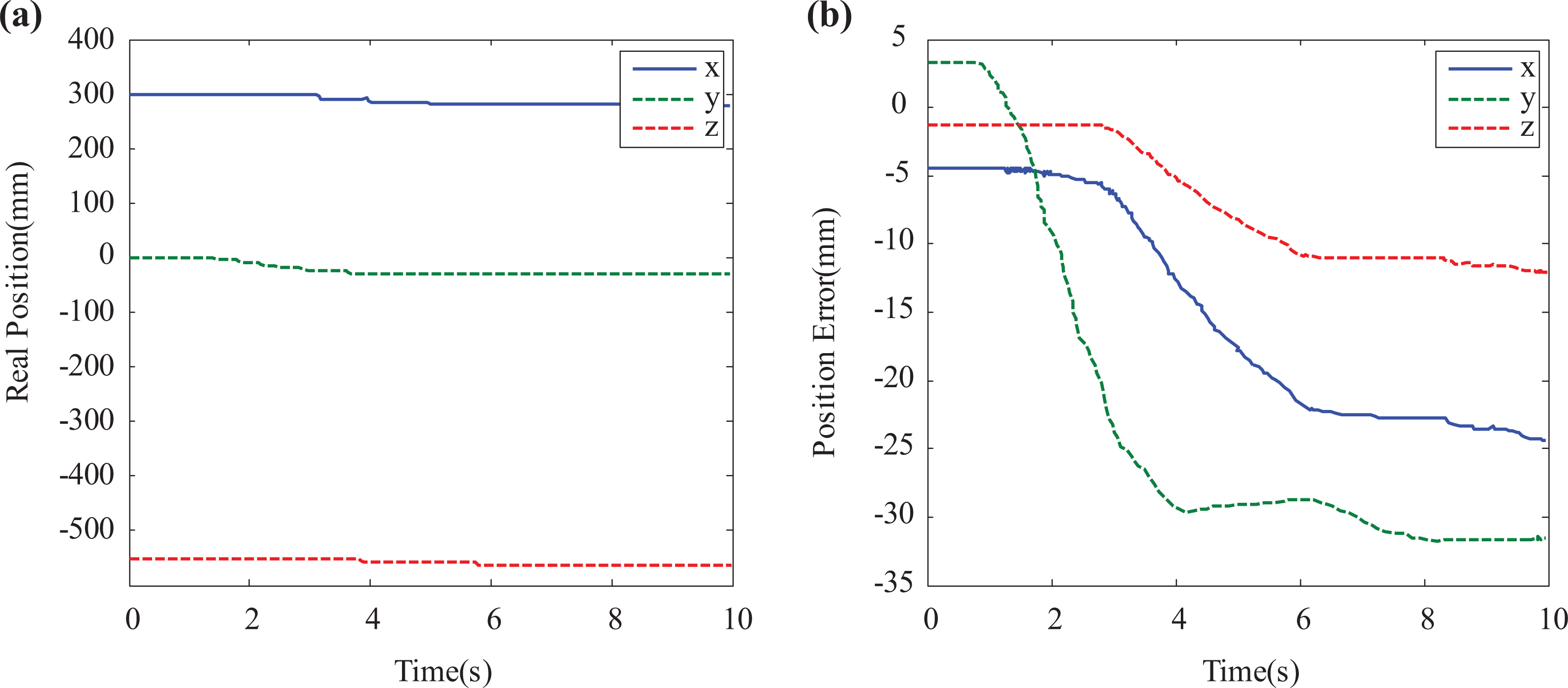
Experimental results of the general impedance control. (a) Real position and (b) position error.
When the null-space impedance control method is used (Figure 6(b)), the position of the object remains almost unchanged (as shown in Figure 8(a)) and the position error caused by human interaction gradually converges; the dynamic position error is less than 4 mm and the steady-state position error is less than 2 mm, which meets the experimental requirements less than 5 mm (Figure 8(b)).

Experimental results of the null-space impedance control. (a) Real position, (b) position error, (c) external force, and (d) arm angle misalignment.
Therefore, under the control of null-space impedance, as the external force acts on the arm (Figure 8(c)), the arm angle of the manipulator changes (Figure 8(d)) and self-motion occurs. To investigate the influence of the null-space impedance parameters on the change in the arm angle, three groups of null-space impedance parameters were selected in the experiment, as shown in Table 3.
Three groups of null-space impedance parameters.

A comparison of the curves a and b (Figure 8(d)) indicates that the damping DN is doubled and the speed of the arm angle is reduced by half. For example, when the arm angle is changed to 6°, group a requires 2.5 s, whereas group b requires 5 s. A comparison of the curves a and c demonstrates that the stiffness KN is doubled and the steady-state value of the arm angle is reduced from 9.3° to 4.7° (about one-half). The experimental results are consistent with the simulation results and indicate that by adjusting the impedance parameters, the null-space motion of the manipulator can be controlled and the impedance relationship can be satisfied.
In summary, it is concluded that the manipulator is susceptible to external force disturbance when the general impedance control method is used. By controlling the self-motion of the manipulator, the null-space impedance control ensures that the object remains stable when the manipulator is disturbed by an external force.
Conclusion
In this article, a redundant manipulator null-space impedance control method was presented. Compared with the general impedance control method, the advantage of this method is that the 7-DOF redundant manipulator retains the Cartesian space impedance characteristics while achieving null-space impedance control. When an external force was applied to the manipulator, the proposed method ensured that the null-space of the manipulator also achieved the compliant behavior and the position error of the Cartesian space converged asymptotically.
To achieve these results, the concepts of the compliant plane and the arm plane were introduced. The algebraic difference between the two planes (i.e. the arm angle) was used to describe the null-space motion of the manipulator and the null-space impedance equation, which contained a stiffness term, is derived according to the energy theory. The expression has a clear physical meaning and the equation was combined with the dynamic equation to establish an extended impedance control equation. The purpose of this derivation was to provide a physical description of the manipulator’s null-space rotational stiffness in the angular domain and obtain an analytical solution for null-space motion acceleration control. Simulations and experiments using a non-null-space impedance control method and the null-space impedance control method verified the effectiveness of the proposed method.
Footnotes
Declaration of conflicting interests
The author(s) declared no potential conflicts of interest with respect to the research, authorship, and/or publication of this article.
Funding
The author(s) disclosed receipt of the following financial support for the research, authorship, and/or publication of this article: This work was supported by the National Key R&D Program of China (2018YFB1305300) and the National Natural Science Foundation of China (NSFC, 61763030, 61263045, and 51265034).