
Abstract
Real-time recognition of walking-related activities is an important function that lower extremity assistive devices should possess. This article presents a real-time walking pattern recognition method for soft knee power assist wear. The recognition method employs the rotation angles of thighs and shanks as well as the knee joint angles collected by the inertial measurement units as input signals and adopts the rule-based classification algorithm to achieve the real-time recognition of three most common walking patterns, that is, level-ground walking, stair ascent, and stair descent. To evaluate the recognition performance, 18 subjects are recruited in the experiments. During the experiments, subjects wear the knee power assist wear and carry out a series of walking activities in an out-of-lab scenario. The results show that the average recognition accuracy of three walking patterns reaches 98.2%, and the average recognition delay of all transitions is slightly less than one step.
Keywords
Introduction
In recent years, with the acceleration of the aging population, the proportion of elderly citizens has become larger, thus life quality of elderly citizens is an increasingly prominent issue. With the increase of age, the organ function and muscular strength of the elderly gradually decline, moreover, the strength decline in lower extremities is especially obvious. For the elderly, muscular degeneration leads to walking ability decline, which greatly affects their life quality. In addition, some injuries can also seriously influence walking capacities, such as soft tissue injuries, ligament strains, flexor extensor injuries, and so on. Because of these injuries, the elderly cannot walk as normal people, and they even walk in abnormal gaits. To deal with these problems, on the one hand, the gait parameters of these groups need to be detected to facilitate gait assessment, and on the other hand, some devices are needed for rehabilitation training and assistance. Yang et al. 1,2 developed a very compact wearable accelerometry system for real-time gait cycle parameter recognition. These gait cycle parameters include cadence, step regularity, stride regularity, and step symmetry.
With the intensification of aging, the robotic demands in fields of medical rehabilitations and walking assistances become higher and higher, therefore more wearable assistive devices have been developed to solve the problems of walking ability loss. The traditional rigid lower extremity exoskeletons can realize human performance augmentation, rehabilitation training, and walking assistances, such as ReWalk, 3 HAL, 4 and Ekso. 5 However, these existing lower extremity exoskeletons are designed with rigid structures, which are uncomfortable to wear, heavy in weight, large in inertia, and expensive. Thus, some researchers are interested in the development of soft actuators and develop a variety of soft lower extremity rehabilitation and assistive devices. 6 –12 The application of soft actuators greatly reduces the weight of lower extremity assistive devices and increases the flexibility at joints during walking.
As to the development of both rigid lower extremity exoskeletons and soft lower extremity exoskeletons, it is crucial to take the influences of outdoor terrain into account, since in addition to the level ground, the actual walking environment also includes stairs. Hence, lower extremity exoskeletons controlled by a fixed control algorithm must affect the normal movement of humans, even have serious impacts on human body. To improve the application of lower extremity exoskeletons in daily life, the controller should recognize human locomotion modes and carry out corresponding control strategies, thus research on real-time locomotion mode recognition is basic but significant.
Locomotion mode recognition is generally a process including signal acquisition, feature selection, feature extraction, and classification. Many locomotion mode recognition methods have been proposed in recent years. Electromyography (EMG) signal is one of the most important biological signals for the locomotion mode recognition, which can reflect whether human muscles are activated. Therefore, some researchers employ EMG signals to related research on human locomotion mode recognition. 13 –16 However, there are still some limitations. For example, during EMG signals collection process, the electrode should be fixed on wearers’ skin surface, which is inconvenient in practical applications. 17 Moreover, the displacement of the electrodes or sweating skin will affect data acquisition. Therefore, more and more researchers prefer to use mechanical sensors instead of EMG electrodes to increase its dependability. Ground reaction force (GRF) reflects the distribution of plantar pressure during human walking, so GRF can be regarded as an important human gait feature. Some researchers apply GRF signals to the locomotion mode recognition 18 –21 and take GRF signals together with other sensor signals as input, such as signals from attitude and heading reference systems, inertial measurement units (IMUs), encoders, and so on. GRF signals can be detected by various pressure sensors attached to foot soles. However, since pressure sensors are always under pressure in use, service life of sensors will be greatly shortened. In addition, when wearers walking on complex terrain like rugged roads, or when in the swing phase, it is difficult to extract features through GRF signals.
Furthermore, some researchers chose other types of sensors to collect input signals to achieve locomotion modes recognition. Wang et al. 22 proposed a flexible lower extremity exoskeleton with deep locomotion mode recognition. In this recognition algorithm, angle data of hip, knee, and ankle joints collected by the encoder were taken as input features, and the deep locomotion mode recognition model based on long short-term memory was adopted. In addition, the IMU is a small, low-cost, relatively easy-to-wear sensor and can collect a variety of information such as angle and acceleration. Therefore, IMU has been used more and more widely. Jang et al. 23 proposed an online gait task recognition algorithm for hip exoskeleton. This algorithm could estimate the moment when foot contacting ground based on the vertical acceleration provided by the IMU installed on human back. And two potentiometers mounted on hip joints could measure the left and right hip joint angles. Finally, through the hip joint angles relationship between two legs at the moment when foot contacting the ground, gait task recognition could be achieved. Besides above research, Zhang et al. 24 used four IMUs and a laser sensor to predict the height of the terrain in front of the wearers. David and Hsiao-Wecksler 25 proposed a threshold-based method that adopted IMU to track the location of ankle–foot orthosis and recognized the gait mode by location information.
To improve the recognition performance, some researchers have adopted a multi-sensor fusion method. 26 –31 Liu et al. 30 proposed a recognition method for sit-to-stand and stand-to-sit transitions based on the multi-sensor fusion information from a potentiometer and three IMUs. The average recognition accuracy of the five able-bodied subjects was 97.37%. Multi-sensor fusion method can improve recognition accuracy, but it will increase the complexity of robotic system, and it tends to lead to poor robustness and poor environmental adaptability. Moreover, the combination of a number of sensors increases the difficulty of calculation and processing, which may slow down the recognition process.
Performance of recognition methods depends not only on the sensory system but also on the classification techniques. Some researchers employed fuzzy-logic 18,23,32 and threshold-based methods. 25 To effectively improve the recognition accuracy, increasing machine learning methods were used for the locomotion mode recognition, such as support vector machine, 19,30,33,34 decision tree, 35 neural network, 20,21 and so on. Because convolutional neural network (CNN) has the potential to extract features from high-dimensional data automatically, researchers were interested in using CNN for locomotion mode recognition recently. 36 –38 Lee et al. 36 used CNN to recognize staying still, walking, and running from accelerometer data, and the recognition accuracy was only 92.71%. Feng et al. 38 proposed a locomotion mode recognition method based on CNN and one-dimensional signals from strain gauge mounted on the active prosthesis. This method could recognize three locomotion modes of level ground, ascent terrain and descent terrain, and the overall recognition accuracy was 92.06% in the hold-out test. Chowdhury et al. 39 proposed ensemble learning algorithms for the classification of physical activities using wrist worn accelerometer. The authors compared the performance of single classifier algorithms, custom ensemble method, and conventional ensemble methods. The results showed that the custom ensemble method that fused several single classifiers achieved higher recognition accuracy of 85.99%. But these methods usually extract multidimensional features, which increases algorithm complexity, as well as the cost of calculation and storage. These problems will limit its widely application. In addition, machine learning methods demand a large amount of training data and need to manually segment each data sample. This process is quite time-consuming and cumbersome, and even some of the target data are difficult to collect in a large amount.
In addition, more research currently focused on using only the sensor systems to realize the recognition of human locomotion mode or the application on prostheses, and less research have been done around lower extremity assistive devices. Moreover, many algorithms for human locomotion mode recognition are implemented and evaluated off-line, and only a few among them have verified the real-time recognition performance of the system. Before recognition methods are actually applied to the lower extremity assistive devices, it is very important to verify the real-time recognition performance.
To overcome these limitations of current recognition methods, we propose a real-time walking pattern recognition method that uses only a single type of low-cost, high-reliability sensor, and with less calculation, small storage, low hardware requirements and good recognition performance. This recognition method only employs the rotation angles of thighs and shanks as well as the knee-joint angles collected by IMUs as input signals and adopts the rule-based classification algorithm to achieve the real-time recognition of three common walking patterns, that is, level-ground walking (LW), stair ascent (SA), and stair descent (SD). In addition, the proposed method is more convenient for practical application and porting to other similar devices since the method uses only IMU sensors commonly used in wearable devices and does not need to use a large number of training sets for training. In this article, the proposed recognition method is implemented on soft knee power assist wear. Because this method only makes use of the sensors installed in the knee power assist wear instead of additional ones installed on human body, this simplifies the entire structure of soft knee power assist wear and becomes more convenient for wearers.
Soft knee power assist wear
Recently, we developed a knee-joint assistive soft exoskeleton called “soft knee power assist wear,” which consists of soft knee-joint executive devices, a control box, IMUs, and so on, as shown in Figure 1(a). As shown in Figure 1(b), the soft knee-joint executive device consists of a curved pneumatic actuator, a linear pneumatic actuator, and an intermediate support airbag. The intermediate support airbag is fixed to the leg by knee guards, and it can transmit the torque generated by both curved pneumatic actuator and the linear one to the knee joint. To make the power assist wear’s structure more compact and portable, the controller, pneumatic system, and a battery are integrated into the control box. The pneumatic system of the power assist wear is mainly composed of a micro air pump, micro solenoid valves, and so on. As to the data processing, control commands, opening and closing of the air pump, and the solenoid valve, they are all controlled by the designed controller.

Soft knee power assist wear: (a) Overall structure of the soft knee power assist wear; (b) structure of the soft knee-joint executive device.
When to aerate the linear pneumatic actuator, the actuator generates an extension torque to straighten the knee joint; when to aerate the curved pneumatic actuator, the actuator generates a bending torque to bend the knee joint. The power assist wear can provide assistive torque about 10–20% of biological moment to help wearers walk on level ground, ascend stairs, and descend stairs. It can not only help healthy people to save energy but also assist the elderly to enhance mobility. Since the knee-joint executive device is made of soft cloth and it weighs only 112 g, it can be deflated and folded when it is not in use. Then people who travel far away can also carry and use it. This portable feature greatly expands its application.
Walking pattern recognition method
In our daily life, most roads in our country are horizontal asphalt pavement or stairs. And most dwellings are still old-fashioned residential buildings with six floors however without elevators. Therefore, LW, SA, and SD are three most common daily activities. According to previous kinematic and dynamic studies about human lower extremities during walking, 40 –43 it can be found that there are still significant differences in biomechanical characteristics of knee joints in three different walking patterns. Then, to achieve the goal that the knee power assist wear can provide an auxiliary torque for human body during walking, the torque generated by the power assist wear should adapt to biological moment in different walking patterns. Therefore, based on the information collected by the sensor, the controller has to recognize the current walking pattern.
Hardware system
The hardware system for target walking pattern recognition consists of a controller, four IMUs, a battery and a laptop, as shown in Figure 2. This system is responsible for lower extremity kinematic information collection and walking pattern recognition. When this system is in use, the rotation angles of left and right thighs, rotation angles of left and right shanks, knee-joint angles, and walking pattern recognition results are transmitted to the laptop through serial ports and displayed in real time.
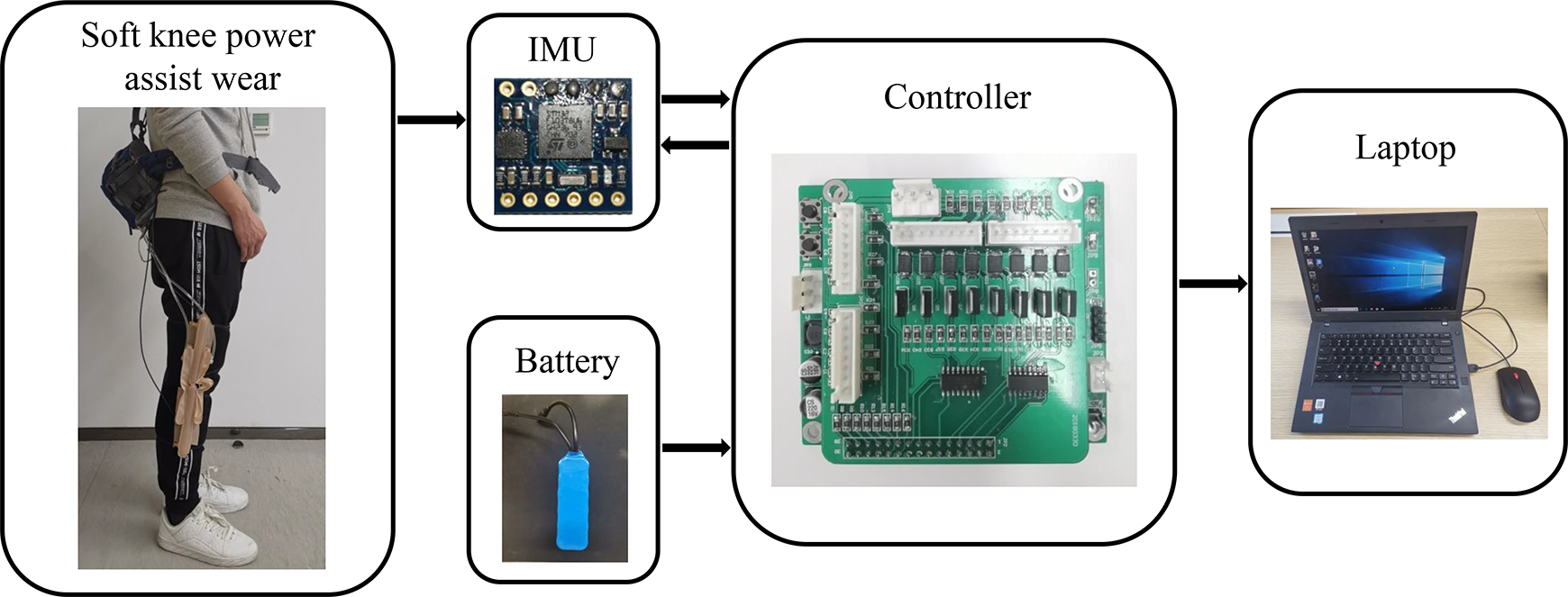
Schematic diagram of hardware system.
Four IMUs are adopted to acquire signals in order to obtain sufficient information of lower extremities, then the power assist wear can achieve motion control. Furthermore, we install IMU GY-953 in the power assist wear due to its high reliability and wide application. GY-953 consists of a three-axis gyroscope, a three-axis accelerometer, and a three-axis magnetometer. And it has a measurement range of −180° to +180° and a resolution of 0.1°. It can directly output different kinds of data, such as acceleration raw data and Euler angle data.
The main movements of lower extremities execute in the sagittal plane during human walking, hence in order to measure the movements of human thighs and shanks in the sagittal plane, four outward facing IMUs are placed respectively on both lateral thighs, as well as both lateral shanks, as shown in Figure 3. According to the installation position of the IMUs, the changes of pitch angles can reflect the angular variation of thighs and shanks in the sagittal plane. In addition, when two legs perform the same actions, the pitch angles collected by the IMUs at the corresponding position on the left and right legs are opposite. The difference between the pitch angle of the right shank and that of the right thigh is the knee-joint angle of the right leg. And the difference between the pitch angle of the left thigh and that of the left shank is the knee-joint angle of the left leg.

Demonstration of IMUs and pitch angles. IMU: inertial measurement unit.
Feature selection
To distinguish the three walking patterns of LW, SA, and SD, we need to clear the angle changes laws of thighs, shanks, and knee joints. So we recruited some subjects and collected data. In the data acquisition process, they performed three walking patterns of LW, SA, and SD. Then their movement information about thighs and shanks was collected by a laptop. Figure 4 shows angle changes trends of both legs in three walking patterns. During walking, the right leg and the left leg are moving alternately, the motion law is the same, and the only difference is reflected by the plus-minus sign, thus we only analyze motion of the left leg as an example. And to simplify the description, the angles of thighs and shanks in the following sections refer to the pitch angles.

Angle changes trends of both legs in three walking patterns.
As shown in Figure 5, when humans ascend stairs, the angle of the left shank is basically positive, and the angle variation range is small. But the angle of the left thigh is basically negative, and the angle variation range is larger than that of the left shank (b > a). The angular curves of the left thigh and the left shank almost do not overlap and the space c between angle curves is small. In addition, the absolute value of the minimum angle θa of the left thigh is large and much larger than that exported when the walking patterns are LW and SD. It also indicates that when humans are ascending stairs, the lifting height of the thighs is higher than that exported from other two walking patterns, so that humans can step on a stair.

Angle changes trends of left thigh, left shank, and left knee joint, when humans ascend stairs, walk on level ground, and descend stairs. θa represents the minimum value of the left thigh angle, θb represents the minimum value of the left shank angle, θc represents the maximum value of the left shank angle, θd represents the maximum value of the left thigh angle, and θe represents the minimum value of the left knee angle. a indicates the angular variation range of the left shank, b indicates the angular variation range of the left thigh, c indicates the space between angle curve of the left shank and the left thigh, and d indicates the angle curve coincidence range between the left shank and the left thigh.
When humans walk on level ground, the angle of the left shank fluctuates back and forth between positive and negative. The angle curves of the left thigh and the left shank overlap a lot below 0°, and coincidence range d of the two angle curves is large. Among the three walking patterns, only in LW pattern, the angle curves are coincident a lot. This feature is unique. Further, in LW pattern, the minimum value θb of the left shank angle is a small negative value and θb is smaller than that exported from the other walking patterns.
When humans descend stairs, the angle of the left thigh is always a negative value, and the angle variation range is small. The angle value of the left shank changes back and forth between positive and negative. Most of the time it is positive, and the angle variation range of the left shank is much larger than that of the left thigh (a > b). The angle curves of the left thigh and the left shank do not overlap and the space c between angle curves is large. In addition, the maximum value θc of the left shank angle is significantly larger than that exported from other two patterns. The maximum value θd of the left thigh angle is smaller than that exported from other patterns. The left knee-joint angle curve illustrates that the absolute value of minimum value θe of the left knee angle is the largest among three patterns.
Based on analysis above, it can be seen that, as to the three walking patterns, angle changes trends of the ipsilateral thigh, shank, and knee joint are completely different, and there are even obvious differences on some features among these three walking patterns. To represent and describe these features, 10 angular parameters are selected as input signals. Here, leftup_high indicates the maximum value of the left thigh angle, leftup_low represents the minimum value of the left thigh angle, leftdown_high refers to the maximum value of the left shank angle, and leftdown_low represents the minimum value of the left shank angle. Following this rule, rightup_high and rightup_low, respectively, represent the maximum and minimum value of right thigh angle; rightdown_high and rightdown_low, respectively, correspond to the maximum and minimum value of right shank angle; kneeangle_left_Min indicates the minimum value of the left knee angle; and kneeangle_right_Min refers to that of the right knee angle. All the selected features can be represented by these angular parameters, as shown in Table 1.
Selected features.

Among them, flexion angle of the hip joint is positive, extension angle of the hip joint is negative; forward swing angle of the shank with the knee-joint extension is positive, back swing angle of the shank with the knee-joint flexion is negative; flexion angle of the knee joint is positive, extension angle of the knee joint is negative; space between angle curve of the shank and the thigh is positive, and coincidence range between them is negative.
Rule-based classification algorithm
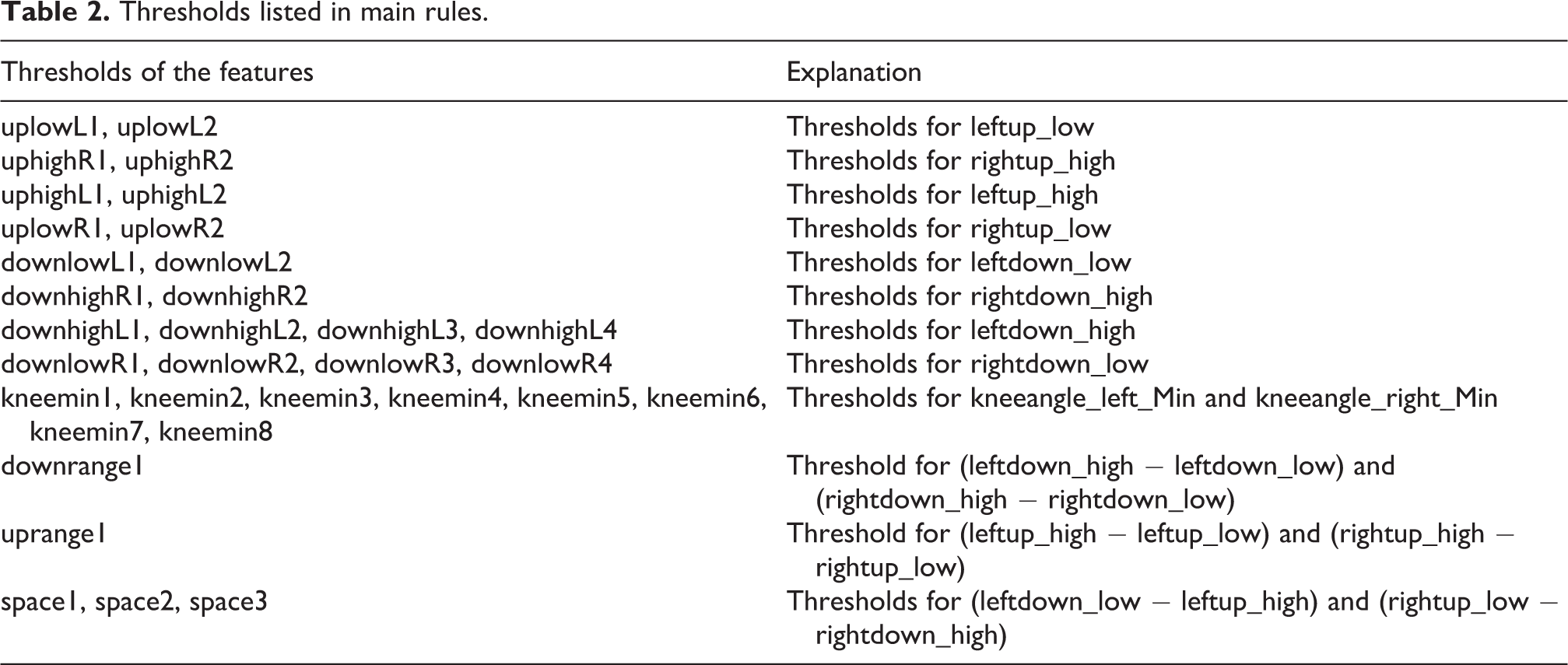
After determining the features to distinguish three patterns, a rule-based classification algorithm is proposed. As to this algorithm, each rule consists of features and thresholds following lower extremity movement laws. To unify program writing, we remove the minus sign of features in relational expressions composed of features and thresholds. To determine the rules in the algorithm, we first collected angle data of thigh, shank, and knee joint of a total of approximately 2300 gait cycles from the subjects in three walking patterns. The values of the same feature of all subjects in the same walking pattern are averaged to obtain the reference value. According to personal experience, a value is selected from the maximum value, the minimum value, and the reference value of each feature as a threshold in the rule. After that, the data are used again to validate the recognition performance of the algorithm and to find out the rule leading to misjudgments. The final classification algorithm is determined by the constant adjustment of the thresholds in the rules of misjudgments and the constraints of the composition rules. The final classification algorithm consists of these rules including features of both legs. Since the movements of left leg and right leg are alternated, the motion law of both legs is basically the same except for plus and minus sign. Only several main rules and thresholds are listed here and some of them are only rules for one leg. The detail is listed in Tables 2 and 3.
Thresholds listed in main rules.
Main rules for the algorithm.
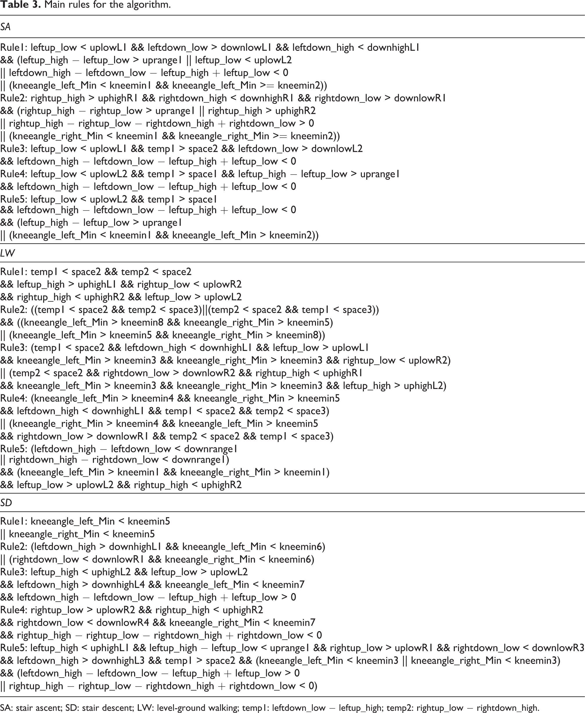
SA: stair ascent; SD: stair descent; LW: level-ground walking; temp1: leftdown_low − leftup_high; temp2: rightup_low − rightdown_high.
In the classification algorithm, each rule is composed of multiple relational expressions connected through logical operators, and each relational expression is a constraint on selected features. Since walking law of each person is different, to ensure recognition performance, we have not only selected a variety of distinctive features to distinguish walking patterns but also combined different constraints in various ways. Only when the current motion laws of thighs, shanks, and knee joints conform to the constraints of multiple features of a certain pattern, the pattern can be judged as the certain one.
In addition, an automatic calibration is designed to eliminate the impacts brought by the inaccurate position of IMUs. The controller calibrates automatically when it is powered on. During calibration, the wearer needs to stand still for 2 s. At this moment, the controller stores the initial angle value collected by the IMUs and sets start angle values of thighs and shanks to 0° in standing state, then the wearer can walk normally. Thereafter, all the angle values collected by the IMUs will subtract the initial values to obtain the final angle values relative to the start angle in stand still state for target recognition algorithm.
The process of walking patterns recognition is shown in Figure 6. After the beginning of the recognition, the controller calibrates automatically and then the features of current walking pattern will sequentially match the rules of SA, LW, and SD at the beginning of each cycle. If the features of current walking pattern conform to the preset rules of a certain pattern, the program will export the corresponding walking pattern as the output. If the features of current pattern don’t conform to any rules of all walking patterns, then the current pattern at this cycle will be considered to be the same as the previous one. To check the result of recognition easily and to provide necessary information for control algorithm of the knee power assist wear, the ID is recorded, which corresponds to the exported walking pattern, as shown in Table 4.

Flow chart for walking pattern recognition.
Walking pattern ID.

LW: level-ground walking; SA: stair ascent; SD: stair descent.
Experiments and results analysis
Experimental protocol
We invited 18 subjects to participate in the experiment to verify the performance of the proposed walking pattern recognition method, including nine males and nine females (average age: 44.72 ± 9.57 years, average body mass: 64.95 ± 11.38 kg, average height: 1.64 ± 0.09 m) whose ages ranged from 25 to 60 years. They gave their informed consent and agreed to participate in the study.
The experimental site lay in a modern office building. At the beginning of an experiment, in unpowered knee power assist wear, a subject kept standing for 5 s and began to walk on level ground for 25 m. Then the subject climbed four floors and walked on level ground for 50 m. After LW, the subject returned to the original floors and walked on level ground for 25 m. The whole experiment process is shown in Figure 7. During the experiment, a researcher will follow the subject to complete the whole experiment and record the experiment process. Since subjects’ walking speeds were not limited, they could perform all activities at the speed they preferred. The proposed recognition method recognized the walking pattern in real time and displayed the recognition results, the angles of the thighs and shanks as well as knee-joint angle data on the laptop simultaneously.

Walking pattern recognition experiments: (a) LW; (b) SA; (c) SD. LW: level-ground walking; SA: stair ascent; SD: stair descent.
Results analysis
In this section, we adopt recognition accuracy (RA) and recognition delay rate (RDR) as two indicators to evaluate the real-time recognition performance toward three walking patterns and the transition among different walking patterns.
Recognition accuracy
RA indicator is introduced to evaluate the accuracy of the classification algorithm. RA is defined as

N correct is the number of correct recognitions, and N total is the total number of recognitions.
The recognition results of 18 subjects are analyzed and processed in this section, and according to ages of subjects, the results are separated into two groups for comparison. Three confusion matrices are shown in Tables 5 to 7. The elements of confusion matrices are presented by the format of mean and standard error. As shown in Table 5, through the proposed recognition method, the average RA toward each walking pattern of all subjects is higher than 98%, and the average RA of three walking patterns can reach 98.2%. In addition, although subjects come from different age groups, the recognition accuracies of two groups toward a same walking pattern are not different obviously, as shown in Tables 6 and 7. Taking the RA of subjects from 25 to 44 years group for reference, 98.80% of their LW pattern can be recognized successfully which is the highest accuracy among three patterns of this group. As for subjects from 45 to 64 years group, the accuracy of SA walking pattern reaches 98.81%, which is the highest.
Confusion matrix for experimental results of all subjects.
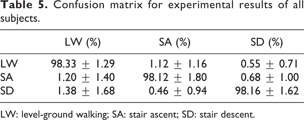
LW: level-ground walking; SA: stair ascent; SD: stair descent.
Confusion matrix for experimental results of 25–44 years group.

LW: level-ground walking; SA: stair ascent; SD: stair descent.
Confusion matrix for experimental results of 45–64 years group.
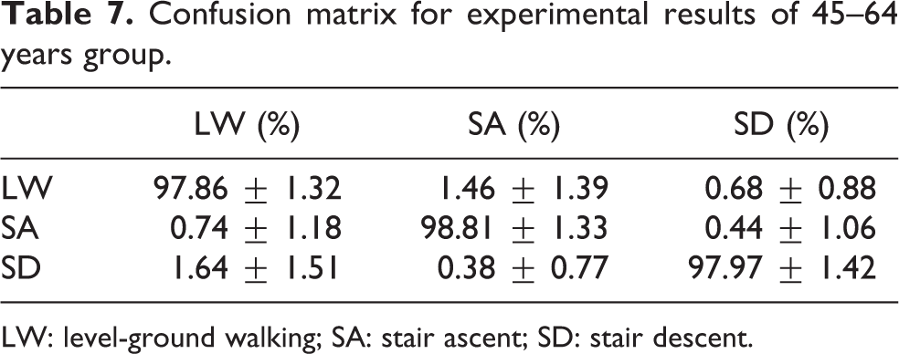
LW: level-ground walking; SA: stair ascent; SD: stair descent.
According to analysis above, the proposed walking pattern recognition method can recognize LW, SA, and SD walking patterns precisely and the recognition performance will not be affected by ages. Thus, the method can be applied to the lower extremity exoskeletons, so that exoskeletons can adopt more effective control strategies to assist human walking according to different walking patterns. The recognition of LW, SA, and SD walking patterns can basically meet the needs of human daily motion activities.
Recognition delay during transitions
Figure 8 shows partial recognition process of a subject during the experiment. The controller collects the angles of both thighs and shanks in real time and calculates both knee-joint angles. The rule-based classification algorithm recognizes the current walking patterns each cycle and exports the walking pattern ID.
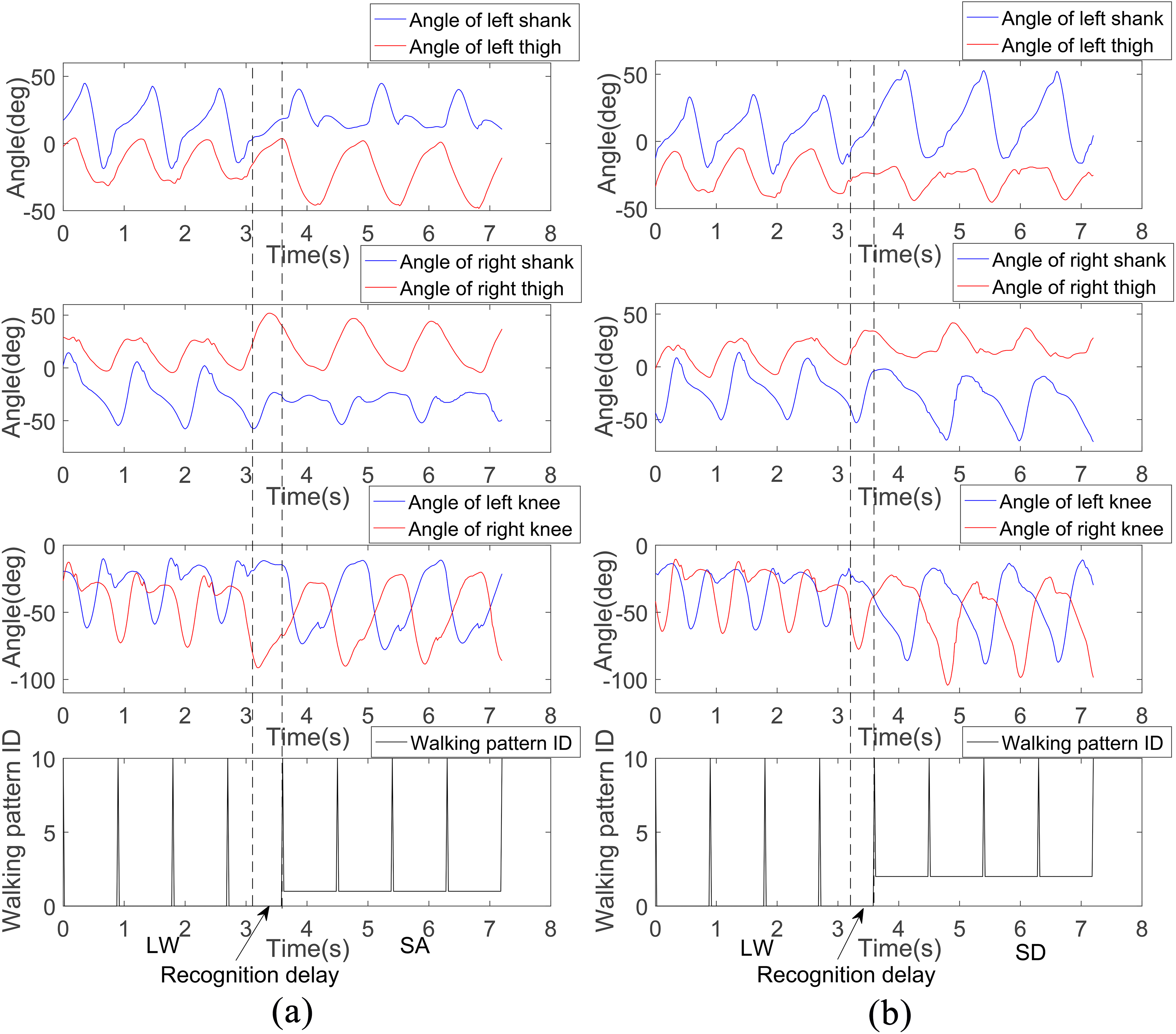
The curve of the lower extremity angle and the recognition results of a subject before and after the two transitions: (a) The curve of the lower extremity angle and the recognition results during patterns of LW, SA, and LW to SA; (b) the curve of the lower extremity angle and the recognition results during patterns of LW, SD, and LW to SD. In walking pattern ID diagram, the ordinate value 0 represents LW pattern, 1 represents SA pattern, and 2 represents SD pattern. The present of a mutation peak means the controller performs walking patterns recognition once, and the time difference between the dashed lines indicates the recognition delay during transition. LW: level-ground walking; SA: stair ascent; SD: stair descent.
In the case of normal walking, the transitions between SA and SD walking patterns usually need to go through LW pattern. So it can be concluded that there are four transitions, including transitions from LW to SA, SA to LW, LW to SD, and SD to LW. Strictly speaking, transitions cannot be regarded as a standard walking pattern among three patterns. The former movement part during transition is still the previous pattern and the latter part is the later pattern. The detail of transition is shown in Figure 8. To evaluate whether the method can recognize the transition on time, it is necessary to calculate the time difference between the critical moment (the time when the wearer starts to change the current walking pattern) and the recognition moment (the time when the controller accurately recognizes the subsequent pattern). RDR indicator is introduced to measure the recognition delay, which is defined as:
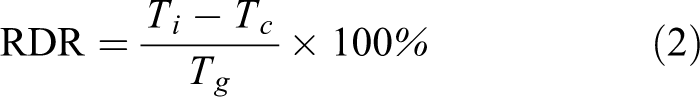
where Ti represents the recognition moment, Tc represents the critical moment, and Tg represents the average gait cycle.
According to definition above, as to the example in Figure 8, the delay of the wearer from LW to SA is 486 ms, which is approximately 38.23% of the gait cycle, and the delay from LW to SD is 398 ms, which is approximately 30.47% of the gait cycle. Then the average RDR of all wearers is calculated to evaluate the pattern recognition performance during transition, as shown in Table 8. The RDRs of LW to SA and LW to SD are 47.53 ± 17.68% and 41.11 ± 11.24%, respectively, which can be considered to be relatively small. However, the RDRs of SA to LW and SD to LW are 58.16 ± 13.78% and 50.01 ± 13.47%, respectively, which can be considered to be relatively high. Through analysis, it can be found that the angle amplitude of the thigh and shank is small in the LW, while the angle amplitude of the thigh is large in the SA, and the angle amplitude of the shank is large in the SD. Therefore, during transition from SA to LW or from SD to LW, the LW pattern cannot be recognized immediately. It makes the controller take more time to recognize LW pattern and result in a longer delay. After calculation, it can be obtained that the average RDR of four transitions is 49.2%.
Average RDR (mean ± standard deviation) during transitions among all wearers.

RDR: recognition delay rate; LW: level-ground walking; SA: stair ascent; SD: stair descent.
In addition, Table 8 presents that there is a certain standard deviation for each transition, which indicates that the length of recognition delay varies from person to person. For example, for one subject, the RDR of SA to LW is only 30.26%, while the RDR of another subject is 61.37%. To evaluate dispersion degree of the RDR of different subjects during the same transition, coefficient of variation is introduced, which is the ratio of the standard deviation to the mean. It can be obtained by calculation that the coefficients of variation of the proposed method are 0.37, 0.24, 0.27, and 0.27, respectively, which are relatively small. It shows that the recognition delay for different subjects has less fluctuation. Although there is a certain delay through this method, the result will not have serious impacts on human body, since the knee power assist wear is flexible and only provides partial assistance to the wearer. In future research, the negative impacts on human body may be reduced by adding the walking pattern prediction algorithm.
Discussion
This article proposes a real-time walking pattern recognition method for the knee power assist wear. The method exploits the angle information collected by four IMUs installed on knee power assist wear as input signals and adopts a rule-based classification algorithm to recognize the three walking patterns of LW, SA, and SD. The method does not require other kinds of sensors and does not need a large number of training sets. The calculation is simple, the storage amount is small, and the practical application is convenient. To evaluate the recognition performance of the method, we selected 18 subjects to conduct experiments. Experimental results show that the method has good real-time recognition performance.
There are also two recognition methods only adopting motion sensors to acquire input signals and extracting kinematics features. In the deep locomotion mode recognition method, 22 the researchers make use of the experimental data of 18 healthy men to off-line learning and experimental data of four healthy men to test the algorithm performance. The experimental results show that the recognition success rates of locomotion modes of LW, SA, and SD are 99.4%, 97.22%, and 96.02%, respectively, and the average recognition success rate of all locomotion modes is 97.55%. Moreover, the RDRs of transitions among three patterns are different. The strict RDR of SD to LW transition is the least 31.29 ± 13.3%, while the delay rate of LW to SD transition is up to 47.69 ± 28.77%. The strict RDR of LW to SA transition is 37.51 ± 29.04%, while the delay rate of SA to LW transition is 33.75 ± 10.87%. The average RDR of four transitions is 37.56%. The other recognition method is an online gait task recognition algorithm, which adopts a fuzzy inference system to recognize three patterns. 23 Through tests on three healthy men, recognition accuracies of LW, SA, and SD patterns are 99.1%, 97.9%, and 95.3%, respectively, and the average recognition accuracy is 97.4%. In addition, this algorithm has a one-step recognition delay.
In this experiment, we invited more subjects to verify the performance of the proposed method. The recognition accuracies of walking patterns of LW, SA, and SD among 18 participants reach 98.33%, 98.12%, and 98.16%, respectively. The average RA is 98.2%, which is closer to that of two recognition methods above. It indicates that the proposed method has a good recognition performance. In addition, as to the proposed method, the RDRs during transitions are also different, and the average RDR is 49.2%. At this aspect, there is not much difference among current mainstream locomotion mode recognition algorithms, and many recognition algorithms have one-step delay. 23,25,32 It can be seen that the standard deviation of RDR during transitions of the first method mentioned above is also large, which indicates that the RDR varies from person to person. It can be obtained by calculation that the coefficients of variation of the first method during LW to SA, SA to LW, LW to SD, and SD to LW are 0.77, 0.32, 0.6, and 0.43, respectively, while the coefficients of variation of the proposed method are 0.37, 0.24, 0.27, and 0.27, respectively, which are smaller. It shows that although the proposed recognition method has a longer recognition delay, the recognition delay for different subjects fluctuate slightly, which proves that the influence from different subjects on the target method is less. In addition, since the proposed method is a white box method, there is still room for further improvement and optimization in the future. For example, more features can be selected to improve RA and reduce recognition delay.
There are still some problems and limitations. We will try to select more features and further reduce delay while ensuring high RA. Up to now, we have only conducted experiments on subjects in unpowered knee power assist wear. In the future, after developing the control algorithms for different walking patterns, we will further verify the performance of the recognition method. If the knee power assist wear needs to meet other functional requirements, we will further refine to recognize more patterns.
Conclusions
LW, SA, and SD are three most common daily activities. As to the three walking patterns, the biomechanical characteristics of human lower extremities are different. To enable the power assist wear to assist human motion more effectively, the controller first needs to recognize the three walking patterns and then adopts corresponding control strategies to control execution of the knee power assist wear. Thus, this article proposes a real-time walking pattern recognition method for soft knee power assist wear. The method exploits the angle information collected by four IMUs installed on power assist wear as input signals and adopts a rule-based classification algorithm to recognize the three walking patterns of LW, SA, and SD. So the proposed method is very convenient for practical applications due to less calculation, small storage, low hardware requirements, and it does not need to use a large number of training sets. Through the experiments on 18 subjects, the average RA of three walking patterns is up to 98.2%, and the average recognition delay of all transitions is slightly less than one step. Therefore, the proposed method can be well applied to the knee power assist wear.
Footnotes
Declaration of conflicting interests
The author(s) declared no potential conflicts of interest with respect to the research, authorship, and/or publication of this article.
Funding
The author(s) disclosed receipt of the following financial support for the research, authorship, and/or publication of this article: This work was supported by the Basic Research Foundation of Beijing Institute of Technology, China (20160042030), and the Research Foundation for Soft Exoskeleton R&D, Beijing Advanced Innovation Center for Intelligent Robots and Systems, China (1780037231707).