
Abstract
This article investigates a model predictive control (MPC) with disturbance observer (DOB) for a trimaran longitudinal motion control. Firstly, to design the trimaran longitudinal motion stability controller, the mathematical model of the trimaran requires to be obtained. The hydrodynamic coefficients in the mathematical model are obtained by the computational fluid dynamics simulation. Secondly, a T-foil with the fixed attack angle is selected as an antipitching appendage. It is verified that the T-foil is effective in restraining the longitudinal motion of the trimaran through numerical simulation. Lastly, to enhance the ability of the T-foil for restraining the severe longitudinal motion, a controller based on the MPC method with DOB is designed to control the attack angle. The effect of the proposed algorithm is verified by theoretical analysis and simulation.
Introduction
Trimaran produces heave and pitch motions when sailing at high speed, which will adversely affect the navigation of the trimaran. The problem of how to restrain motion of a trimaran has caused great attention among engineers and technicians in different countries. For ship stabilization, the commonly used method is to install antipitching appendages on the bottom of the ship. Many appendages are used for ship stability like bilge keel, fin, T-foil, flap, and so on. 1 In these appendages mentioned above, T-foil has the advantages of low resistance and small impact on the speed. In this study, T-foil is selected as the antipitching appendage for a high-speed trimaran.
The fixed T-foil installed on the trimaran has a certain antipitching capability. To improve stability performance, a control system is designed to change the attack angle of the appendage. Consequently, the choice of a reasonable control algorithm is critical to the control system. T-foil and flaps on the fast ferry were effective for suppressing the longitudinal motion and the worst vertical acceleration is proposed as the PD (Proportional, Differential) controller index. 2,3 The PD controller has a simple principle, convenient application, and strong robustness, but the control accuracy is not very high. Multivariable classic control was used to decrease the motion sickness incidence of a high-speed ferry. 4,5 The essence of the multivariable class control is also a PD controller (first-order filter and second-order filter). Multivariable class controller has a better effect on ship stability than PD controller, nonetheless, it still has the disadvantage of PD controller. Using a multivariable robust control algorithm for a ferry stabilization, the result proved the effectiveness of advanced algorithm and could be used in actual marine environment. 6 In addition, adaptive fuzzy control in tracking an uncertain marine vehicle with unknown disturbances was used. 7 The method has a good control effect, even so, it is easy to misoperate when the system breaks down. Sliding mode control was used to design a ship steering autopilot. 8 In Wang et al.’s study, 9 –13 a finite-time observer-based control scheme was performed, and external disturbance could be exactly attenuated with a good performance of the tracking control. In Zhang et al.’s study, 14 based on the model predictive controller, path-following of underactuated surface vessels was achieved. A translation rotation cascade control approach and a learning control framework were represented for unmanned surface vehicles. 15,16 In Wang et al.’s study 17 a global asymptotic output tracking of nonlinear second-order systems with power integrators was proposed. These control algorithms have been widely used in the marine theory and engineering practice. In this article, considering the constraint of the T-foil, the method of model predictive control (MPC) combined with disturbance observer (DOB) is used for the trimaran longitudinal stability controller design, handling the constraint problem of the T-foil.
In this article, T-foil is selected as the antipitching appendage. As a result, the constraints of attack angle and the state of the trimaran must be considered. As is known, MPC can handle the constraint problem and convert the constraint conditions into quadratic programming while optimizing the corresponding performance index functions. 18 The control law contains the constraint condition and achieves the real-time control of the system under the premise of satisfying the constraint condition. Furthermore, the longitudinal motion control of a high-speed trimaran also expands the application of MPC. Due to the complexity of the marine environment, the trimaran sails in the wave can be encountered much unknown disturbance. Accordingly, a DOB is required to design. 19 –21 To tackle the problem of constraint and disturbance, the synthesis of MPC with DOB is proposed in this article.
In recent years, the computational fluid dynamics (CFD) simulation combined with experiment has been widely used. The numerical simulation results were consistent with the experiment. 22 –25 In this article, the mature CFD method is used to obtain the trimaran hydrodynamic coefficients.
The main contributions of this article are presented as follows: A scale geometric model of the trimaran is built based on the trimaran profile and parameters. Using the CFD simulation to calculate the hydrodynamic coefficients of the trimaran, the antipitching appendage is designed, the lift force provided by the T-foil is calculated, and the slope of the lift force curve is determined by the polynomial fitting. The model predictive controller with DOB is designed. The effective set method is used to constrain the amplitude of the attack angle of T-foil in actual application.
The structure of this article is as follows: the second section represents the model of the trimaran. In the third section, a T-foil is designed and approximately obtained the slope of the T-foil through the polynomial fitting. Then, an MPC with a DOB controller is designed and presented in the fourth section. The fifth section proves the effect of the proposed control algorithm through simulation.
Problem statement
For the control problem of the trimaran longitudinal motion, this article uses an active-controlled T-foil as the antipitching appendage. Firstly, a mathematical model of the trimaran is established. Consider the trimaran as an ordinary rigid body when the trimaran sails in marine. The forces and moments are produced as follows: buoyancy of the trimaran, the lift force, and moment generated by the trimaran and the active T-foil. The disturbance force and moment are generated by the wave, wind, and current. Through the dynamic theorem of the rigid body and the moment of momentum, the mathematical model for the longitudinal motion is shown as 26

where m is the mass of the trimaran, I is longitudinal inertia of the trimaran, x
3 is heave motion, x
5 is pitch motion, v is the velocity of the trimaran, FT
is the force generated by the T-foil, FH
is lift force of the trimaran, Fb
is the trimaran buoyancy, F
3 and M
5 are the wave disturbance force and moment,
The mathematical model in equation (1) describes the force situation of the trimaran during navigation. Typically, to design the controller, the mathematical model requires to be linearized as 27
where
Trimaran hydrodynamic
The trimaran parameters are listed in Table 1. For the trimaran studied in this article, the CFD simulation is used to obtain the hydrodynamic coefficients.
Parameters of the trimaran.

Theory of ship computational fluid dynamics
Ship CFD is based on three equations of fluid mechanics (continuity equation, momentum equation, and energy equation). The Reynolds-averaged Navier–Stokes (N-S)[Please approve the abbreviation “N-S” identified for the expansion “Navier–Stokes” is appropriate.] method is the most widely acknowledged method for describing turbulent flows. Normally, ship CFD requires to solve the N-S equation. The complete N-S equation is presented as 23


where
where μ is the dynamic viscosity.
Simulation process
The geometry model of the trimaran is built by a 3-D modeling software. To obtain the hydrodynamic coefficients in equation (2), the calculation domain is required. Figure 1 shows the calculation domain, the domain includes six faces, and the type of faces is provided in Table 2.

Calculation domain of the trimaran.
The boundary conditions.

Then, the grid is necessary for hydrodynamic coefficients of the trimaran calculation. Figure 2 shows four grid conditions. The total number of the grid is 50–600 k corresponding to grid 1 to grid 4, and the calculation result shows that the number of grids has little effect on the results. In general, the denser the grid, the more accurate the calculation results. But, the denser the grid, the larger the calculation. To accelerate the simulation process, grid 3 is selected as the calculation grid in this article and shown in Figure 3(a) and (b).
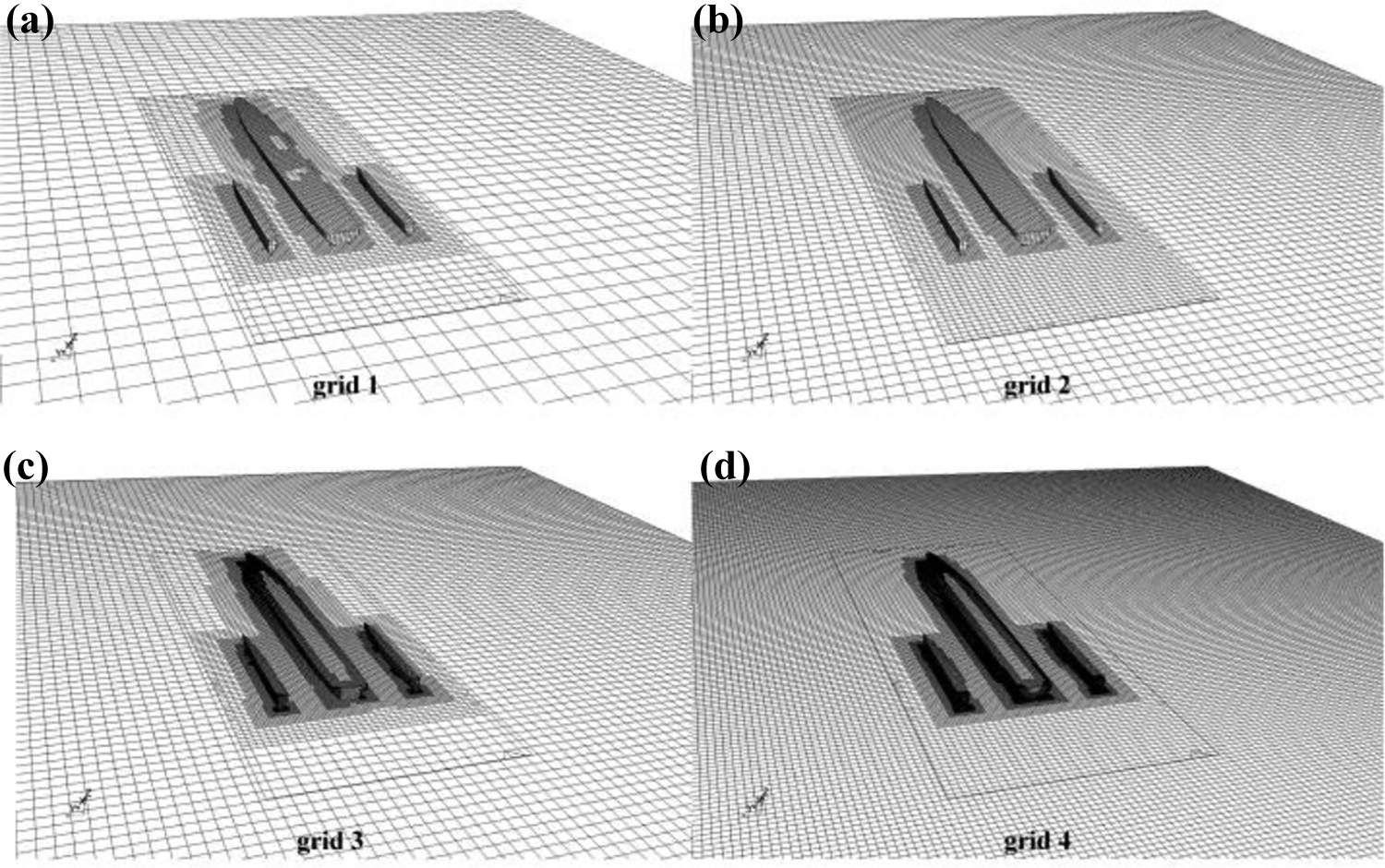
Four grid conditions: (a) grid 1, (b) grid 2, (c) grid 3, and (d) grid 4.

(a) and (b) Distribution of the grid 3.
The working conditions are given in Table 3. The
Working conditions.

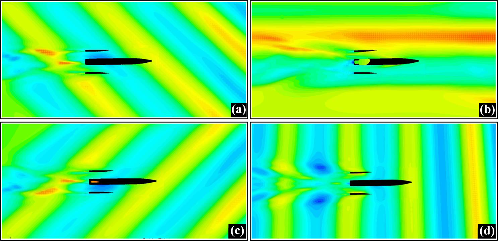
The trimaran sailing at different wave directions through CFD simulation: (a) 45°, (b) 90°, (c) 135°, and (d) 180°. CFD: computational fluid dynamics.
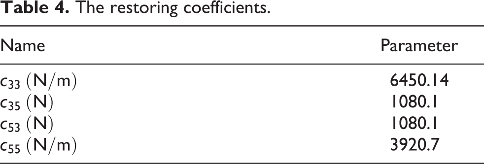
This article focuses on the trimaran sails in the heading wave. Therefore, the wave direction is set to 180°. From the CFD calculation above, the added mass and the damping coefficients are obtained and shown in Figures 5 and 6, respectively. The restoring coefficients are not changed with the speed and the encounter frequency, and Table 4 provides the restoring coefficients.

(a)–(d) Added mass.

(a)–(d) Damping coefficients.
The restoring coefficients.
Trimaran motion equation
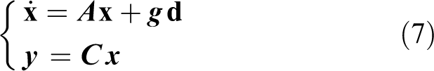
Heave and pitch motions of the trimaran are mainly influenced by external factors, such as wind, wave, and current. For the trimaran longitudinal stability controller design, equation (2) is converted to a space state equation and expressed as

For convenience, the coefficient matrix is defined as
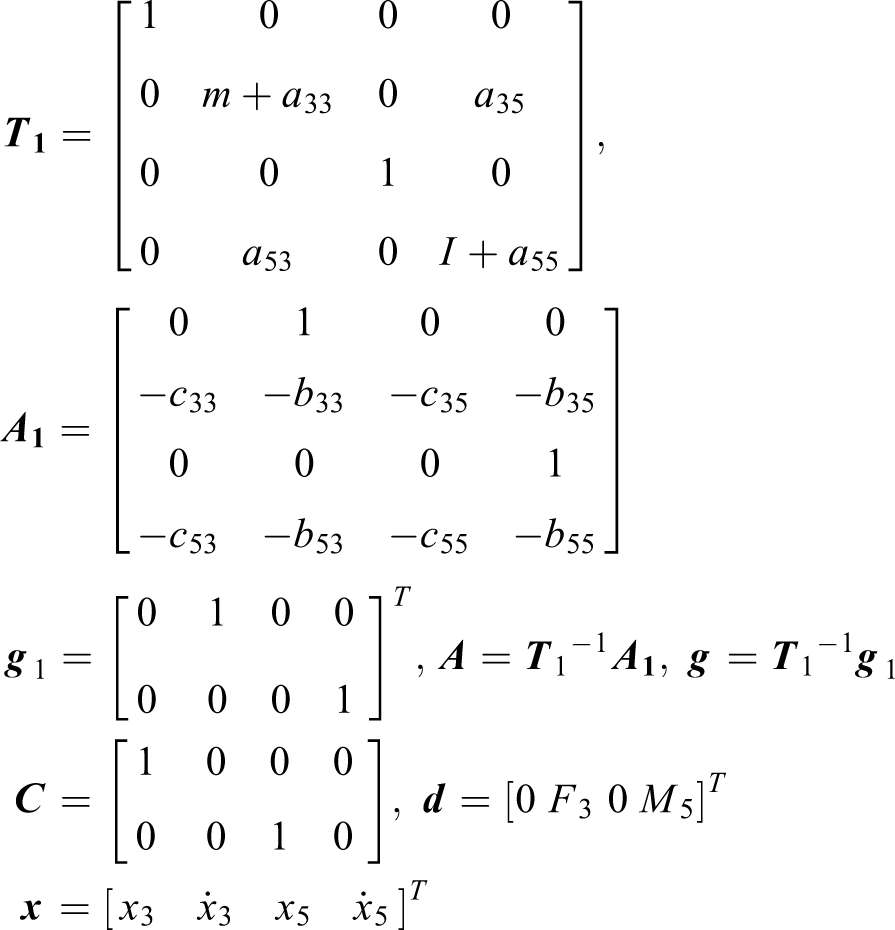
Then, the trimaran motion equation without the control force is rewritten as
Appendage design and calculation
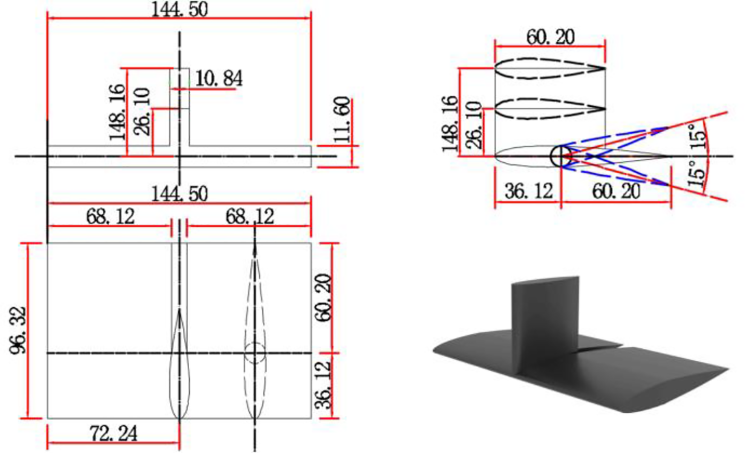
To reduce the heave and pitch motions of the trimaran, T-foil is selected as the appendage and installed on the trimaran. The airfoil type of the T-foil is NACA 0012; the size and 3-D view are shown in Figure 7.
The parameters of T-foil.
Comparison of the bare trimaran and the trimaran with the fixed T-foil
The longitudinal distance of the installation is 180 mm from the pillar centerline to the bow, and the vertical distance is 26 mm from the horizontal foil profile chord line to the trimaran baseline. Figure 8(a) and (b) shows the T-foil installation position, while Figure 8(c) and (d) shows the comparison of the bare trimaran and the trimaran with T-foil in the CFD simulation environment. Through analyzing the heave and pitch of the trimaran with T-foil and without T-foil, the result shows that the stability effect of the trimaran with fixed T-foil is better than the bare trimaran. To improve the stability effect, a controller is designed to change the attack angle of the T-foil reasonably.
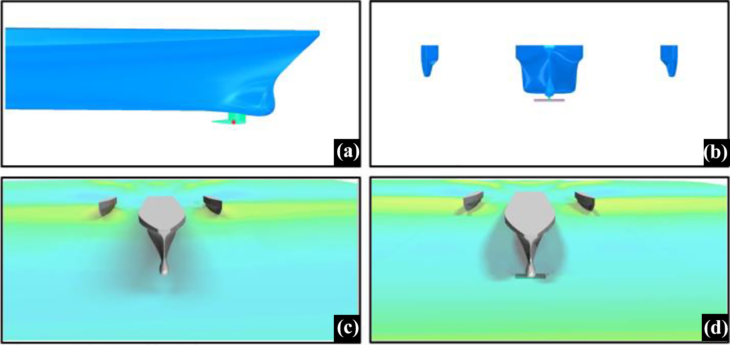
(a)–(d) Trimaran with the fixed T-foil.
Lift force of the T-foil
To design the controller, the first step is to know the lift force provided by the T-foil. Also, the lift force of the T-foil is calculated by the CFD simulation, the step is the same as the CFD analysis in the second section. Figure 7 shows the parameters of the T-foil, and the T-foil grid is shown in Figure 9. Figure 9(a) shows the overall grid of the T-foil, Figure 9(b) shows the local grid, Figure 9(c) and (d) shows the streamline and vector graph, respectively. Then, the lift force of T-foil is obtained at different attack angles.

(a)–(d) The grid, streamline, and vector figure of T-foil.
Figure 9 shows the attack angle of the T-foil is −5°. Using the same method, the lift force of different attack angles between −15° and 15° can be calculated, which is shown in Figure 10. Then, the lift force at different attack angles is obtained and presented in Table 5.

The different attack angles of T-foil.
Lift force at different attack angles.

The essence of antipitching is that the lift force and lift moment are provided by the T-foil counteract to the wave force and moment. For the controller design, the T-foil attack angle is controlled to change the lift force and moment. Therefore, the slope of the lift force requires to calculate to directly obtain the relationship between the lift force and the attack angles, which can be rewritten as 28

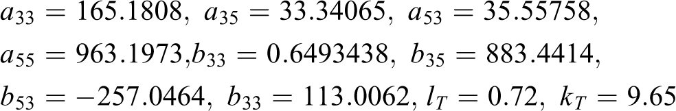
where ρ is water density, A is the T-foil area, v is the trimaran velocity, CL is the lift force coefficient, θ is the T-foil attack angle, xT is the distance of the T-foil pillar center to the trimaran gravity center, and kT is the slope of the lift force curve. kT is obtained by fitting the lift force data at different attack angles. Figure 11 shows the data point and the fitting curve. Then, the slope kT is solved and the value is 9.65.
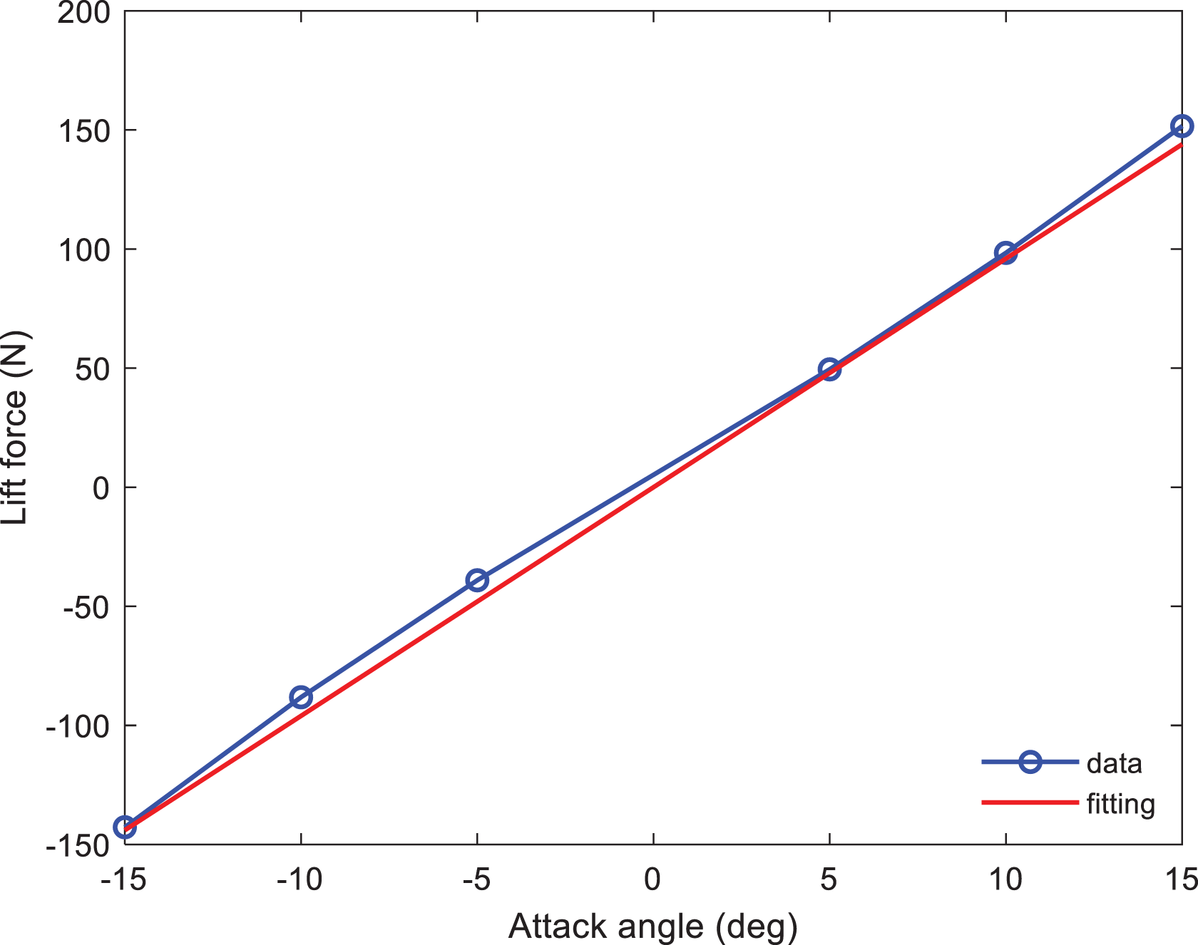
The lift force-fitting curve.
Disturbance observer and controller design
From equations (1) and (2), the heave and pitch motions of the trimaran are mainly caused by disturbance force and moment of waves. To improve the dynamic performance and robustness of the control system, the interference suppression is necessary. As a result, it is necessary to use a DOB to estimate the uncertainty disturbance in real time. The model of the disturbance control system can be approximately equivalent to the nominal model. Then, a model predictive controller based on DOB is designed to improve the antidisturbance performance of the control system.
Disturbance observer design
With the control force, equation (7) can be rewritten as the state space and shown as

where

After performing several simple mathematical manipulations, equation (10) is obtained as

The initial DOB is designed as

where
However, the designed observer is not implemented due to that the disturbance is unknown. The auxiliary variable z is induced, and the DOB is designed as

where
The MPC with DOB is shown in Figure 12. The DOB is used to eliminate external disturbances

MPC with disturbance observer. MPC: model predictive control.
The estimation error of the DOB is defined as


Then, the dynamic equation of the designed DOB is

The Lyapunov function is defined as

where
Derivative
There exists a positive number
Controller design
The control system of MPC with DOB is shown in Figure 13. Using a zero-order holder to discretize equation (9), the result is given by


Control system of the trimaran.
Equation (18) is regarded as a predictive model, and the following prediction states are obtained by the iteration

For convenience, some matrices are defined as

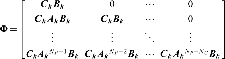

where NP
is the predictive step and NC
is the control step. Combining equation (18) and substituting

The disturbance matrix items

where
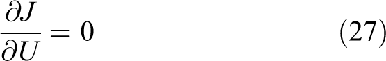
The necessary condition for minimizing the objective function is

The error of control system

The Lyapunov function is selected as

where e
1 is the estimated error of the designed DOB. Due to the matrix,

Derivative (23) and combining (24), equation (25) can be obtained as

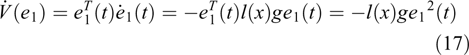
Then, equation (17) is shown as

It can be seen from the prediction objective function in equation (20) that to achieve the minimum performance index, it must be satisfied with
From equations (25) to (27), the result is obtained as

Then, the closed-loop system error asymptotically converges and the system is consistently stability.
Constraint handling
The range of T-foil attack angle is limited in actual manipulation. There exists a significant problem in the optimal control law obtained from the previous section. When the control quantity is higher than the constraints of actuator in long term, it damages the physical actuator. Consequently, it is necessary to limit the range of the attack angle of the T-foil during the control system design. When the predictive control step is Np , at the time k, the constraint of the attack angle control amount in the future step j can be expressed as

And, the vector forms are shown as

where

Equations (20) and (29) are organized to obtain the control problem with constraint conditions and written as
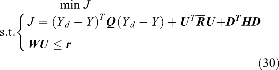
With
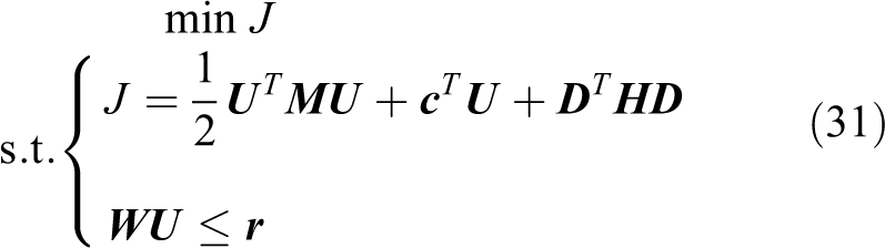
where
From equation (31), the original problem is converted to a quadratic programming problem. The Lagrange multiplier method and the effective set method in predictive control are used to deal with the constraint conditions. In this way, the inequality problem is converted to an equality constraint by adding a Lagrange multiplier vector, and the Lagrange function is given by

where
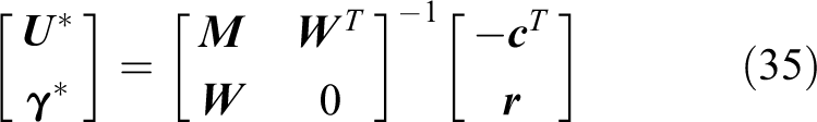
Then, Lx is partial derivative to U and γ, the matrix form is obtained as

The effective set method is used in the predictive control, the idea is: For any feasible solution

where wi
is the i’th row vector of the constraint set
The feasible solutions
To facilitate the iterations for predictive control, the feasible solution

At each iteration,

The Lagrange multiplier method is also derivative to δ and γ and the feasible solutions
Remark 1
When
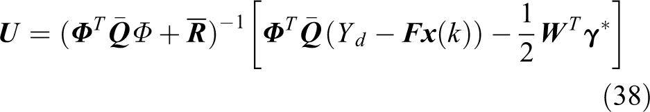
To improve the robustness of predictive control, a rolling horizon optimization strategy is adopted. The first item of the optimal control sequence is applied to the controlled object, such that the control law with the constraint condition is shown as

where
Remark 2
When
Remark 3
When
Remark 4
When
Summarizing the conditions discussed above: If a step size is
Simulation analysis
In the simulation, the random wave spectrum is used to simulate the irregular wave. 29 The sea state is 4 with the wave height range 1.25–2.5 m. As the trimaran model is a 1:23 model, the wave range is changed to 0.054–0.110 m and the heading wave is selected. Considering the trimaran under the condition of 40 knots, the above matrix parameters in “Trimaran motion equation” section, which can be calculated are
Using the determined weight matrix and prediction step size in the controller, a PID (Proportional, Integral, Differential) controller is used as a comparison. The simulation result is shown in Figure 14. Figure 14(a) and (b) shows the heave and pitch motion comparison, while Figure 14(c) and (d) shows the attack angle of the PID controller and the controller of MPC with DOB.

The control method comparison. (a) and (b) The heave comparison, (c) the attack angle changed in PID controller, (d) the attack angle changed in MPC + DOB controller. MPC: model predictive control; DOB: disturbance observer.
Conclusion
To reduce the heave and pitch motions of the trimaran, a T-foil is selected as the appendage and installed on the bottom of the trimaran. Then, the controller of MPC with DOB is designed to change the T-foil attack angle and perform the algorithm through simulation. As a comparison, the PID controller is performed at the same time. Through analyzing the result, the heave motion decreased by 56.73% and the pitch motion decreased by 42.15% using the controller of MPC with DOB, while the heave motion decreased by 32.75% and the pitch motion decreased by 34.26% using the PID controller. It is seen from Figure 14 that the MPC with DOB can greatly suppress the trimaran longitudinal motion.
Footnotes
Declaration of conflicting interests
The author(s) declared no potential conflicts of interest with respect to the research, authorship, and/or publication of this article.
Funding
The author(s) disclosed receipt of the following financial support for the research, authorship, and/or publication of this article: This work was supported by the National Natural Science Foundation of China [51379044] and the Fundamental Research Funds for the Central Universities [HEUCF0418].