
Abstract
This article presents Hecatonquiros, a complete open-source ecosystem for low cost and lightweight robotic manipulators. It has been released to focus on aerial manipulation applications but can be used in any other robotic application that requires the use of manipulators. The proposed framework provides the control system, a simulation environment, and a set of back ends to allow reusing the algorithms with different hardware setups. Additionally, it is released with a set of tools to ease its usage and various examples to teach the users. Several manipulators models and end-effectors are available for the users to adapt to their different requirements. All the hardware is designed to be three-dimensional printed and its components are low cost and available in common robotic stores, so anyone can reproduce and use them. The software is available in the GitHub repository https://github.com/Bardo91/hecatonquiros.
Introduction
The intention of this open-source software is to provide the community with a multipurpose, low cost, easy to build and use framework for robotic manipulation. This software was developed by the GRVC Robotics Lab at the University of Seville for Aerial Manipulation. For this reason, most of the hardware has been specially optimized to be used in aerial robots. Among all the specifications, the most critical is the weight. As aerial robots, or unmanned aerial vehicles (UAVs), have very strong payload restrictions.
The research about robotic arms for aerial manipulation has increased over the last years. 1 This rise comes from the need to operate in locations that are dangerous or difficult to access for human operators. In addition to increasing the safety of workers, the time to perform the manipulation and the costs are relevant motivations. This goal is achieved by making the robot to operate in those dangerous locations, and let the human employers higher level decisions tasks. The tasks, that robotic arms can perform in aerial manipulation, range from emergency tasks 2 to contact inspection 3 or assembly tasks.
Most of the research developed in this area has been performed in universities or research centers. It is difficult to find commercial or standardized manipulators to be used in these applications. Due to this fact, there is a need to develop tools that create a base to help researchers and companies to start building higher level solutions without needing to create the whole solution from scratch.
The concept of this open-source hardware is to release all the resources (software and hardware) to allow any user, developer, or researcher to use and modify it. This fact has great benefits. At first instance, it allows the users to customize the solution and to adapt it to their necessities. This is useful for companies, they could save costs in closed proprietary solutions. However, the changes performed by the users can be integrated into the core resource, improving it and helping all the users around the world.
Contributing to the code and being able to test an open-source software gives the opportunity to enhance and collaborate to obtain a better solution that everyone can use freely. Moreover, open-source projects usually use standard solutions and linkages. So that they do not create specific dependencies with closed proprietary solutions. Thus, they have more flexibility to be exported to new systems for multiple applications.
One example of open-source software is OpenRAVE. 4 It provides an environment to develop algorithms for planning and testing robotic arms in realistic environments. It is easy to integrate and focus on the analysis of the kinematics of the manipulators.
In relation to robotics open-source projects, one of the most well-known simulators is Gazebo. 5 This project is widely used in robotics because it is compatible with the Robot Operating System (ROS (http://www.ros.org/)). Furthermore, it can simulate a large number of sensors and robots to verify developers solutions before testing them into the real environment.
A fundamental part of the robotic arms is to model its kinematic. There are some libraries for this purpose. In Beeson and Ames, 6 various inverse kinematics (IK) algorithms are studied and integrated in the open-source Orocos Kinematics and Dynamics Library (KDL). Later, in the same article, a more efficient implementation than KDL’s only joint-limit-constrained IK is described, which is a pseudoinverse Jacobian IK solver. In Kumar et al., 7 the author makes an approach to solve the IK problem, transforming them into a nonlinear optimization.
The open-source software in robotics is not limited to libraries or robotic arms, it is possible to find them for humanoids. Metta et al. 8 propose a software and hardware platform that makes possible to use a functional humanoid robot ecosystem. It is focused more on research-level programming. In Edsinger-Gonzales and Weber, 9 the authors present a new force sensing and compliant humanoid, which allows exploring issues related to dexterous manipulation, visual perception, and learning. Finally, Brooks et al. 10 show an upper-torso humanoid robot. This half-humanoid has 21 degrees of freedom (DoFs) and a variety of sensors. It includes visual, auditory, vestibular, kinesthetic, and tactile sensors.
Most of the existing open-source software for robotic arms are programmed with Arduino. 11 This widely used platform has the advantage of being very simple. However, it has strict computational limitations. Another lack is that it does not offer the possibility to work in a simulation environment. Nevertheless, it is a quick solution for testing and designing.
Another disadvantage of current open-source projects of robotic arms is that they are intended to be used in fixed locations. 12 These existing projects propose heavy arms, which cannot be integrated in some robotic applications such as aerial manipulation.
Motivated to develop a more efficient, reliable, and powerful system, a complete system programmed in C++ and Python has been built, which will be presented in this article. Although the purpose of these robotic arms is to be used in aerial platforms, they can be reused in other fields.
The weight is a very important factor in aerial manipulation on UAV platforms. Moreover, it is important to know where to apply forces and torques in order to not destabilize the UAV. In Papachristos et al., 13 the authors develop a methodology for controlled forward thrust force and rotating moment exertion to guarantee a safe operation.
An important part of manipulators is their end-effectors. A large number of different open-source robotic hands can be found in the study by Zisimatos et al. 14 An example of gear-based gripper is shown in the study by Tlegenov et al. 15 Others use complex threaded systems to contract and extend the fingers. 16 However, these robotic hands are usually complex and have limited strength. For this reason, our manipulator designs are actuated with worm-screws, maximizing the strength of the grippers. Additionally, the whole hardware has been designed to be easily reproducible and are available for low budgets. All the parts can be three-dimensional (3-D) printed and assembled directly from the printer with just a few screws.
In addition, there is an end-effector plug and play system which permits the easy change of a variety of tools. Along with the end-effectors system, there is an effective detaching system to facilitate the assembly of the arm. Finally, both the end-effector system and the back-end system allow the adaptation of new tools. The implementation of software utilities, such as a graphical user interface (GUI) and the control of robotic arms through the use of a joystick controller, are also available in the developed system.
The proposed framework has the following objectives: Facilitate the application of manipulators, particularly aerial manipulation. Manipulator’s parts can be 3-D printed and easy to replace. All the hardware and electronic devices are low cost and available in the market. Provide an abstracted easy to use interface to allow both simulations and real applications. Give tools and examples for developers with any experience.
The remainder of the article is structured as follows. In the “Hardware” section, the mechanical design and electronic components for the manipulators are introduced. Additionally, a brief summary of the kinematic model is described. The “Software” section describes the code framework of the overall system. In the “Tools” section, the different tools that can be used are shown, with the corresponding libraries described. These have been released to provide a set of minimal tools to set up and use the manipulators. The “Applications” section shows some applications in which this framework has been used and the “Conclusions” section summarizes the implemented ecosystem highlighting the advantages of the proposed software and possible future developments.
Hardware
In this section, the available models of the robotic arms are introduced, as well as the end-effectors designed for different manipulation applications.
Manipulator’s core
Manipulators consist of two parts, the manipulator’s core and the end-effector. The core is a four DoFs manipulator that gives the main work volume. Then, at the fourth joint, a socket has been placed to allow to attach different end-effectors, such as grippers, or any other tools.
Two models of these manipulators have been developed. The first was designed using pulse width modulation servocontrollers. This model is shown in Figure 1(a).
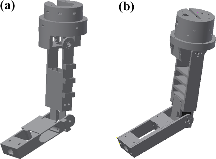
Models of robotics arms deployed with Hecatonquiros. (a) PWM arm and (b) smart serial servos arm.
The above type of servocontrollers is available in the market at a relatively low cost. However, it has the disadvantage of not providing any feedback from the real position. As usually, these have lower accuracy. Thus, they produce a mismatch between the expected position of the joints and the real ones. Nevertheless, the benefit of using this model is that the servocontrollers can be easily controlled by an Arduino board and both communication and control of the servocontrollers are easier.
The second model of the manipulator core can be seen in Figure 1(b). This model uses smart serial servocontrollers. These servos have a bidirectional communication system, allowing to command to the servocontroller and read from them. This makes possible to read the real angles of the joints, even if the target angles are not reachable. It is possible to know the real position of the end-effector and consequently the error to the expected position.
The PWM servocontroller is shown in Figure 2(a). The particular model used is a Turnigy TGY-S901D. Nevertheless, it has standard specifications, so there exist similar models from different providers that fit into the arms.

Servocontrollers used in Hecatonquiros. (a) TGY-S901D, (b) FT-SCS15, and (c) FT-SC009.
The above model is widely used, due to the double axis that it has. It balances the rotation forces exerted in the servocontroller. The characteristics can be found in Table 1.
Characteristics of PWM servocontroller.

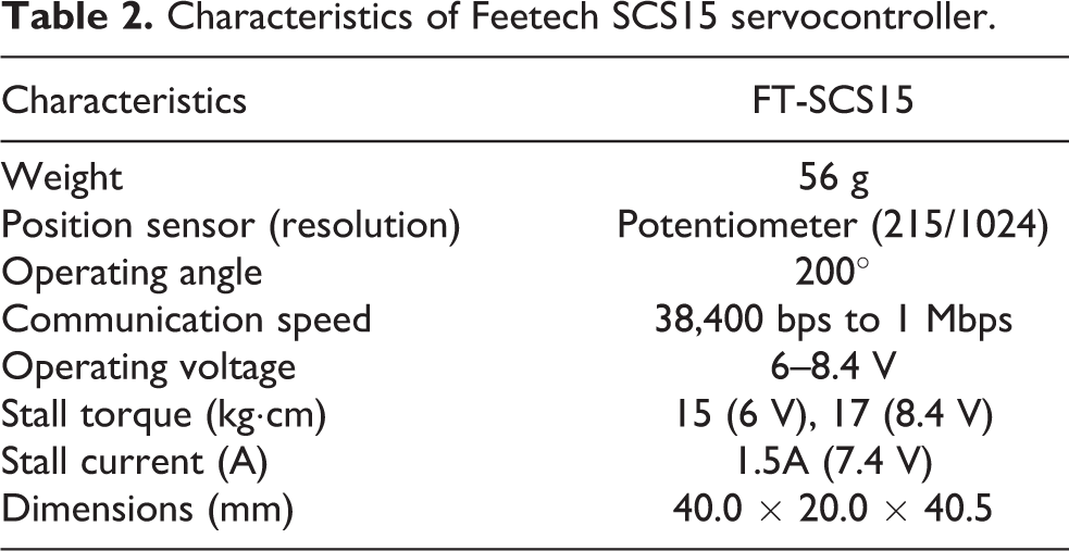
Figure 2(b) shows the smart serial servocontroller selected for the second manipulator core, a Feetech SCS15. As aforementioned, this brand of servocontrollers has a bidirectional bus communication based on serial port. This communication allows to send a command and also to read a position from the servocontroller, unlike the servocontrollers that are controlled with a PWM signal. The main characteristics are given in Table 2.
Characteristics of Feetech SCS15 servocontroller.
The key benefit of using this brand of servocontrollers is the bidirectional communication system using a serial port. It gives a greater precision and stability than the PWM method.
These also have a double axis which is important to balance the forces in the joint. Feetech SCS15 servocontrollers have a torque of 17 kg/cm. Moreover, they can be connected sequentially so, the wiring system gets simplified. Contrary, all the PWM servocontrollers need to be directly connected to the controller board. Thus, the wiring gets more complicated because all the cables are conducted from the controller to the joints.
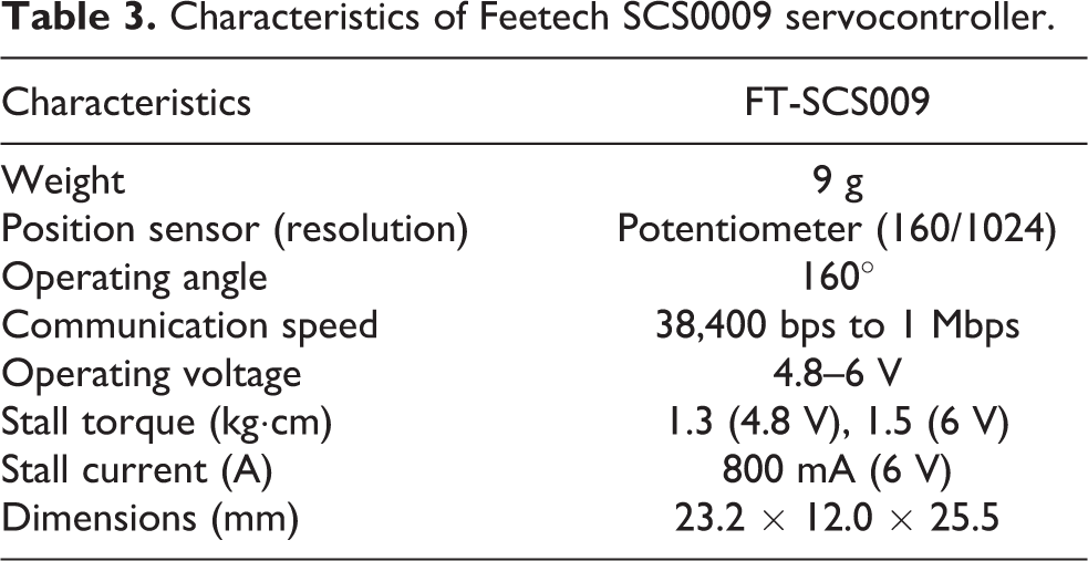
The last servocontroller introduced in this section is not used in the manipulation core but it is used in the end-effectors that will be described later. It is the Feetech SCS009 servocontroller which can be seen in Figure 2(c). The characteristics are summarized in Table 3. These servocontrollers have lower strength but are much lighter, making them perfectly suitable to reduce the weight in the end-effectors.
Characteristics of Feetech SCS0009 servocontroller.
Structural improvements
One of the principles of the proposed framework is to make it easy to fix and replace. All the pieces are designed to be 3-D printed. In the case of a part break, they can be replaced quickly by simply removing a pair of screws. Additionally, an special core has been placed in the design of the joints to make them resistant and light at the same time.
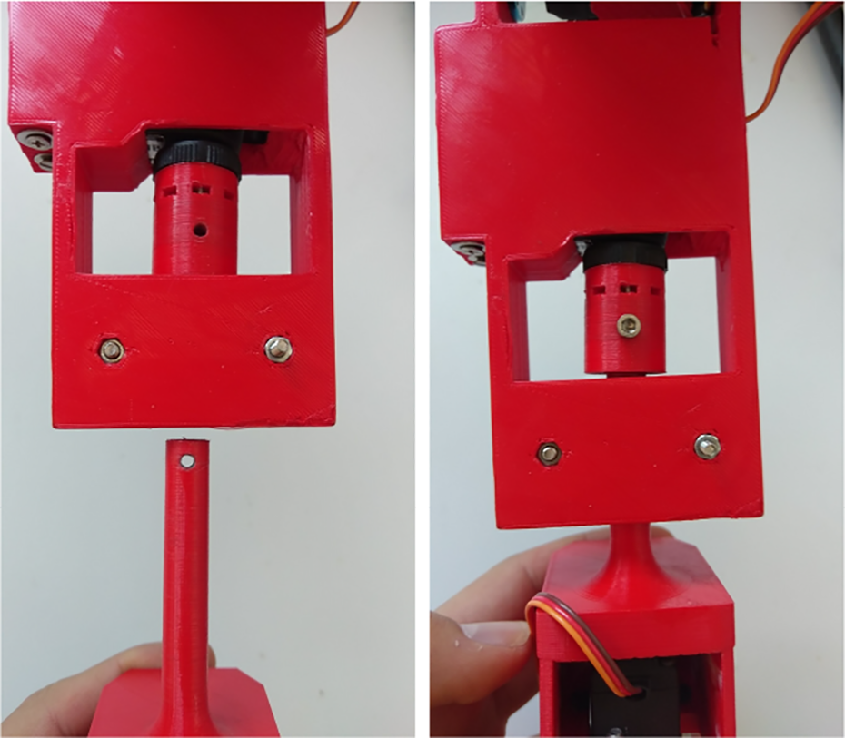
Concerning the structural design of the manipulator’s core, a self-structural holding mechanism has been designed at the first joint of the arm. As can be observed in Figure 3, the weight does not fall in the gear of the servocontroller. The whole weight of the structure is supported by the model, releasing the servocontroller of supporting that weight to reduce the friction, the surface is greased.

Self-holding structure mechanism for the first joint of the manipulator. Left picture shows the complete assembly of the structure. Right picture shows a slice of the structure in which it can be observed how the servocontroller do not suffer from the weight of the arm.
Additionally, two easy coupling systems have been developed to make the system more flexible and modular. The first system concerns the attachment of the complete manipulator to the robot structure. The second coupling system is the socket for the end-effectors.
The system that decouples the entire robotic arm of the UAV is in the first rotation and consists of a sliding system using a dovetail. This structure is shown in Figure 4.

Dovetail system for detaching the arms.
This system is designed without screws and to facilitate the assembly and replacement in the case that some arm breaks.
The second coupling system is placed at the end of the manipulator core. This coupling system, or socket, is designed for the tools or end-effectors. This system, as in the previous case, allows to quickly change the end-effectors without having to disassemble the complete robotic arm. It can be seen in Figure 5.
Coupling system for tools that connect on the wrist.
In this case, a simple screw is used to couple the end-effector to the joint. In addition, a pair of bearings, that can be seen in Figure 6, has been placed to add stability to the rotation. It is worth to mention that the servocontroller responsible for wrist’s rotation has been placed close to the elbow, reducing the torque and disturbances at the end of the manipulator.
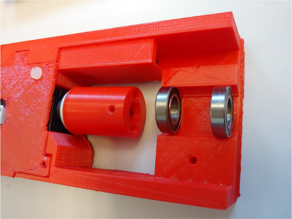
Wrist bearing system.
The whole set of the robotic arm, including the servocontrollers, weights 497.8 g. It is a fairly optimized weight, so can be placed in UAVs or small robot.
End-effectors
In addition to the design of the manipulator core, a set of end-effectors have been developed for different applications. These tools are independent of the robotic arm model used; that is, they are valid for the model with PWM servocontrollers and the model with smart serial servocontrollers.
All the grippers have been designed to be strong and resistant. Figure 7 shows the design. The actuator moves a worm-screw that transmits very efficiently the force to the gripper using a parallelogram mechanism. This system was chosen, due to the great force that it exerts to catch objects. Other systems such as gear-based claws are less strong and are more fragile when overloaded.

Real endless screw system.
The difference between the three grippers is that they can provide for extra DoFs. Figure 8(a) shows the simplest version with zero extra DoFs. Figure 8(b) shows the second gripper that provides the manipulator with an extra DoFs. At last, Figure 8(c) the most complex gripper which adds two DoFs to the manipulator.

Three different end-effectors shipped with Hecatonquiros. These are strong grippers that use a worm-screw to guarantee high gripping forces. Moreover, they can provide for additional DoF. (a) 0 DoFs, (b) 1 DoFs, and (c) 2 DoFs. DoF: degree of freedom.
The last tool requires special consideration. The details of this tool are in the study by Ramon Soria et al. 17 The main purpose is to provide the UAV for a relative localization system to control it at a certain position while performing an inspection or maintenance task. As the rest of the components, it has been designed to be lightweight. The complete model can be seen in Figure 9.

Model of docking tool.
This tool is composed of five passive joints. Each of them has an embedded potentiometer that provides a value that is mapped at an angle. This angle is obtained knowing the maximum and minimum that the potentiometer provides for a certain voltage, and, with a proper calibration, is transformed to angles. With these angles, and by defining the direct kinematics of the mechanism, the position of the robot is computed.
As the joints are passive, and it is important not to exert forces on the UAV, an efficient wiring system was designed. That allows to put the cables inside the joints as shown in Figure 10. These wires connect the potentiometers with the control board where their values are read. This wiring system has been designed so that they do not have any force in the joints.
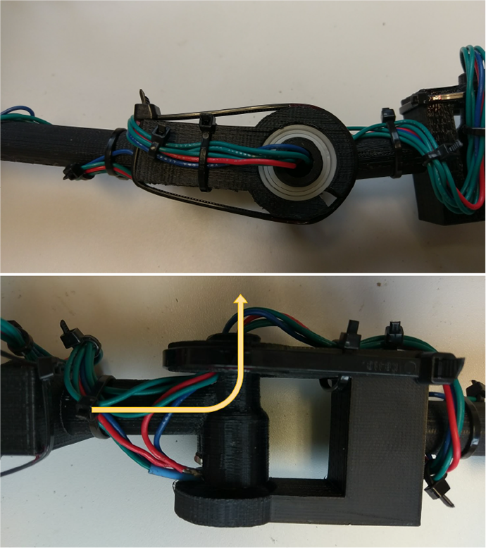
Docking tool wiring system.
Kinematic model
The kinematic model of the manipulator has been studied using the Denavit–Hartenberg method. 18,19 This method allows determining the direct kinematic of the system easily by the concatenation of the transforms. With this model, the volume workspace is defined and it can be observed in Figure 11.

Kinematic reachability of the robotic arm with the gripper of 2 DoFs. DoF: degree of freedom.
In order to move and control the arms, it is also necessary to describe the IK problem. Taking into account the multiple solutions and the mathematical difficulty to clear the unknowns by the high number of DoFs, two methods have been implemented.
The first method is given by OpenRAVE. 4 This method is suitable for checking the feasibility of a pose, but not for generating the right trajectory from the start position. With that purpose, a Jacobian damped-least square (DLS) algorithm has been implemented. The Jacobian matrix can be used to approximate these functions linearly.
DLS method has a greater convergence to the desired position and greater stability contrary to basic reverse Jacobian and pseudoinverse methods. To obtain the desired position, the DLS uses the Functions 1 and 2 at each instant to subsequently use the Function 3 and ensure that it moves to the desired position


Xk
and Qk
are the desired position and orientation at the moment k, while
Software: Controllers and tools
The software developed in this article is available in the GitHub repository (https://github.com/Bardo91/hecatonquiros). The general scheme of the system consists of several modules that can be found in Figure 12. This scheme shows all the available modules and the interaction between them. It is worth to mention that the system has full compatibility with the ROS ecosystem, so it is compatible with any application in this framework.
Overall system architecture.
Back ends
The system of back ends, shown in Figure 13, allows using the robotic arms in different ways. You can choose from the direct use of, for example, the serial port or using the ROS system. Additionally, this can be used in simulations. To debug the use of robotic arms in multiple situations, without having to try out them physically.

Scheme of back ends.
The system is designed so anyone can create a new back end in a simple way. So people are not forced to use just the existing. They can implement a new back end for a new type of servo motors.
Currently, there are three back ends implemented: Arduino: Making use of the serial port through this back end. It allows to communicate with an Arduino board. The working scheme of this back end can be seen in Figure 13. Once there, through a simple reception module, it can use PWM servocontrollers connected to the output pins of the Arduino board. This back end encompasses all the use of PWM servocontrollers, which are cheaper, but less precise and stable. Feetech: Like the previous back end, the serial port is used to communicate with the servocontrollers. In this case, the servocontrollers are controlled through the serial port using predefined commands.
These servocontrollers provide feedback of the position, torque, and even the power consumed. In addition, they are more accurate than the PWM servocontrollers. The final position will be more similar to the one calculated by the kinematic model.
In order to increase the speed of the serial port communication, a new back-end system was created when two robotic arms act are used. This new back end hacks the scheme as shown in Figure 13. It is formed by a queue that handles the communication between multiple servocontrollers. All this using threads and mutex so the actions are not blocking. An outline of this specific back end is shown in Figure 14.

Scheme of the Feetech queue thread back end.
It is necessary to comment, that the function of reading the positions of the joints, is waiting for a condition variable that the queue thread provides to return the values read from the requested joints.
ROS: This back end uses ROS topics to send the desired position or joints which the robotic arm will go. Also, there is an option to receive valuable information, such as the position of the servo, among other topics. It can be used to communicate with Gazebo too. As in the previous back ends, the scheme is shown in Figure 13.
Model solvers
Model solvers are in charge of computing the value of servocontrollers joints using the IK and, through direct kinematics, moving the robotic arm to the desired position.
Depending on how complex the robotic arm is, there are different solvers similarly to the back ends. The framework has been designed in such a way that more can be added, in a very simple way.
Simple 4 DoF
It is a particular development to solve the direct and IK of manipulator’s core with four DoFs. Given the rotation axis position, different solutions for the same point can be obtained. As in the case in a robotic arm, when at one point the elbow has two possible solutions The main advantage of this model solver is that it allows having the desired position with very little computational cost and greater speed. Although its fundamental disadvantage is that it only serves for the robotic arm of 4 DoFs.
OpenRAVE
This part is centered in solver the IK and in the next section, we will see the part of the simulation. OpenRAVE gives a simulation environment, in addition to providing the IK of the robotic arm model that they have put into the system. 4 This environment check the kinematic reachability of the robotic arm and generate a smooth trajectory if it is possible. This solver model provides the most accurate solution. However, it produces a greater computational expense and therefore a greater slowness when obtaining the solution.
ROS
This model is intended to be used with ROS compatible robots and simulations. With this model solver, there is the option of making use of position, transformations, and joints topics to obtain from them the information necessary to calculate the kinematics. Its main advantage is to allow obtaining the information provided by another system that uses ROS. However, it is necessary to use another module that provides the IK to receive the desired position.
Tools
This section describes a set of tools that provide, with simple use, a GUI, a joystick to control the robotic arms, and the visualization of a simulated environment for testing. Additionally to this core of tools, others are designed to give extra functionality for the robotic arms.
OpenRAVE simulation environment wrapper
As discussed in the previous section, OpenRAVE is a library already created that enhances the use in simulation of robotic arms. It provides a simulation environment that allows testing the algorithms. Specific positions are able to put objects and interact with them. Doing simulations of grasping before performing them in a real environment is essential to prevent accidents. All this integration is done in a simple way, so the user does not have to learn to use the OpenRAVE library.
In Figure 15, it can be seen the robotic arm system in the OpenRAVE simulation environment. There are different cases in which the robotic arms act to catch different objects such as a mobile robot, pipes, and even a car steering wheel. Following with examples of the simulation system, Figure 16 shows different positions of the arms at the time of picking up the mobile robot. These simulations are a great value because they can detect failures before performing a real tests with the complete system.

Examples of robotic arms acting with different objects.
Different positions of robotic arms.
Gamepad controller
The framework also provides for a manual control architecture. There are two options implemented in the core library. The first option is to use a gamepad or joystick controller. In this mode, it is possible to perform remote teleoperation. The functionalities range from the opening and closing of the claws to the possibility to move a single manipulator independently or directly the pair of arms making use of each joystick.
Graphical user interface
The second option to manually operate with the manipulators is by the use of the graphical interface shown in Figure 17. There are different options such as moving the arms to the desired point, moving the arms with desired joints, and the possibility of receiving the position of the arms or moving them in small steps on any corresponding axis. It is possible to actuate on the end-effectors, for example, opening and closing the grippers.

GUI to control robotic arms. GUI: graphical user interface.
Display applications
Apart from the visualization of the robotic arms simulation, a set of applications have been created to visualize in a plot, the positions of the joints of each robotic arm. These applications provide for an accurate view of the data. The user can see if the servocontrollers reach the desired position, thus being able to verify the operation of the system.
Calibration applications
To facilitate the installation of the servocontrollers in each robotic arm, a calibration system is provided. This tool is used to map the maximum and minimum values of the joints at specific angles. These values will be used in the back ends to map and send to each servocontroller to the correct position. This system is also used to calibrate the docking tool, being an effective calibration tool and reusable for both systems.
Applications—Use cases
This open-source project has already been used in applications with UAVs. Most of them under the framework of the EU-funded project.
The first platform in which this project has been used is shown in Figure 18. It consists of a hexacopter based in the F550 frame with a single arm embedded at the bottom. This work was presented in Ramon Soria et al. 20 and showed various results of grasping objects using a stereo camera and the PWM manipulator core presented in the “Hardware” section.

Aerial robot with single manipulator.
This first start-up of the system was useful to find the failures to improve it in terms of precision, speed, and strength. Also, with a single robotic arm, there are limited capacities when interacting with the environment.
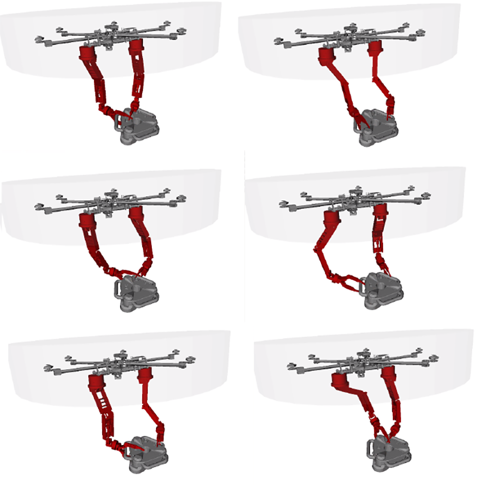
The second aerial robot that uses this framework is as shown in Figure 19. This platform presents improvement with respect to the previous one. It has two manipulators embedded at the bottom and the landing gear is foldable.

UAV on the ground with the two robotic arms with the gripper tool. UAV: unmanned aerial vehicle.
With this platform, it was intended to show how the framework is able to handle multiple manipulators at the same time in the aerial platform to perform more complex and dexterous manipulation tasks. This improvement is pretty important, as having two manipulators, increase the stability of the manipulation tasks and even increase the range of operation that the robot can perform.
Some examples result in different environments are shown in Figure 20.
Gripper tool test system in real environment.
The flexibility of the system allows to use it in a real environment and, at the same time, see the results in the OpenRAVE simulation as it can be seen in Figure 21. This digital twin allows to evaluate the performance of the system against the ideal operation.

Bench test of the complete system.
The possibility of having a test bench where to test the system created before doing it in the real environment provides a feedback on how to improve it before using it and to verify its correct functioning.
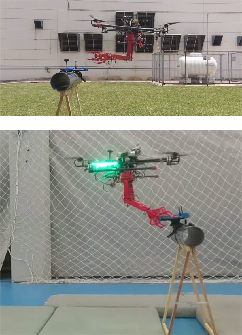
Finally, the last application developed using this framework is the contact position estimation using the docking tool presented in the “Hardware” section. This tool is used to keep in contact with an attaching point while operating close to it. The tool provides for an estimation of the robot’s position which is used to close the control loop of the UAV.
To obtain all the information mentioned above, a C++ and a Python interface have been implemented, which use communication through the serial port to a controller board and provides the values read from the potentiometers. Two examples of operations are shown in Figure 22.

Test of the docking tool system in real environment.
In the top figure, it can be observed a normal operation with the docking tool. The position information acquired by the device is used to close the position control loop of the aerial platform. In the bottom figures, it can be seen how this information is used to control the position of the end-effector of the right manipulator too. This tool is quite useful to obtain this local position estimation it is fast and does not have any computational cost compared to other computer vision algorithms.
Conclusions
The work presented in this article shows a complete hardware and software system to build, use, and control robotic arms. This system can be used for any robotic application, but it is particularly designed to be applied in aerial manipulation tasks.
The use of robotic arms in aerial manipulation applications has been validated in real environments for grasping with different grippers. Furthermore, the use of other tools, such as the docking tool, demonstrates the ability to adapt the robotic arms to any end-effector.
The system can be used autonomously. Additionally, the operators can provide commands by means of a GUI or through a joystick controller.
The system can be simulated before using it in a real environment. It is fully compatible with ROS and Gazebo. In addition, a simulation environment using the OpenRAVE library is available minimizing the required previous knowledge of users.
Future work related to this research will focus on continuing with the design thus improving its performance, creating new robotic arms of different sizes with better servocontrollers. Therefore more back ends and model solvers will be needed. It is also considered the creation of a new manual control system, modeling the human skeleton to move the robotic arms in a more intuitive way.
Footnotes
Acknowledgement
The authors thank Robotics, Vision and Control Group for supporting them during this work.
Declaration of conflicting interests
The author(s) declared no potential conflicts of interest with respect to the research, authorship, and/or publication of this article.
Funding
The author(s) disclosed receipt of the following financial support for the research, authorship, and/or publication of this article: This work has been developed under the framework of the projects AEROARMS (SI-1439/2015) EU-funded project and the Spanish national project ARM-EXTENDED (DPI2017-89790-R).