
Abstract
This article presents a software layer to abstract users of unmanned aerial vehicles from the specific hardware of the platform and the autopilot interfaces. The main objective of our unmanned aerial vehicle abstraction layer (UAL) is to simplify the development and testing of higher-level algorithms in aerial robotics by trying to standardize and simplify the interfaces with the unmanned aerial vehicles. Unmanned aerial vehicle abstraction layer supports operation with PX4 and DJI autopilots (among others), which are current leading manufacturers. Besides, unmanned aerial vehicle abstraction layer can work seamlessly with simulated or real platforms and it provides calls to issue standard commands such as taking off, landing or pose, and velocity controls. Even though unmanned aerial vehicle abstraction layer is under continuous development, a stable version is available for public use. We showcase the use of unmanned aerial vehicle abstraction layer with a set of applications coming from several European research projects, where different academic and industrial entities have adopted unmanned aerial vehicle abstraction layer as a common development framework.
Introduction
In the last few years, there has been an outstanding increase in the number of applications for unmanned aerial vehicles (UAVs). 1 Their current levels of autonomy and cognition make them suitable to perform many different tasks, which are usually implemented by high-level algorithms. UAV technology is advancing fast, and hence, there is a wide spectrum of platforms and autopilots (i.e. on-board software for basic operation) available for the community. This variability is also due to the specific constraints associated with each application. Platforms with different payload capacity, maneuverability, or autopilot functionalities may be required depending on the context. Nonetheless, high-level algorithms should be able to operate UAVs in a transparent manner, regardless of the autopilot or platform underneath. Otherwise, it would become too complex maintaining multiple versions of the application software depending on the particular communication protocols for each autopilot.
Several frameworks for UAV operation, both proprietary and open-source, have been developed over the past years. 2 Moreover, some open-source organizations like Dronecode (https://www.dronecode.org/) have proposed standard communication protocols for UAVs, as for instance MAVLink. 3 However, despite the increasing use of this protocol, there are still many autopilots that do not support it. For example, the industrial leader in UAV manufacturing DJI (https://www.dji.com/) works with its own proprietary autopilot framework. There are also more elaborate and complex frameworks to deal with teams of multiple aerial 4 or heterogeneous 5 robots, or to propose complete solutions including the hardware platform. 6 However, our focus is more on abstracting the autopilot to make easier the development of higher-level algorithms, that is, algorithms that operate with the UAVs in a transparent manner.
Royo et al. 7 proposed a service abstraction layer to ease application development with UAVs. This is a big and complex architecture to cope with every possible application and functionality related to a UAV. Inside this complex architecture, they proposed a virtual autopilot system 8 that tried to abstract and standardize the autopilot interface. However, there is no publicly available implementation of this work. On the other hand, we propose a simple layer in the framework of the robot operating system (ROS) 9 which is public, open-source, ready to use, and easy to expand to other autopilots.
Additionally, it is essential to integrate the UAV software frameworks with simulation environments in order to switch from simulated to real platforms with minor efforts. Due to the fact that UAVs are more sensitive and fragile than common ground vehicles, preliminary simulations to verify the correct operation of the whole system become even more critical. For that, there are widespread simulators, such as Gazebo, 10 V-REP, 11 or AirSim, 12 that allow researchers to test UAV and multi-UAV systems, for task allocation 13 or path planning algorithms, 14 among others. MATLAB Simulink has also been proposed as a rapid prototyping environment for UAVs. 15 Simulators with realistic 3-D engines (e.g. AirSim) can also be used for testing computer vision algorithms.
In this article, we introduce our software framework for UAV operation, which provides users with an abstract interface independent of the autopilot. First, we describe a relevant set of functionalities that every UAV should implement. From this set, we define a common interface that we call unmanned aerial vehicle abstraction layer (UAL). Then, for each supported autopilot, a back end dealing with its specific features must be created. Our framework aims to ease the development pipeline of UAV algorithms and their deployment into real platforms.
The main contribution of the article is to explain the design of our UAL and the details of its implementation, which is publicly available. 16 We also describe how our UAL provides a simple way to simulate multiple UAVs and how its interfaces make use of real or simulated robots transparent to the user. The current implementation addresses mainly multi-rotor platforms, but it is general enough to be extended to fixed-wing vehicles. Finally, we showcase the usability and versatility of our framework by means of several use cases. In particular, our UAL has been in a continuous development process for more than 2 years and it has been successfully tested in multiple experiments within the context of different European R&D projects. For each use case, the context of the project is explained as well as how UAL is used to integrate UAVs into high-level missions.
The remainder of the article is structured as follows. The second section details the architecture of our UAL and its core functionalities; the third section describes simulation functionalities; the fourth section discusses valuable lessons learned during our field tests with UAL; the fifth section shows use cases on the use of UAL for research projects; and the last section provides conclusions and future work.
UAL architecture and implementation
This section describes the design and implementation of the main features of our UAL. For more details, a thorough wiki with instructions for installation and use is available online (https://github.com/grvcTeam/grvc-ual/wiki).
Preliminaries
Even though their implementation details may vary drastically, all autopilots share similar functionalities. First, they are all meant to provide some level of autonomous flight. To achieve that, they typically implement a cascade of modules for estimating and controlling angle rate, angle, velocity, and position. Some autopilots accept external references in any of the controllers, but the most common and useful controls for high-level users are velocity, position, and yaw controls. Another common concept for autopilots is the flight mode. Depending on the current state, the task that is being executed, or the set of controllers that are handling the flight, the autopilot declares to be in a defined flight mode. Typically, each mode provides some level of control to the radio control (RC) human pilot (the so-called safety pilot), and at least one of them allows for autonomous control from an external computer. We generalize and refer to the first set as manual modes, and the last one as auto mode. Moreover, in order to provide complete autonomous flights, autopilots usually implement additional basic maneuvers, such as takeoff and landing.
UAL tries to abstract the user-programmer from the platform’s autopilot. With that in mind, we defined a common interface with a collection of the most used UAV functionalities: Performing a takeoff maneuver to a given height. Going from current position to a specified waypoint in geographical (or any other global) coordinates with a specified yaw. Setting linear velocities and yaw rate. Landing on the current position. Recovering from manual flight mode. Setting home position to the current position. Getting latest UAV pose estimation. Getting latest UAV velocity estimation. Getting latest UAV coordinate transform estimations.
UAL builds on top of the widespread ROS, 9 which provides libraries and tools to help software developers to create robot applications. It provides hardware abstraction, sensor drivers, dedicated libraries, visualizers, message-passing communication, package management, and so on. The main advantages of using ROS are their extended use among the community and the fact that the communication between different processes and machines is easily solved. In particular, UAL has been developed and tested on ROS Kinetic Kame, even though it could be used with other versions with minor adaptation.
Core functionalities
The proposed framework consists of three basic layers (see Figure 1). The first layer is the UAL itself and it is implemented in C++ language. The second layer is the Back-end class, which establishes a common interface to the UAL and it is also implemented in C++. Last, in order to support each particular autopilot, a specifically derived back end for that autopilot must be implemented in C++. This back end communicates with the autopilot and handles specific details, offering a common interface on the user side. For instance, any autopilot that uses MAVLink as communication protocol (e.g. PX4 and ArduPilot) is currently supported via our MAVROS back end. The MAVROS back end communicates via MAVROS with the autopilot and handles specific issues such as mode switching and pose reference smoothing.UAL offers a double interface (see Figure 2) to be accessed by external users: Class: the developer can instantiate an object of the class UAL and access data and functionalities via its class interface, directly calling its member functions. Server: at the same time, inside the instance of the class and in a separate thread, UAL can be continuously publishing data and responding to service calls as any other node inside the ROS network.

Scheme with the different layers to implement the back ends in UAL. UAL and back-end layers are common, while derived back end is autopilot/protocol specific. UAL: unmanned aerial vehicle abstraction layer.

UAL offers a double interface with the user, either as a class or as an ROS server responding to requests. UAL: unmanned aerial vehicle abstraction layer; ROS: robot operating system.
While the class interface is middleware independent, it is always available and introduces no delay; the server interface depends on middleware (ROS in our case) is available only if server mode is enabled (it is by default) and may introduce network delays. Moreover, only one process can have one (and only one) class interface for a certain UAV. This may be an issue to handle multiple robots. However, the server interface can be reached from any host in the network and has been successfully tested with multiple UAVs.
The two interfaces are not exclusive in design nor in implementation (every function in UAL interface is thread-safe), and it might be convenient to use both of them, profiting from the advantages of each one. For example, delay-sensitive functionalities like velocity control are better suited to the class interface, whereas it is more useful to call the
We ran a simple benchmark experiment to evaluate the effect of the extra communication layer introduced by the UAL server interface with respect to the class interface. We set up a single computer running UAL with the MAVROS back end. On one side, a process commanded messages with a constant velocity and a timestamp using one of the two UAL interfaces. On the other side, another process reads actively (with no sleep) those velocity messages from the MAVROS topic
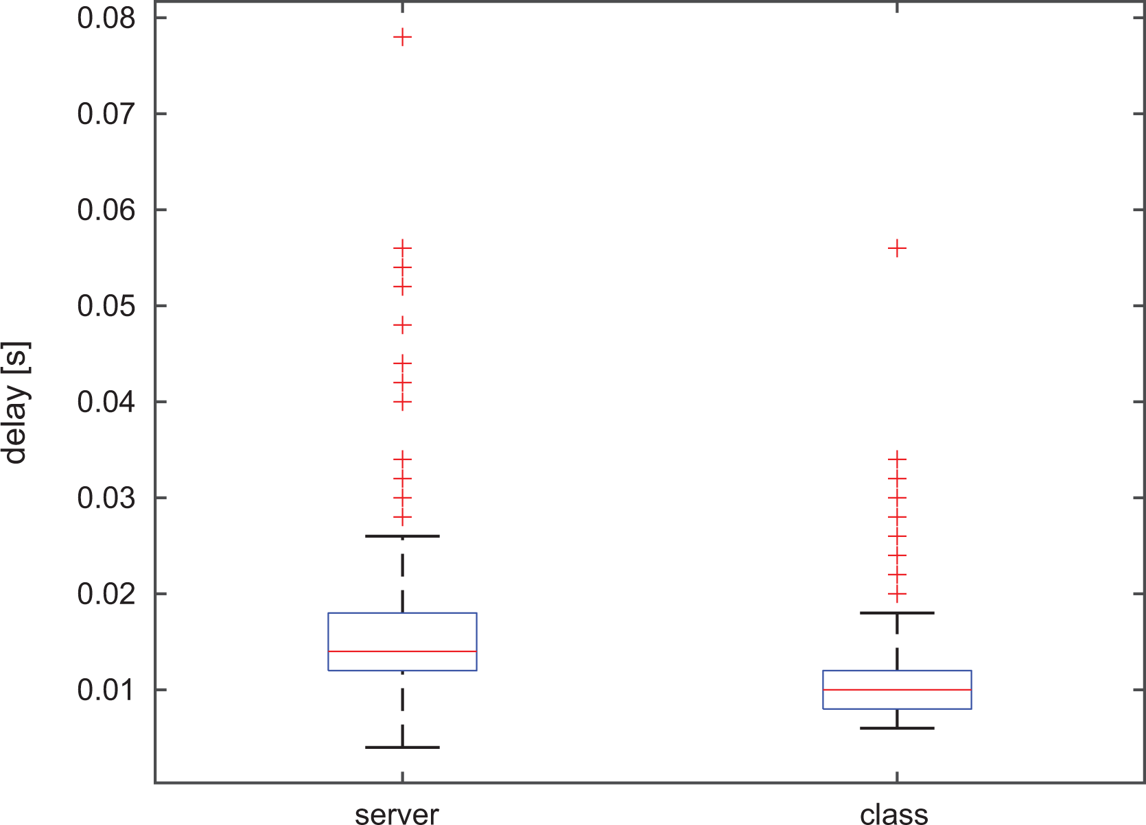
Results of benchmark experiment to compare time performance for the class and service UAL interfaces. Median values are indicated in red within blue boxes delimited by the 25th and 75th percentiles. The whiskers represent the extreme values and the red crosses outliers. UAL: unmanned aerial vehicle abstraction layer.
We implemented several back ends for UAL (see Figure 4), but the project is alive and our software layer is designed so that other users from the robotics community could easily create their own back ends. Currently, the main back end is for MAVROS (the ROS adaptation of MAVLink protocol), which is a widely spread protocol for communication with autopilots. Some well-known autopilots such as PX4 and ArduPilot support it. The MAVROS back end together with PX4 is the most tested combination of UAL so far, and it supports both the last MAVROS version and older versions. We recently enhanced it by adding a back end interfacing directly with MAVLink without using MAVROS. The second main back end is the one using the ROS SDK from DJI. This one allows us to communicate with DJI proprietary autopilots such as A3 or N3. The Light back end is used to provide support for simple simulation and the unreal engine (UE) back end supports simulation through the UE. They both will be detailed in the next section about simulation functionalities. There is also a back end to support the Crazyflie miniature quadcopters (https://www.bitcraze.io/crazyflie-2-1/). Finally, the Custom back end is under development and interfaces with our own autopilot. We are developing our custom autopilot in order to have the possibility of modify the internal controllers easily.
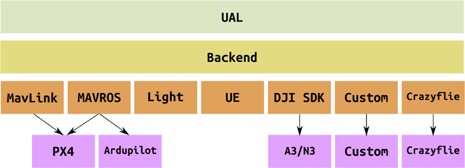
Scheme with the existing back ends for UAL. Each implemented back end can communicate with different autopilots using the same protocol. Additional back ends can be added easily to extend UAL reachability. UAL: unmanned aerial vehicle abstraction layer.
Coordinate frames
As many other ROS applications, UAL also publishes coordinate frames or TFs. We treat UAL as the interface with the robot (UAV in this case) so it publishes
The TF
UAL is prepared to be used with multiple UAVs simultaneously, so these frames are automatically adapted to the corresponding namespace. Figure 5 shows the result of running the ROS command
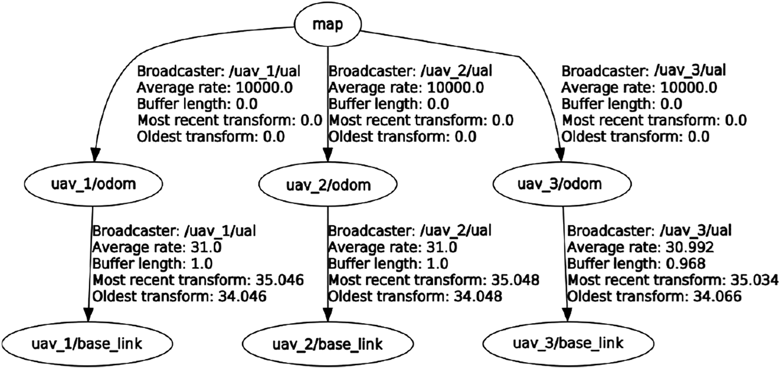
Screenshot of the output of the ROS command
Teleoperation
A UAV can be teleoperated, that is, manually controlled through UAL (RC control is reserved to the safety pilot). The teleoperation package, called Keyboard: The user is guided through a simple console menu that enables her/him to take off, land, and control the UAV in pose or velocity. In pose and velocity control, a set of joystick axes are emulated through arrow keys and w/a/s/d keys in order to allow for smooth control of movements in every direction. Arrows are used for forward, backward, and sideways movements, whereas w/a/s/d keys control altitude and yaw. Joystick: Through a combination of buttons and axes of any ROS supported joystick, the user can take off, land, and control the UAV in velocity. It is also possible to change maximum speed and enter in headless mode, where the UAV velocity is commanded in a ground fixed frame (ENU), regardless of UAV current orientation (yaw).
In the keyboard case, the used keys and their meaning are fixed, but there are many possible joystick devices that have different axes/buttons layouts and are mapped differently by the ROS joystick package. To achieve a more coherent joystick use, we have developed a two-step solution. First, any joystick must be translated to a standard layout. In our case, the standard of 6 axes and 12 buttons is inspired by the RetroPad from the RetroArch project (https://github.com/RetroPie/RetroPie-Setup/wiki/RetroArch-Configuration). Axes and buttons layout are shown in Figure 6. By means of a configuration process, any joystick can be mapped to this standard joystick layout. Second, another configuration is used to map desired user actions to the standard joystick layout. This allows us to refer in the code to axes and buttons by the action they trigger instead of by the label in the joystick layout. In case a given joystick does not have a button that was initially mapped to some function, only the configuration file has to be modified, not the actual code.

Layout for a standard joystick. Top: 6 axes used; bottom: 12 buttons used.
These joystick functionalities are implemented in an independent module, so they can be used by other software packages, being the second configuration step optional.
Simulation functionalities
In addition to the main advantage of abstracting users from the autopilot, UAL also provides tools that help users to easily test their algorithms in simulation. In particular, UAL is totally integrated with the well-known open-source robot simulator Gazebo (http://gazebosim.org). This simulator allows for fast robot prototyping and creation of new scenarios, and it is already integrated within ROS. Besides, we have recently integrated UAL with the UE (https://www.unrealengine.com) and its plugin AirSim 12 for UAV simulation. Finally, we have also successfully tested the DJI SDK back end with the DJI hardware-in-the-loop (HITL) simulation tools.
Integration with Gazebo
UAL comes with two possibilities for simulation in Gazebo: a light simulation and the PX4 software-in-the-loop (SITL) simulation. The first one uses a Light back end that provides a simple model of the UAV, avoiding dynamics, and draws the simulated UAV in Gazebo. This is particularly useful to perform simulations with large numbers of UAVs, where the focus is on high-level behavior and not on having realistic dynamics for the UAVs, which may entail computational issues.
The second simulation option is based on the PX4 firmware, 17 which is an open-source autopilot software. Along with the usual autopilot functionalities, PX4 firmware comes with an SITL simulation environment based on Gazebo and RotorS. 18 This SITL has several Gazebo plugins that simulate sensors (e.g. IMU, GPS, etc.) and dynamics (e.g. rotor velocities and forces) of the UAV. UAL comes with the possibility to run SITL simulations with the PX4 SITL, using the MAVROS back end. This feature allows users to run in simulation the same software as in the real platform, replicating low-level behaviors of the autopilot (such as waypoint transformations and mode switching) in a more realistic fashion.
Apart from the above options, UAL provides some scripts to launch quite easily simulations with multiple UAVs. It also provides different UAV models, included in an ROS package called
Integration with UE
Gazebo simulator is quite extended in the robotics community for UAV simulation. However, it lacks for a realistic graphics engine, which can be essential for testing computer vision and machine learning algorithms. Therefore, we have also enhanced UAL with a back end that provides an interface to simulate in realistic environments using UE. 19 UE is a game engine with a long tradition in the world of computer games. Its source code is publicly available and written in C++, which eases integration with UAL. Recently, Microsoft published AirSim, 20 which is a plugin for UE so that users can simulate robots. Figure 7 shows the modules involved and their interactions to integrate UAL with UE.

Interaction diagram between modules required for UAL integration with UE. UAL: unmanned aerial vehicle abstraction layer; UE: unreal engine.
With this enhancement, UAL is also able to provide more realistic simulations to test computer vision algorithms. Thanks to the powerful rendering engine of UE, it is possible to acquire high-quality footage that can be used online to feed those algorithms. Figure 8 shows three example platforms that have been tested in simulation via UAL.
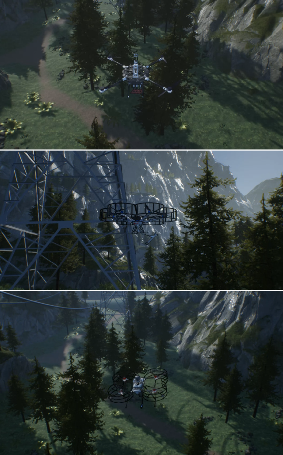
Realistic simulation using UE in a mountainous environment. UE: unreal engine.
UAL back end for UE includes an interface for the AirSim UE plugin, enabling UAV control in a similar manner as it does with Gazebo. Additionally, since some of our integrated UAVs have manipulators, UAL’s basic interface has been extended to control the aerial manipulators too.
Even though we enhance remarkably the visual realism of the simulations with UE, the downside is that it also increases the rendering time with respect to Gazebo. In principle, this higher computational load may jeopardize simulations when keeping up with real-time constraints. Nevertheless, UE is a professional framework that is extremely optimized, making it versatile and adaptable to the existing hardware.
In fact, we ran some tests with standard desktop computers to verify that simulations with UE integrated into UAL can hold with reasonable rendering times. Table 1 summarizes the average frequency update with different hardware configurations. The update rate of the physics engine remains stable independently of the computer, whereas the rendering engine speed, though always slower, increases notably with the power of the GPU.
Average frequency (Hz) of the physics and rendering engines in UE with three different GPUs.a

UE: unreal engine.
a All of them used an Intel i7 CPU.
Integration with DJI HITL
The UAV manufacturer DJI provides a set of tools that enable HITL simulation for their proprietary autopilots. In the development of the DJI SDK back end for UAL, these tools have been intensively used for testing before flying real platforms with our abstraction software.
In Figure 9, the setup required for the DJI HITL simulation and its integration with UAL are depicted. It involves three different major components: A computer running the DJI simulation software, currently available only for Windows and OS X. It simulates sensors and actuators within a simple empty simulated world, and it communicates with the autopilot as if they were real. A DJI autopilot hardware running the DJI autopilot firmware (currently the A3 and N3 models are compatible with HITL). These are exactly the same hardware and software that would fly on the real platform. A computer running UAL and its DJI SDK back end, currently only available for Linux-based operating systems.

Interaction diagram between modules required for UAL integration with the DJI HITL. UAL: unmanned aerial vehicle abstraction layer; HITL: hardware-in-the-loop.
This setup has two advantages. First, it uses the real autopilot hardware, so simulation is closer to reality. Second, it moves the often computationally heavy simulation, from the computer running UAL to a dedicated computer. However, these features come at the high cost; three pieces of hardware are required for a single UAV simulation. This is more complex than the aforementioned PX4 SITL solution, which allows running simulations even with multiple UAVs with a single computer. Furthermore, the DJI simulation environment is too simple and it does not support the addition or edition of scenarios, so it cannot be used to simulate missions where UAVs have to interact with the environment.
Lessons learned from field experimentation
This section discusses some lessons we learned during the process of development of UAL and throughout the multiple field experiments that we performed testing UAL with different UAVs.
SITL simulation for integration
In general, the UAL functionality to run SITL tests with PX4 proved to be quite relevant for system integration. The ability to simulate complete multi-UAV missions is a remarkable feature to test and debug the interfaces and functionalities of all high-level modules involved in any UAV application. Although DJI autopilots offer highly stable controllers, we consider the lack of an SITL functionality a major disadvantage for this reason. In case of platforms with PX4 embedded, our systems cannot distinguish a simulation from real flight behavior, which accelerates the process of integration before the actual flights. Once the system has been integrated via SITL, only the gains of the low-level controllers for the aerial platforms need an additional adjustment in order to jump into experiments with the actual UAVs.
UAL state handling
It is usual practice trying to summarize the UAV state with a single variable that takes values from a finite set. For example, the set of possible states could be defined as {
The states considered by UAL are the following:
The arming process occurs before taking off and it consists of sending pulse width modulation (PWM) references to the electronic speed controllers (ESCs) of the UAV motors, so that they start to move and enable flight. The opposite process when the autopilot stops sending commands to the ESCs of the motors is called disarming.
As an illustrative example, the flowchart of the state update function for the MAVROS back end is shown in Figure 10. The state update is not governed by a state machine anymore, as it does not take into account previous states. In contrast, at each iteration of the update loop, it estimates the UAV state by asking the system the proper questions in the proper order. This approach ended up being more robust to system failures.

Flowchart of the UAL state update function for the MAVROS back end. UAL: unmanned aerial vehicle abstraction layer.
Finally, UAL uses its state to check consistency during function calls. For instance, the system must be
Go to waypoint
When UAL was issuing go-to-waypoint commands, we realized that the autopilot translated them automatically into a set of set points (references) for each of the axis (x–y–z) and yaw. As a result, not desired behaviors could arise: If the reference is far from the current value, the autopilot controller saturates and the movement is harsh. If we consider axis and yaw as four independent systems (as the controller usually does), each of the axis may have different dynamics. This means that each system evolves differently in time, and the path is not a straight line as one would expect.
Those harsh movements could be avoided by implementing any method for reference smoothing on top of UAL, that is, algorithms for trajectory generation and tracking. Users could implement their own algorithms for trajectory tracking and use the
Use cases
In this section, we present several use cases where UAL was used to interface with real and simulated UAVs. In particular, we showcase the use of UAL for different applications with UAVs within the framework of European projects, where the collaboration between robotics labs has been eased by means of UAL.
Multiple drones for media production
UAL is highly integrated in the architecture of the MULTIDRONE project (https://multidrone.eu/). This project aims at building teams of multiple UAVs that cover outdoor sports events such as cycling or rowing races.
The MULTIDRONE European consortium is developing algorithms that translate the ideas of the media production team into autonomous plans and control actions so that the UAVs can shot the event with their onboard cameras. 21 All partners have adopted UAL to interface with the UAVs and they are using it to simulate and execute real missions for UAV media production. Figure 11 shows a simulated mockup scenario to test autonomous shooting missions in the project. A video of the full mission simulation is available online (https://youtu.be/9R5bnsM9_eI).
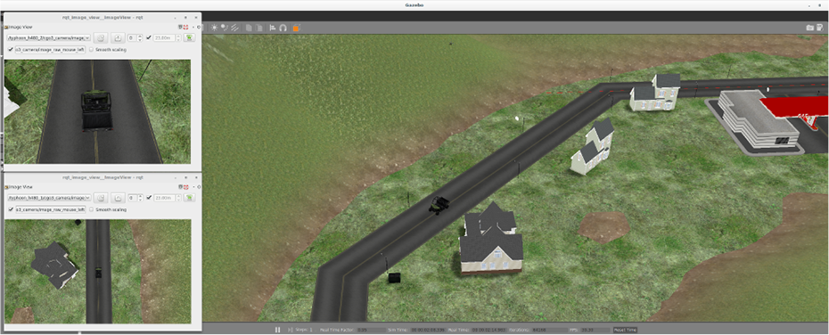
Simulated mockup scenario for MULTIDRONE where two UAVs follow a car taking different types of shots. Views from the two onboard cameras can be seen. UAV: unmanned aerial vehicle.
In this project, UAL is used in its server interface. In the proposed architecture, there is a module in charge of the control of the drone, gimbal, and camera that communicates with UAL server to get the current pose and velocity and to send velocity control commands to it. Moreover, field tests have been performed using this architecture with UAL integrated. In the study by Sabetghadam et al., 22 for instance, some results for autonomous aerial cinematography through UAL are demonstrated.
Autonomous inspection
UAL has been adopted for autonomous inspection with UAVs in different projects and with autopilots. In the AEROBI project, we used it with a PX4 autopilot, whereas in the INSPECTOR project, the DJI A3 autopilot is used.
The European project AEROBI (http://www.aerobi.eu) aims to automate the inspection of bridges’ concrete beams and piers by the use of flying unmanned robots equipped with manipulators driven by an intelligent control and a computer vision and sensing system.
For instance, measuring the deflection of bridges is a tedious operation in which an operator places a tool on the beam with a pole or aided with a crane. The tool is a prism which is used by a Total Station (https://leica-geosystems.com/products/total-stations) to accurately measure positions.
One of the objectives in the project is to use a UAV equipped with such a prism. As described by Sánchez-Cuevas et al., 23 the UAV can use the drag forces generated by the propellers in the proximity to the ceiling to remain stuck to the beam. Therefore, the total station can measure any deformation of any beam at any bridge without putting into risk neither any human operator nor machine.
In that context, the UAL framework has been used to automate the control and movement of the aerial platform during the experimental missions. Figure 12 shows an experiment where the UAV follows a trajectory with three contact points chosen to measure the deflection of a bridge beam. In this particular example, the process of measuring the deflection uses the class interface to make a collection of

UAV measuring beam deflection in a bridge. Left: UAV trajectory during the mission with a point cloud captured by the total station. Right: snapshot of the UAV stuck to the beam. UAV: unmanned aerial vehicle.
The national Spanish project INSPECTOR is another project to use UAVs for inspection and maintenance of unattended facilities. In one of the particular use cases, we developed an outdoor platform to inspect large areas of gas pipelines searching for leaks. We based our system on commercial platforms by DJI and integrated our DJI back end with an A3 autopilot. UAL was used in outdoor field experiments to command high-level exploration missions through the
Aerial manipulation
UAL has also been used for applications in aerial manipulation. First, it was used in the European project AEROARMS (https://aeroarms-project.eu/), where a UAV equipped with a dual robotic arm operates in complex industrial environments for inspection and maintenance. Within the framework of the project, UAL has been extended with similar abstract interfaces to operate the robotic arms. In Figure 13, some experiments in a mockup scenario are shown. In the experiments, a reactive navigation algorithm 14 is used to avoid collisions while operating.

Experiments for aerial manipulation in a mockup scenario emulating pipes in a plant. Real and simulated environments are depicted.
The algorithm uses UAL for state estimation and velocity control, both in simulation and real experiments. In this particular case, the process in charge of the reactive navigation makes use of the class interface, calls the
The UAL UE back end has also been used to test algorithms before deploying then in real platforms. As an example, center image of Figure 8 shows a UAV equipped with a manipulator to grasp objects.
UAL has also been tested in another European project that involves aerial manipulation, the project HYFLIERS (https://www.oulu.fi/hyfliers/). This project aims to develop teams of UAVs to perform the autonomous inspection of industrial environments. Particularly, UAL has been used to control a UAV to autonomously perch on pipes using a zenithal camera. The final objective is to be able to inspect these pipes using contact sensors and even to interact with them. Figure 14 shows the aerial platform used for that purpose.

An experiment for UAV autonomous perching on a mockup pipe for inspection. UAV: unmanned aerial vehicle.
Fast development on robot competitions
The last use case concerns the MBZIRC (http://www.mbzirc.com/), which takes place in Abu Dhabi.
We participated as the Al-robotics team in this challenge in 2017 (see Figure 15), where a team of three UAVs had to perform a mission that combined exploration and picking and placing objects into a box. The participation in this competition and the need for a common framework for both the actual UAVs and the simulation motivated the development of a layer for the PX4 flight stack.

Left: competition arena for the MBZIRC 2017. A multi-UAV team must find, pick, and place a set of objects. Right: the Al-robotics team during the competition. UAV: unmanned aerial vehicle.
Preliminary versions of the current UAL were designed during our participation in the MBZIRC 2017. Later, these first approaches converged and generalized as a framework for interfacing UAVs in a standard fashion. In the competition, the UAVs performed a cooperative mission where they executed an area coverage algorithm (see Figure 16) to search for the objects, and then a task allocation algorithm to get objects assigned for collection. UAL was used by these high-level algorithms to operate the UAVs, for instance, by sending waypoints or controlling them in velocity while collecting the objects. Given the multi-robot character of the application, the server interface was mostly used in this case.

Map of the MBZIRC 2017 arena. The scenario is split into three areas where the UAVs search for objects at the beginning of the mission. The routes assigned to the UAVs are depicted in different colors. The landing zone of the UAVs (LZ) and the dropping zone (DZ) to place the objects are also shown. UAV: unmanned aerial vehicle.
Our lab is also participating in the next edition of the competition, MBZIRC 2020. In the next edition, the challenges have a strong focus on heterogeneous robot cooperation. For instance, UAVs and a ground robot must work together to assemble a wall of bricks or to detect and extinguish a set of fires. The other challenge is about searching, tracking, and catching a ball that hangs from another moving UAV. UAL is being used as the underlying layer of our software architecture to command UAVs and to communicate with the ground robot. For the tasks that require high precision in velocity control, such as picking up and dropping bricks with the UAVs, or reacting fast to track another moving UAV, we use the UAL class interface and its
To face the new competition, we first implemented simulations of all the challenges based on the MAVROS UAL back end, using the PX4 SITL functionality. Then, we ran preliminary tests with our customized platforms based on the new hardware Pixhawk 2. For that, we were using the MAVROS back end too. As we detected some issues with the sensor reading of the Pixhawk that made our controllers unstable, we are now testing in parallel the whole system mounting DJI A3 autopilots on our UAVs. Thanks to UAL, switching between autopilots is straightforward and does not affect the overall project architecture.
Conclusions
This article has presented UAL, a framework to abstract high-level software development in UAVs, allowing users to work with different autopilots and platforms by means of common interfaces. After using UAL within the context of several R&D projects, we can conclude that it eases the development of high-level algorithms. It allowed us to operate a wide variety of aerial platforms with autopilots from the major manufacturers in a transparent manner. Researchers from different organizations have provided positive feedback and found useful UAL as an enhanced middleware. Moreover, the functionality to interface simulated or real UAVs, in the same way, has proved to be quite helpful.
We presented a stable version that is publicly available in Github. 16 However, UAL is in continuous development, adding new features and fixing issues as they are detected. This development is profiting from the use of UAL by the robotics community. In fact, UAL was conceived as a modular and adaptable framework so that users from the community can extend it easily with their own back ends.
As future work, we are constantly working on adapting UAL to newer versions of the platforms already supported. For instance, MAVROS updates are very frequent and we maintain backward compatibility with several previous versions. Besides, we think of migrating UAL to ROS 2 version. Last, we would also like to explore possibilities to enhance the functionalities of UAL to simulate DJI platforms, mainly for multi-UAV environments.
Footnotes
Acknowledgements
The authors would like to thank all the GRVC Robotics Lab members for their valuable feedback and contribution to UAL. Special thanks to Alejandro Castillejo, Héctor Pérez, Manuel Fernández, José Andrés Millán, Ángel Montes, Ricardo López, Pedro Sánchez, Rafael Salmoral, and Víctor Vega.
Declaration of conflicting interests
The author(s) declared no potential conflicts of interest with respect to the research, authorship, and/or publication of this article.
Funding
The author(s) disclosed receipt of the following financial support for the research, authorship, and/or publication of this article: This work was partially funded by the European Union’s Horizon 2020 research and innovation program under grant agreements no. 731667 (MULTIDRONE) and by the MULTICOP project (Junta de Andalucia, FEDER Program, US-1265072).