
Abstract
As the development of multidisciplinary techniques and ever-growing demands, autonomous system has been widely investigated in a variety of fields. In recent two decades, autonomous surface vessels have gained increasing attention from both industry and research communities, previous related work mainly focuses on the design of maneuver controllers, most algorithms are under some specific assumptions and always involve too many parameters that need to be tuned, leading to the lack of practical application or validation in real autonomous surface vessel platform. To tackle the issues, an integrated autonomous surface vessel prototype is designed and implemented, both navigation and maneuver control subsystems are improved, especially in terms of autonomous control, a simple geometrical model and constrained pure pursuit algorithm is firstly tried in autonomous surface vessel, the results show that the proposed system can achieve the path tracking with the error smaller than 40 cm, and even given a complicated waypoint mission, it can still maintain the accuracy of path tracking, demonstrating the stability and validity of the autonomous surface vessel prototype.
Keywords
Introduction
As the development of multidisciplinary techniques, including satellites-based and inertial navigation system, radar, light detection and ranging (LiDAR), vision-based sensors, and other related newly rising advanced technologies, the unmanned and autonomous systems are increasingly coming up to serve our daily life, eventually they have become part of our life. The autonomous technologies have penetrated into a variety of applications, such as the application of autonomous combine harvester in agriculture industry, 1 –3 the employment of intelligent unmanned system in transportation field, 4 and specialized autonomous robots in industrial production lines. In this trend, the reliability and robustness in different working environments must be taken into consideration as the main concerns for the future development.
In recent 20 years, the study in autonomous surface vessel (ASV), sometimes also termed as unmanned surface vessel (USV), has gained incremental attention both in research and industry communities. 5 –7 Theoretically, there are three main subsystems in an ASV, typically termed as navigation, guidance, and control parts. As shown in Figure 1, the navigation component is in charge of the estimates of positioning, attitude, and some other environmental awareness-related properties, in the field of ASV, global position system receiver, compass, and inertial measurement unit (IMU) are traditionally employed to provide the positioning and orientation information, 8 in some experimental ASV prototypes, only stereo cameras are used to sense the positioning and attitude information. 5 In recent years, as the rising of other multiple types of exteroceptive sensors, such as radar and LiDAR are eventually mounted to help sense the complicated environment and in-depth information, 9 acting as artificial intelligence.

Subsystems in an ASV. ASV: autonomous surface vessel.
A robust navigation system is a key component in a variety of autonomous applications, including aerospace, surface, and underwater vehicles, a global navigation satellite system (GNSS)/inertial navigation system (INS) integration system 10 is normally a solution for aforementioned autonomous systems, considering the low-cost mass-market products, there are mainly two issues in GNSS/INS integration system, one is the initialization problem, that the initial attitude needs to be set within an acceptable range of error, otherwise the system will probably diverge or hold huge estimate errors. Even with the correct initial attitude information, due to the low observability of orientation parameter, 11 the estimates of orientation will drift as time is going on. In this sense, additional enhancement sensors like compass, and so on are often deployed to make orientation estimate stable and reliable consistently in long-term operations. 8 On the other hand, as the development of real-time kinematic (RTK) techniques, a multi-antenna attitude determination system using GNSS is proposed in huge cargo ships, 12 RTK-based attitude determination system is totally dependent on the processing of GNSS signal and can avoid the problem of error accumulation as in case of INS, but it relies on the quality of visible GNSS signals, once the inconsistency happens between two adjacent epochs due to unpredicted nuisances including the blockage of some satellites, the interference, and so on. RTK may fail due to the unsolved phase ambiguity.
Compared with navigation part, more scholars in ASV community are focusing on the control part, endeavoring to develop a robust control algorithm dedicated to ASV. Firstly, it is interesting to note that due to the different physical properties, various control models are preferred in the field of ASV and autonomous ground vehicle (AGV), with respect to AGV, geometric vehicle models, kinematic bicycle models, and dynamic vehicle models are often exploited for further controller design, 13 while in case of ASV, kinematic models are widely considered to develop the control algorithm, 14 with the system models ready, point-to-point, trajectory tracking, and path following control approaches for ASV have received increased attention during the last two decades especially in control community. 15 Generally, there are two main challenges for control design, one is the fact that an ASV system is often underactuated, conventional ships are equipped with propellers for driving speed and rudders for orientation steering, but there are normally three degrees of freedom (surge, sway, and yaw) need to be controlled, in this circumstance, the two controls cannot influence all three variables independently, thereby leading to underactuated control, and the other challenge is the inherent nonlinearity of the kinematic models, 16 necessitating the employment of nonlinear control algorithms. Even though there are a variety of available controllers in the literature that can be categorized into feedback linearization and backstepping methods, 14 there are still complexity in the parameter tuning and a lack of the experimental implementation and validation in real scenarios.
In summary, as aforementioned in the concise background, in the field of ASV community, much previous work is dedicated to the theory investigation especially in the design of advanced controllers, but there is still work left to do to improve the ASV hardware design and investigate simple but practically useful control algorithms, to enhance the navigation and control subsystems in an ASV. Firstly, in the second section, the system description is presented including the details of hardware and software in the ASV prototype. Furthermore, a robust navigation system is designed and tested for ASV application in the third section. With the inspiration of AGV controller design, an approximate geometric vehicle model is proposed, and a corresponding pure tracking algorithm is derived and validated in the fourth section. Additionally, dedicated experiments are carried out to verify the system design and future work related to ASV of next generation is proposed in the fifth section.
System description
The ultimate goal in future is to develop coordinated ASV swarms, so the cost of each single ASV is a critical factor needs to be considered in the practical design; in the initial stage, all possible sensors with complicated fusion algorithms can be mounted to evaluate the performance of an ASV, eventually, the equipment will be simplified or to decrease the cost without loss of necessary functions.
To build an ASV platform for a different algorithm validation and an initial general performance evaluation, one vessel prototype with the approximate size of 2 × 0.9 m2 is designed and produced as shown in Figure 2.

The blueprint and real product of the ASV (second generation). ASV: autonomous surface vessel.
In detail, the ASV system mainly consists of five subsystems, separately termed as ground devices, telecommunication, environmental perception, control computer, and actuator part. As shown in Figure 3, the ground devices mainly include a GNSS base station, providing the base measurements to the GNSS receiver in the rover, and a ground monitor used to display the status of the ASV. In telecommunication part, 4G module and other wireless radios using different frequencies are employed to transmit the data, bridging the gap between station and rover.

The hardware architecture.
For the other three onboard subsystems, they may decide the autonomous level 6 and main performance of the system. In the environmental perception part, a navigation system provides positioning and attitude estimates, while LiDAR and camera are used to sense the obstacles or possible collision within a certain range. The perceived information is the basis for the path planning, once the environmental information and the path decision are sent to CPU in control computer part, the command will be generated following the embedded algorithm to control the actuators. Note that generally in case of underactuated ASV, velocity and orientation are commonly the only two available control inputs adjusted separately by propeller and rubber.
Correspondingly in the software part as shown in Figure 4, there are mainly three components including navigation, path planning, and maneuver control. In this article, navigation and maneuver control will be concerned. In the navigation part, RTK is firstly considered since it can provide the positioning service with the accuracy up to centimeters, which also guarantees the reference for the performance evaluation of control algorithms. Even practically due to the harsh environment, RTK may fail in some cases, the GNSS/INS integration system will take it over to keep the accuracy to the maximum extent. In the orientation estimation, two options are employed, one is the orientation estimates from GNSS/INS integration system, and the other is directly computed from multi-antenna GNSS signal processing. Considering the drift of orientation estimates in GNSS/INS and occasional unavailability of orientation estimates in multi-antenna GNSS processing system, a simple combination of these two aforementioned options is adopted in the ASV to provide a robust navigation system. Additionally, a camera and LiDAR are integrated to sense the abrupt conditions or obstacles by point clouds processing, so as to plan the real-time path in an autonomous and flexible manner. Once the path mission and current environment information are obtained, the core computer will compute the commands following the predefined controller to do the maneuver control. Particularly, in the carryout of orientation control, a second-order phase lock loop (PLL) is exploited to smooth the control promptly.

The key software architecture.
In summary, the navigation subsystem and maneuver control are basic and important in our vessel design and practical implementation, more details can be referred to in the following sections.
Navigation system
In terms of environment perception, position, velocity, timing, and attitude (PVTA) is fundamental information for an autonomous system, which can affect the related actions including path planning and vessel maneuver control. In this sense, a robust navigation is a primary subsystem with the property of robustness and reliability. In this article, a navigation subsystem as shown in Figure 5 is developed and tested in real scenario through car experiments.

The structure of navigation subsystem.
General description of the navigation system
In this project, a GNSS/INS integration system is firstly employed, then to solve the orientation drift and initialization problems, a self-developed multi-antenna GNSS-based orientation determination system is added as an auxiliary component to make up for the shortcomings of both separate systems.
As shown in Figure 6, the loose GNSS/INS integration system mainly fuses the position/velocity results from GNSS receiver and IMU system using integration filter (normally a Kalman filter); meanwhile, the IMU errors can be estimated and fed back to the mechanism part to do the correction, suppressing the observable drift error. More details are expanded as follows, in the INS mechanism part, the estimates of position/velocity in INS are updated through dead reckoning. It mainly involves velocity update, position update, and attitude update as shown in equation (1)
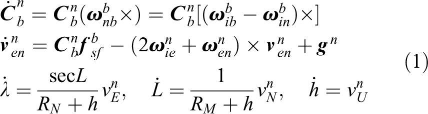
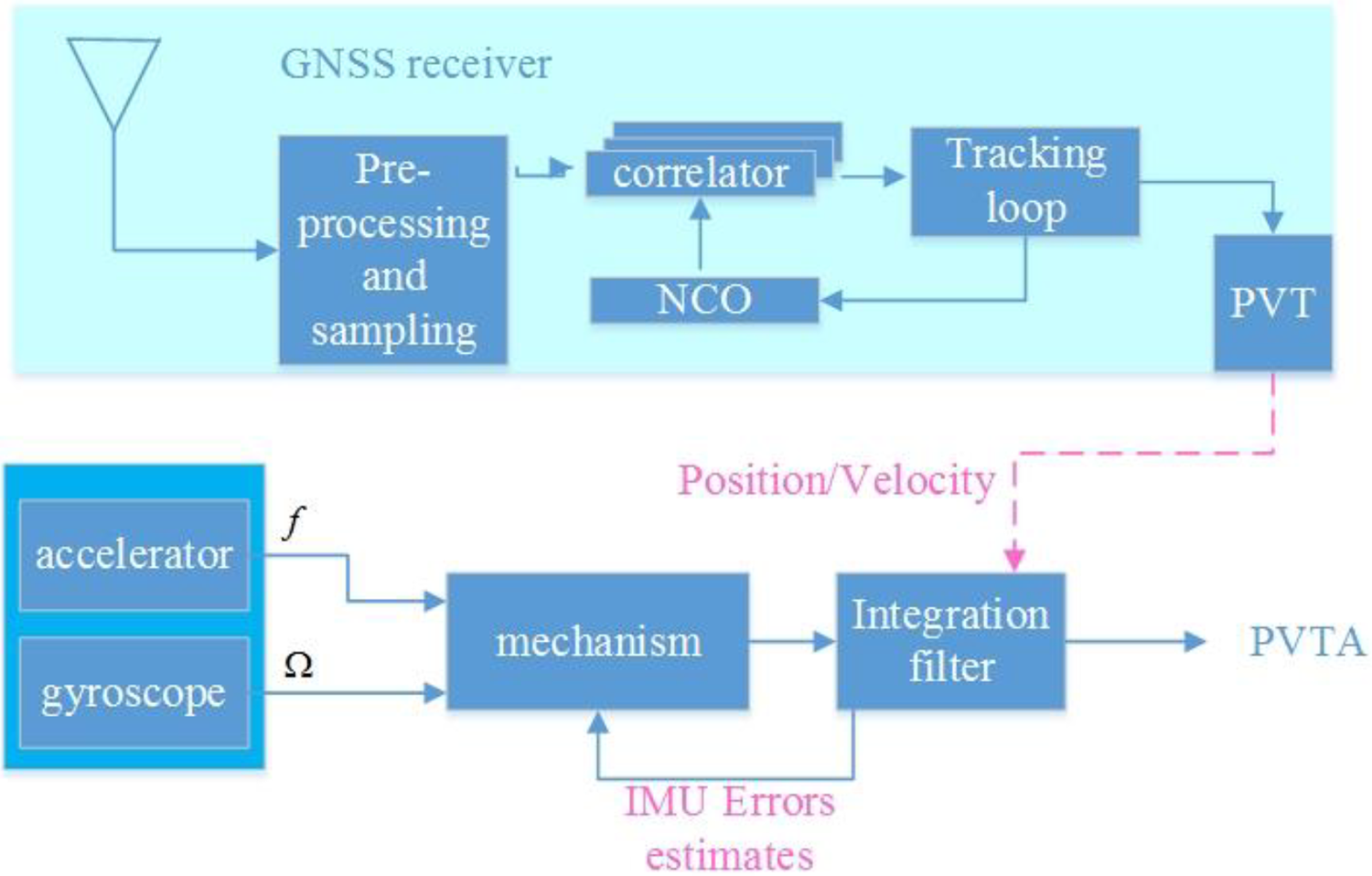
The diagram of a loose GNSS/INS integration system. GNSS: global navigation satellite system; INS: inertial navigation system.
where
Considering the low-end IMU (MPU 9250) used in the project, in the computation of rotation vector during process of equation (1), a simple noncommutativity error compensation algorithm as written in equation (1) is exploited as

where
Furthermore, with the system of attitude error, velocity error, and position error described in equation (1)

where operator δ means the error of something, φ represents the attitude error,

where state vector
Due to the poor observability of orientation parameter in system (4), 11 the estimates of orientation will drift eventually especially when there is no large maneuver. In this sense, the orientation evaluation should be enhanced by additional related measurements. In this project, a dual-antenna GNSS-based orientation determination system is deployed as additional augmentation.
With respect to the multi-antenna orientation determination system, in this project, only two antennas are employed to compute the orientation information by RTK technique. The detailed diagram of the data processing is shown in Figure 7.

The process of orientation computation.
Suppose two antennas marked as base and rover in Figure 8 are available, the pseudorange and phase-range measurements can be described in equation (1)

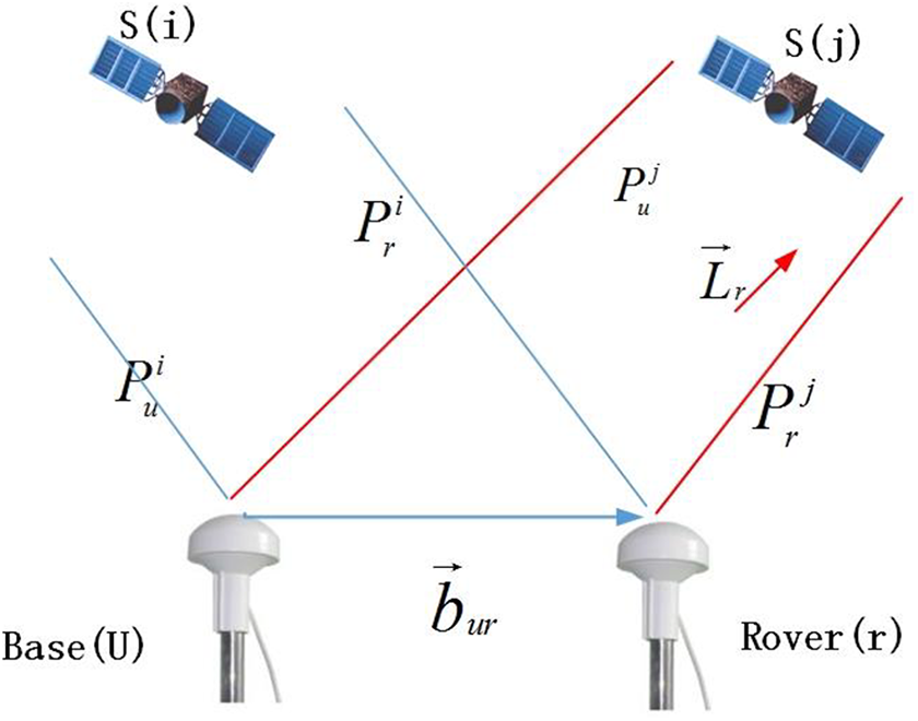
The demonstration of RTK. RTK: real-time kinematic.
where P represents the pseudorange measurements, φ represents the phase measurement, N is the unknown phase ambiguity, R is the true distance between receiver and satellite,

where Δ∇ represents the DD operator,

where
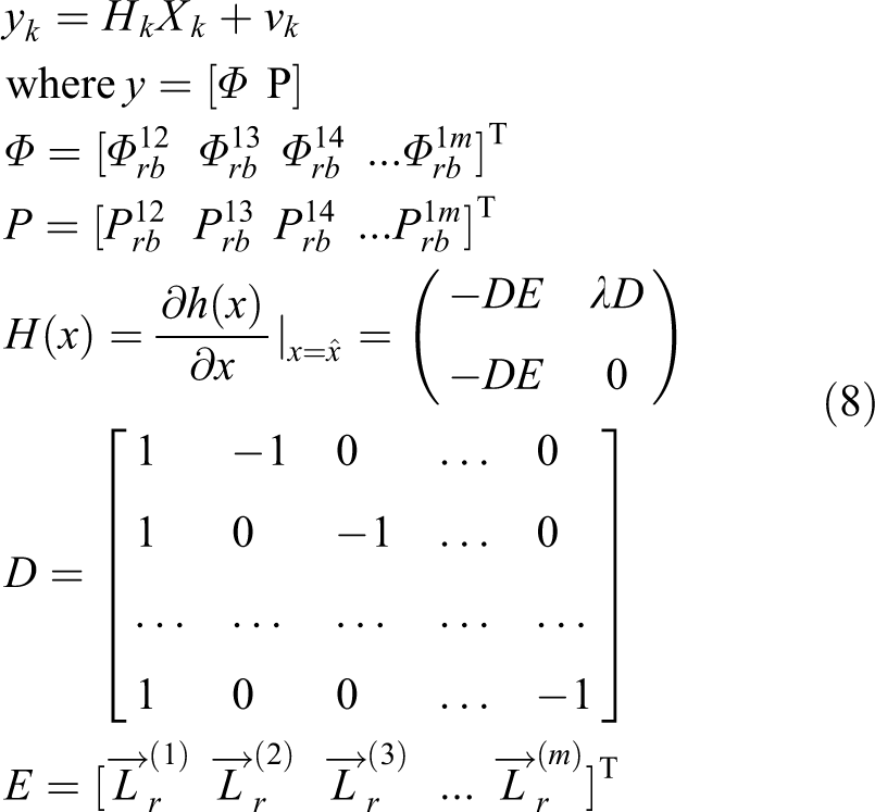
where Φ and P are the DD measurements computed in equation (1). Through the EKF system described in equations (7) and (1), in every iteration, a vector of float solution can be obtained, then it will be fed into the Least-squares AMBiguity Decorrelation Adjustment (LAMBDA) module for the resolution of DD phase ambiguities, once it succeeds in LAMBDA process, a baseline vector
Experimental validation of the navigation system
To evaluate the performance of the proposed navigation system as shown in the first picture in Figure 9, for convenience, a small-scaled car experiment is carried out in the suburb of the city. An RTK base station is employed to supply the measurements to the rover to get high-precision positioning results. Meanwhile, an inner RTK between two antennas is also executed to do the orientation estimation. Note that even there are four antennas mounted on the top of the car, but only three of them are used, in future work, the rest one will be used as a backup.

The self-developed multi-antenna GNSS-based orientation determination product (using NV08C-CSM and MPU-9250) and the setup of experiments. GNSS: global navigation satellite system.
The experiment results are illustrated in Figures 10 and 11, both the trajectory and attitude results are shown, indicating the expected function of the navigation system. It should be noted that there is no perfect reference during the experiment, since for the maneuver control of the ASV in this article, an orientation estimate with accuracy within 1° is acceptable, so no further evaluation is done at the moment, but in future, more in-depth work will be continued and more rigid evaluation will also be presented.

The position results.

The attitude estimates (yaw is computed using dual-antenna GNSS-based orientation determination system). GNSS: global navigation satellite system.
ASV maneuver control
With the navigation system ready, which can supply the critical information including PVTA. In the following stage, an autonomous strategy needs to be determined for a different requirement of autonomous level. 6 As mentioned in the “Introduction” section, actually a lot of literature works are available regarding the control algorithms in the field of ASV, but there is normally hardness in parameter tuning and a lack of experimental implementation. In the remainder of this section, a simplified model and path tracking algorithm will be proposed according to the property of the ASV prototype.
A simplified geometric model of the ASV prototype
Conventionally, the most widely used control-oriented planar surface vessel models have the following general form written in equation (1) in the body frame 5

where
As shown in Figures 2 and 12, the first generation and second generation of our ASV prototypes are both equipped with rudders and propellers mounted at the middle of the rear brink in the hull, and this is the only power supply. Inspired by the bicycle model in the field of AGV, 13 the first experiment where the angle of the rudder is set to a constant is attempted.

The first generation of the ASV. ASV: autonomous surface vessel.
From the results in Figure 13, it can be concluded that once the rudder is hold, the trajectory of the ASV can be approximately as a circle with a certain radius, and apparently the size of radii depends on the value of rudder’s angle. In this sense, a dedicated bicycle model can be derived as shown in Figure 14.

The trajectory of the ASV with the rudder hold to a constant angle. ASV: autonomous surface vessel.

The simplified geometric model of the ASV. ASV: autonomous surface vessel.
From the result in Figure 13, a simplified geometric model resembling Ackerman steered vehicle model as shown in Figure 14 is proposed, suppose the angle of the rudder is δ and the trust force is f, then the front edge of the vessel will move along the circular arc with a radii equal to R. Then a simple geometric relationship can be written as

where L is the distance between the front axle and the rear axle in the simplified model and R is the radius of the circular arc.
Maneuver control strategy
With the simplified geometric model, similarly an angle-constrained pure pursuit strategy is employed as the control strategy, dramatically simplifying the maneuver control algorithm especially in the practical implementation of an ASV prototype. Generally in this article, the maneuver control mainly consists of two parts, one is the control of trajectory and the other is the control of rudder angle.
As shown in Figure 15, the following equation can be derived as


Pure pursuit algorithm.
Recalling equation (1), it can be obtained that

where
Practically, the planned path is normally linear or a circular arc, once the target path is linear as in our project, the computation of
As shown in Figure 16, the computation of


Linear planned path.
where Pe
is the lateral distance from hull to the objective path as marked in Figure 16,

According to equation (1), in every epoch, Pe
and
Once the target angle δ is computed, then to manipulate the rudder to achieve the goal angle, an angle lock loop (ALL) is proposed as shown in Figure 17 to help the adjustment of the rudder angle in a swift and smooth manner.

Angle control loop.
The proposed ALL actually resembles the traditional PLL 20 in GNSS tracking part, in this project, a second-order lock loop is employed

To set a and b appropriately in equation (1), the transfer function of the system is firstly derived as in equation (1)
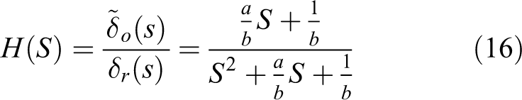
Apparently, the transfer function in equation (1) conforms with the following transfer function

where ζ is the damp ratio, wn is the natural frequency of the system. With the comparison between equations (16) and (1), the following relationship can be obtained as
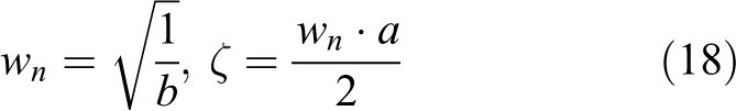
Normally, the damp ratio ζ is set to 0.707, the computation of wn can be achieved from the perspective of the equivalent noise bandwidth of the system 21 in equation (1)

The setting of BL is the balance between dynamic performance and accuracy, in this article, BL is set to 2 Hz considering the condition of ASV.
Experiment and conclusion
With the system ready, a small-scaled experiment is done in a peaceful lake. Note that only navigation and maneuver control subsystems are initially validated, with respect to the obstacle avoidance function, here in this article, it will not be involved. Different typical missions are planned, including the linear path and waypoint assignments.
As shown in Figure 18, the size of lake is nearly 90 × 60 m2, which is sufficient for basic experiments of the ASV. Firstly, a simple point-to-point mission is assigned to test the performance of linear path tracking. The result is shown in the left picture of Figure 19, the length of AB line is nearly 54 m, and the maximum path tracking error is close to 40 cm. Considering the environmental interference, such as the current, wind, and other nuisance, the accuracy conforms with the expectation. When a round trip from A to B assignment is sent as shown in the right picture of Figure 19, it can be seen that there is a big turning at point B due to the huge difference between the target orientation and current orientation, as depicted in the right part of Figure 19, when the vessel arrives at B, then it has to turn to the opposite direction to move back to the starting point A following the task, because of the existed velocity and angle limit of the rubber, the maximum path tracking error can be up to 7.7 m. To decrease the error in this extreme case, a simple strategy is proposed, that is, once the target angle changes abruptly with big amplitude (such as more than 30°), the velocity of the vessel is controlled to be close to zero swiftly, subsequently the orientation of the vessel is controlled so as to be closed to the target orientation, and finally the full control strategy resumes. The validation is shown in the next experiment as shown in Figure 20.

Lake environment.

AB linear course test.
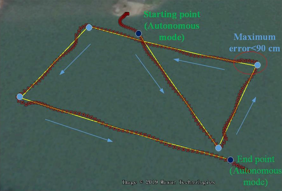
The waypoint experiments.
And in the second assignment, six mission points are defined in advance, when the vessel comes close to the first point, the working mode changes to autonomous mode, and in the following move, the vessel tracks the path automatically, inside the point-to-point linear path, the accuracy still remains within 40 cm, every time when the vessel come close to the mission point, the velocity is decreased (if the difference between current orientation and the next target orientation is exceed the threshold such as 30°), preparing for the turning. As shown in Figure 20, apparent errors that sometimes reach up to 90 cm happen in the corners, but it is still definitely an improvement compared with the result in the right part of Figure 19, and the main reason for the error is due to the big turning and the inertia of the vessel.
In summary, the experiment results validate the effectiveness of the navigation system and control strategy, especially in the latter component, a simple geometric model is proposed and a pure pursuit algorithm that has never been applied in the field of ASV is employed, with some specific constrains, the performance conforms with the expectation.
For the future work, in the navigation part, an INS-aided RTK will be investigated and studied, while in future controller design, a more accurate kinematic model of the vessel will be investigated and studied to improve the path tracking performance especially with the existence of common interferences, and the fusion of all other sensors including LiDAR and camera will also be integrated in one single engine to achieve all-source navigation system.
Footnotes
Declaration of conflicting interests
The author(s) declared no potential conflicts of interest with respect to the research, authorship, and/or publication of this article.
Funding
The author(s) disclosed receipt of the following financial support for the research, authorship, and/or publication of this article: This work was supported by the National Natural Science Foundation of China (41704025), the Aeronautical Science Foundation of China (20170869005), Zhishan Youth Scholar Program of Southeast University, Primary Research & Development Plan of Jiangsu Province (BE2018384), Natural Science Foundation of Jiangsu Province (BK20160668), and Foundation of Shanghai Key Laboratory of Navigation and Location Based Services.