
Abstract
Coverage path planning technique is an essential ingredient in every floor cleaning robotic systems. Even though numerous approaches demonstrate the benefits of conventional coverage motion planning techniques, they are mostly limited to fixed morphological platforms. In this article, we put forward a novel motion planning technique for a Tetris-inspired reconfigurable floor cleaning robot named “hTetro” that can reconfigure its morphology to any of the seven one-sided Tetris pieces. The proposed motion planning technique adapts polyomino tiling theory to tile a defined space, generates reference coordinates, and produces a navigation path to traverse on the generated tile-set with an objective of maximizing the area coverage. We have summarized all these aspects and concluded with experiments in a simulated environment that benchmarks the proposed technique with conventional approaches. The results show that the proposed motion planning technique achieves significantly higher performance in terms of area recovered than the traditional methods.
Introduction
Floor cleaning robots are becoming an integral part of every household that could improvise the productivity and quality of life through performing repetitive and time-consuming task. It is estimated that cleaning robots could reach a market value of USD 4.34 Billion in 2023, wherein the floor cleaning robots will hold a more significant share. 1 Even though the dominant market player iRobot, Neato, Samsung, and Xiaomi claims that they have sold millions of units, there exists numerous research challenges and open questions to be addressed. Such research initiatives have continually pushed the performance limits of floor cleaning robots in the areas of mechanical design, 2 autonomy, 3 human–robot interaction, 4 and performance benchmarking. 5 Even though the diverse literature on floor cleaning robot demonstrates its benefits and the translation from abstract design to commercial technology, the conventional robots endure from a series of performance degradation. One primary attributes that curtail the efficacy of the floor cleaning robots is their fixed morphology design, which restrains their accessibility in constrained spaces and weakening area coverage. We proposed an alternative design in the works of Prabakaran et al. 6 and Le et al. 7 to overcome these bottlenecks in the traditional cleaning platforms where we introduced a next-generation of reconfigurable floor cleaning robot named “hTetro” inspired from the game called Tetris. The developed robot is capable of reconfiguring its morphology to any of the seven one-sided Tetris pieces which aid the robot to achieve superior area coverage performance than a traditional fixed morphology cleaning platforms.
In the process of developing a floor cleaning robot, it is critical to address its capacity to demonstrate autonomous and efficient coverage path planning (CPP). Similarly, in the case of hTetro, it is crucial to establish its CPP intelligence. CPP is an exciting field of study for robotic scientists with numerous research literature. One common technique that has been extensively utilized for CPP task is cellular decomposition. This method breaks down the workspace into small cells and applies motion planning to each cell to cover the entire region. Numerous other methods have been proposed to decompose the given space that includes trapezoidal decomposition, 8 boustrophedon decomposition, 9 Morse-based cellular decomposition, 10 among others. Wong and MacDonald proposed a topological area coverage technique that could point landmarks as nodes to cover the area. 11 In another work, a sensor-based coverage technique was proposed by Butler et al. 12 The proposed method uses sensed robot data to generate paths that could reach a possible point to achieve maximum area.
Grid-based area coverage methods are in use over the last three decades, wherein the workspace is treated as uniform grid cells, and each cell contains a value which replicates the presence of an obstacle. There are numerous algorithms proposed towards realizing grid-based coverage such as wavefront algorithm, 13 spanning tree technique, 14 hexagonal grid decomposition, 15 and graph theory-based coverage. 16 Xu 17 presented a graph-based CPP technique, in which he considers the mapped area as a graph and applies robot motion planning to reach every coordinate point in the graph. In recent years, several 3-D area coverage techniques have been proposed and validated in the context of service robots. For instance, Cheng et al. applied 3-D coverage to inspect urban structure. 18 Galceran and Carreras proposed a bathymetric 3-D map to inspect ocean floors. 19 Jin and Tang proposed a 3-D coverage algorithm for agriculture purpose. 20 Other CPP techniques like optimized 3-D coverage and multi-robot coverage strategies were discussed in Galceran and Carreras. 21 Even though there is numerous literature that demonstrates the application of CPP techniques in robotic systems, the current approaches are mostly limited to fixed morphological platforms. Also, none of these existing techniques were realized on a reconfigurable robot in the context of a meaningful application.
Reconfigurable robots were introduced in the late 1980s and have been extensively studied since then. Transformable robots are classified into three major categories, namely, intra-reconfigurable, inter-reconfigurable, and nested-reconfigurable robots. Inter-reconfiguration is where an individual robot can change its morphology from one form to another. Some examples to this end include Scorpio, 22 a bio-inspired robot capable of switching between rolling, crawling and wall climbing forms, and Panthera, a reconfigurable, could change the width for pavement cleaning. 23 Inter-reconfiguration is where multiple similar robots come together to form global morphologies by undergoing assembly and disassembly process. Precedents include CEBOT, M-TRAN, ATRON, CKBot, and Molecube. The third category is nested robots, which are capable of performing both inter- and intra-reconfigurations. One such example is Hinged-Tetro, a robot that can change its morphology on its own and can form global morphology by attaching and detaching with a team of other Hinged-Tetro robots. 24 With a wealth of literature covering different aspects of reconfigurable robots, connection to meaningful applications such as floor cleaning has always been weak. Also, there are minimal studies on CPP in the context of reconfigurable floor cleaning robots. To this end, a novel CPP strategy was proposed in one of our previous work 25 for the hTetro robot based on the polyomino tiling theory. In that work, we validated the application of polyomino tiling theory in the context of area coverage. The work analyzes the hTetro’s system architecture, the Tetris theorems that have been validated, and concludes with the experimental results shows superior area coverage. However, the generation of the tile-set and the robot’s coverage process were executed involving manual support without any motion planning strategies. In the current work, we are proposing a motion planner framework, which can autonomously generate the tile-set and its coverage route for the hTetro robot to achieve maximum area coverage.
In most cases with CPP strategies, the commonly used motion planning algorithms are spiral motion, backtracking spiral motion, and boustrophedon (back-and-forth) motion. For instance, Jin and Tang proposed a decomposition method in order to cover the farming field using boustrophedon paths. 20 Similarly, Hameed et al. proposed a genetic algorithm for CPP and used boustrophedon paths for coverage. 26 A time and energy-efficient online CPP technique are proposed in Hsu et al., 27 wherein they adopt a high-resolution grid map representation and utilized spiral path motion to perform adequate coverage. In another work, Gabriely and Rimon applied the spiral motion in a cellular decomposition coverage technique. 14 Gonzalez et al. utilized backtracking spiral motion in an approximate cellular decomposition area coverage method. 28 Also, they proposed an improved spiral algorithm in order to consider the obstacles inside the grid space. 29 Even though there is numerous literature demonstrating the advantages of existing motion techniques in the context of CPP, there is a massive gap in implementing those techniques on robots with the reconfigurable base. In particular, the hTetro robot will assume different heading direction for different morphology so requires a unique motion planning algorithm in order to achieve better performance.
In this article, we are proposing a novel motion planner for the Tetris-mimicked reconfigurable floor cleaning robot that creates waypoints to navigate on the generated tile-set to cover the unified area. The proposed motion planner framework has been divided into three stages. The initial set is for planning, where the high-level global coverage planning will be performed based on the tiling theory. The second set is the generation stage, which produces the path (i.e. motion planning) to cover the area. The last stage set is the execution stage, where the robot performs navigation with appropriate morphology. In this article, we reviewed the fundamental challenges of the proposed scheme such as realizing the generation of the tile-set, motion pattern, reconfigurable ability and translating the theoretical tiling approach through the analytical process into demonstrable systems. This article discusses all these aspects and concludes with experimental to validate the efficiency of the proposed approach. We systematically benchmarked the performance of the proposed approach with few conventional motion planning techniques used in CPP (i.e. spiral, boustrophedon motion, greedy search, and random search) concerning area recovered. The motion planner herein presented is a critical effort towards designing a self-reconfigurable robot that is capable of generating global tile-set, determining correlated global and local trajectories, and generating relevant motor signals based on inverse kinematics and dynamics model.
hTetro: A reconfigurable cleaning robot
hTetro is a Tetris-inspired robotic floor cleaner which can change its morphology to any of the seven one-sided tetromino pieces, as shown in Figure 1. The concerned robot was developed under the principle of hinged dissection of polyominoes. 30,31 The hTetro robot consists of four equivalent square blocks with each block dimension of 25 × 25 cm2. Three hinged points connect the blocks with LLR (Left Left Right) configuration. The platform, as shown in Figure 1, consists of four modules connected by three passive hinges. Each of the modules has a differential-drive locomotion module driven by two 12 V DC motors, as shown in Figure 2. The locomotion modules are connected with the four blocks through the bushing on the central rod. Hence, the angle of each locomotion module is independent of its block. The angles of the locomotion modules are measured using the absolute encoders. These locomotion modules are responsible for both navigation and reconfiguration. At the end of each shape-shifting process, we lock the blocks using an electromagnet to maintain the shape while navigating. Whenever the robot receives a morphology change request, the locomotion modules will perform the shape-changing operation first, before it proceeds with navigation. For every movement, the position of all four locomotion modules is controlled separately through a feedback system. Concerning electronics, we separated it as global and local peripheries. The global components such as LIDAR, IMU, and Intel Compute stick (microprocessor with Ubuntu OS) act as a top layer which helps the robot to perform simultaneous localization and mapping (SLAM) and autonomous navigation. Since block 2 acts as an anchor point for hTetro, we hosed the global peripheries on the second block. The local components such as motor driver (roboclaw), electromagnet (EM), limit switch (LS), absolute encoders (AE), motors (M), and its encoders (En) would execute the reconfiguration and locomotion of hTetro. Electromagnets are used to hold the position of the block that would maintain the morphology during navigation. Limit switches were used to ensure the completion of reconfiguration and to detect the morphology failures. Except in block 2, we housed two sets in block 1, and four and three sets in block 3 of EM and LS components. When it comes to locomotion, we have a set of motor driver, motor, and encoder in each block. We used roboclaw motor driver to control the motors and to collect the encoder signals which will be transferred to the local controller. On top of every locomotion module, we housed an AE that could sense the angular position and send the data back to the controller. Almost every local peripheral’s data acquisition is made by the local controller for which we employed Arduino Mega that is housed in block 2. Arduino Mega (microcontroller) is the only local components that communicate with compute stick and distributes the commands to low-level peripheries to perform tasks effectively. On top of that, we housed four more micro DC motor in every block which actuates the sweepers to pull all the debris into the robot modules during locomotion. In the hTetro system, we used three cleaning modules due to the reason that it may not clean the area entirely in particular shapes. For instance, if we are using cleaning modules only in module 3 and 4, then in “O” shape the areas that segment 1 and 2 covering might not be cleaned. A specific system components of the hTetro robot is shown in Figure 3. The assumptions of modeling are (1) the robot does not perform shape changing during locomotion. In other words, it is treated a rigid platform during the locomotion. (2) The wheels roll with no slipping and no skidding during the locomotion. In this article, the local and global references of the hTetro robot were fixed on block 2. The following section details the hTetro robot’s system model setup on a workspace.

hTetro robot’s seven configurations.

Locomotion module of hTetro.

hTetro robot schematic.
Workspace model
Let us consider the workspace as W wherein the concerned robot A is navigating. The reference frame F for the workspace and the robot is expressed as FW
and FA
. The dimension of the Cartesian workspace is denoted as YW
for Y coordinate and XW
for X coordinate. The defined workspace is then disintegrated into square grids, wherein each grid cell size (denoted as

hTetro robot’s system model on workspace.
hTetro on a workspace
Since the hTetro robot consist of four blocks and each of those occupies a single cell in the grid, we have given a geometric representation for all four blocks as

where


Similarly, it is critical to acquire the robot’s grid position information which provides the ith row and jth column. While considering the hTetro robot, we get four grid positions, which are the crucial block information at any point of operation. Consider G as the entire grid cells generated; each grid information represented as
where
When there is an obstacle O introduced on the workspace, each
hTetro robot navigation on the workspace
The hTetro robot consists of navigational components in most blocks which benefit smooth locomotion. Since the concerned robot’s base is reconfigurable, achieving differential movement is very challenging. Hence, we developed linear locomotive gaits, which cause the robot to traverse forward, backward, leftward, and rightward motions. In order to achieve the mentioned motion capability, we used differential wheels in each block of the hTetro robot. The proposed motion planning strategy produces a series of waypoints

hTetro robot command table.
Motion planner framework for hTetro robot
This article presents a novel motion planner framework (Figure 6) for the hTetro robot over complete coverage tasks where the choice of feasible global, local path, and morphology of the robot is critical for achieving the set performance targets. The proposed framework could be scalable across intra-, inter- and nested reconfigurable systems with minimal modifications according to its application. It allows a concerned robot to evaluate the geometry of the environment, compute desired body morphology, select associated local and global optimal trajectories, and generate appropriate motor primitives. He proposed framework consists of three stages: planning stage, generation stage, execution stage.

The proposed motion planning framework.
Planning stage
Precise sensing of the environment is critical to perform a better area CPP. The process of generating the map of test space is the initial task in our proposed framework. Once the map is generated, it will automatically give out the total number of grid cells it occupies. Each cell (
Generation stage
Next, we use the tile-set matrix to generate the navigation path that achieves maximum coverage. We further divided this stage into subtask that simplifies the process of the area coverage for the concern robot. Since the hTetro robot could cover four grid cells at any point in time, it is critical to find the reference cells, which acts as a waypoint for the system to navigate. The reference generator marks the reference cells, which can be a possible waypoint for the hTetro robot. The motion path generator executes the plan of sequencing the reference cells. The accomplishment of the reference point arrangements produces navigation plan for the hTetro robot. Also, this task produces the waypoints
Execution stage
In the execution stage, the controller receives a series of states from the generation layer. After receiving the state information, the controller executes navigation and morphology shifts. We use a feedback controller which could generate the motor primitives for the current pose of the robot in order to achieve the received state. Similarly, the controller could perform the same set of actions for all provoked states, which ultimately leads the robot to cover the entire area. In this article, we are only discussing the planning and the generation stage.
Strategy for generating tile-set based on tiling theory
Implementing existing area coverage approaches on the reconfigurable platform involves several challenges due to its geometrical changes in every configuration. We adopted the polyomino tiling concept as an area coverage technique in our hTetro robot. A polyomino tiling is a process of placing tiles in a plane using any number of polyominoes pieces which is widely used in gaming
32
and rendering purposes.
33
Since the hTetro robot has seven different shapes, it is inefficient in terms of power and computation, when we use all seven configurations to cover the given area. So, we implemented Tetris tiling theorems to reduce the number of shapes that are used to cover the given area. Tetris tiling theorems is a branch of mathematics which provides a possible tiling set to cover a given
Choosing a theorem
Before going to the tiling process, it is crucial to choose the possible Tetris shapes to fill the given area. In order to achieve that, we have to first choose the best tiling theorem. The best way to choose a tiling theorem is to find the size of the provoked matrix Mt
. Let m and n be the total number of rows and columns of matrix Mt
. Since we are considering Tetris pieces which consist of four equivalent squares, any rectangular grid that is divisible by 4 can be tiled fully with any combination of Tetris pieces. For instance, in the considered matrix, if
Theorem 0.1 (TH1)
An One side is divisible by 4 or
While mapping an unknown environment, it is impractical to expect the total grid occupied could be a factor of 4. In such cases, we must use other relevant theorems to tile the defined space. If the dimensions are not exactly a factor of 4, then we will not obtain a complete tiling. We may have to leave one to two cells untiled in all possible situations. When the theorem is applied to the generated matrix Mt , one to two matrix element’s values are neglected to default. These elements may also consider as an obstacle. Other relevant Tetris tiling theorems that can be chosen in the condition as mentioned earlier are furnished below.
Theorem 0.2 (TH2)
Let a and b be integers that are strictly greater than 1. As such, the “T,” “S,” “Z” tetrominoes can tile a modified rectangle of side a and b if and only if either
Theorem 0.3 (TH3)
The “O,” “L,” “J” tetrominoes can tile a deficient rectangle of side a and b only if
The missing cell has to be on the odd position if the rectangle is (4 m + 1) × (4 m + 1), m ≥ 1 and in an even position if the rectangle is (4 m + 3) × (4 m + 3), m ≥ 1.
35
Placement of tiles
The first step in the process of tiling the matrix Mt
is to find the possible placements of all selected pieces. When the number of selected Tetris shapes (among the available seven one-sided Tetris shapes) is more, then it requires excess time and memory to complete the tiling action. In order to obtain the appropriate tiling set, we utilized bipartite relation
36
between the placement and the matrix elements. For instance, Figure 7 describes the typical association of the placement graph wherein we restricted to Tromino (a type of polyomino that contains three equivalent square blocks) for better understanding. The figure illustrates a

Tile placement map.
The next step is to search the best element to place the tile, which illustrated in Figure 8. We use a backtracking algorithm to search for the best element

Searching the best element in the matrix to place a tile.
Generation of tile on matrix Mt
The matrix Mt
was generated in the planning stage after the stage of occupancy grids. As explained previously, each element of Mt
holds a value
The random tile-set generated.
Placing tile in matrix Mt .


Strategy for motion planning
In most grid-based CPP techniques, each cell represents the full robot (i.e. each cell is robot sized). So the path planning scheme needs to pass the grid coordinates to achieve the full coverage. Since the hTetro platform is unique in its reconfiguration ability and it covers four cells in a grid at any point of time, the path planning technique should generate reference coordinates for every tiled piece in order to accomplish the tiling motion strategy. The generated coordinates will be tagged with block 2 (B
2) for all seven hTetro’s configurations. These coordinates will act as a waypoint WP for the robot that aids to achieve full coverage. On the other hand, the previous coverage motion planning techniques never concern the robot’s orientation because of their fixed morphology. Positioning the heading angle in every coverage platforms is treated as a control problem. Whereas with the hTetro robot, it also requires an orientation reference, due to its directional shift that takes effect after every morphological movement. Acquiring the tiling matrix Mt
and G information as an input for this stage of operation to produce a series of WP, which consist of hTetro robot’s state Q, where
Generation of reference cell
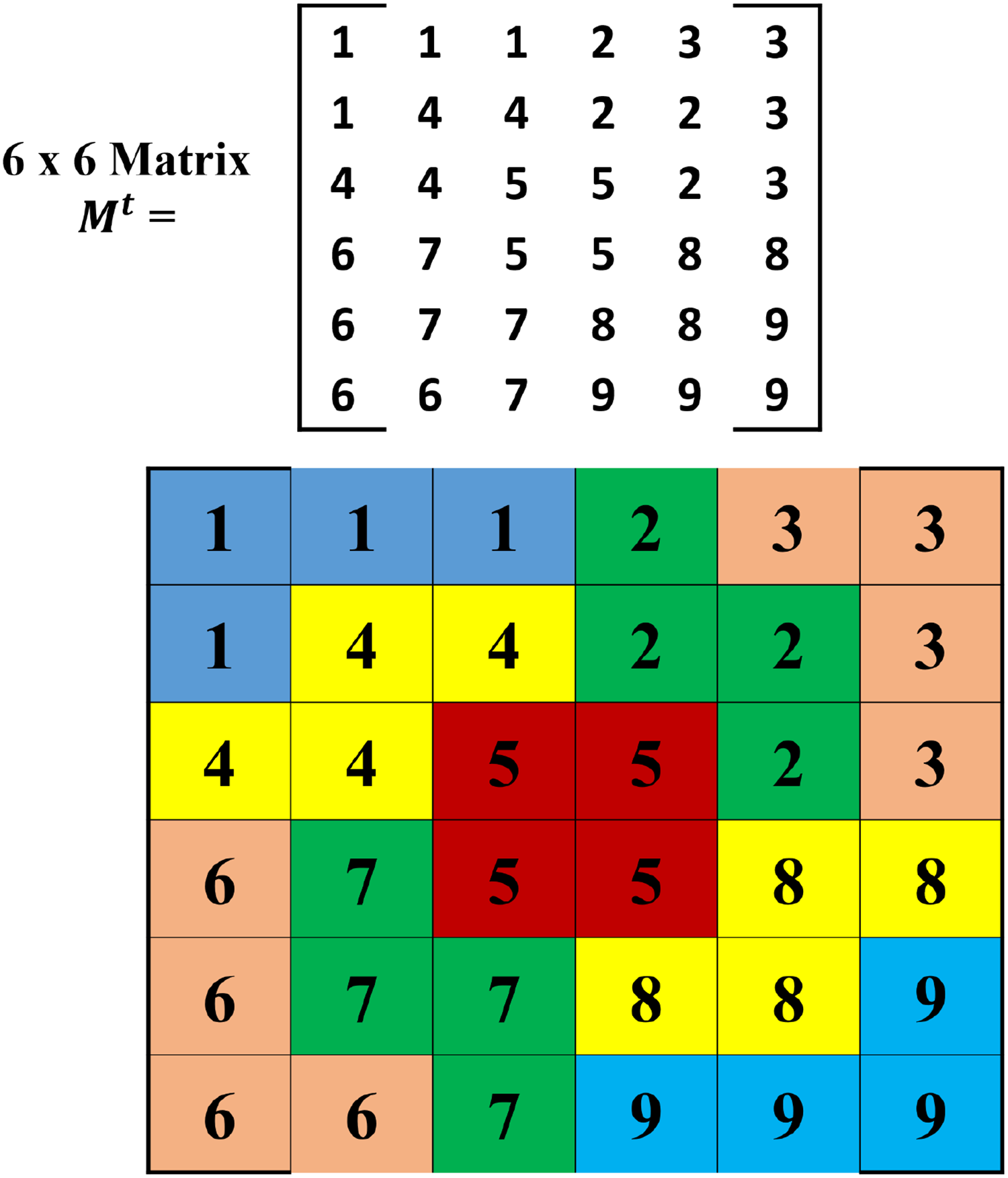
For better reference cell identification, we required two information that includes the tile type and its placement orientation. This two information we can acquire from the produced Mt
matrix. As we know, each tile pieces that were placed in the matrix Mt
holds a unique number Pn
in ascending order, which is also the R value for each element on the particular tile. Every R value should occupy four different elements


The tile value and global orientation for tile “T.”

hTetro robot’s Tv values and corresponding Q values.
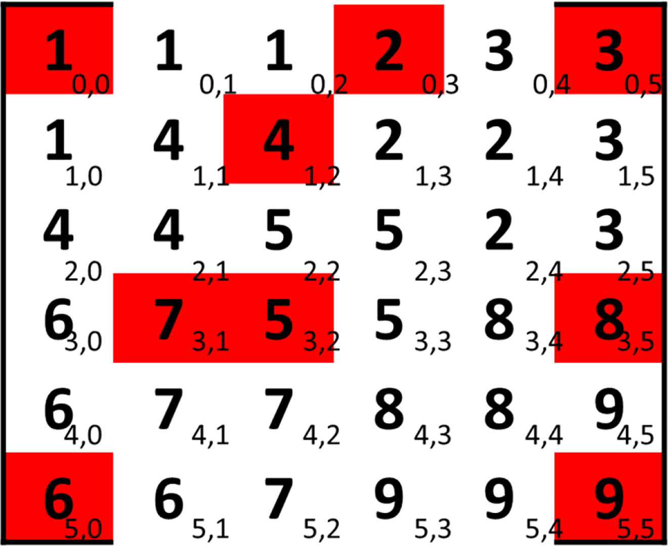
Example reference cell generation in a tiled matrix.
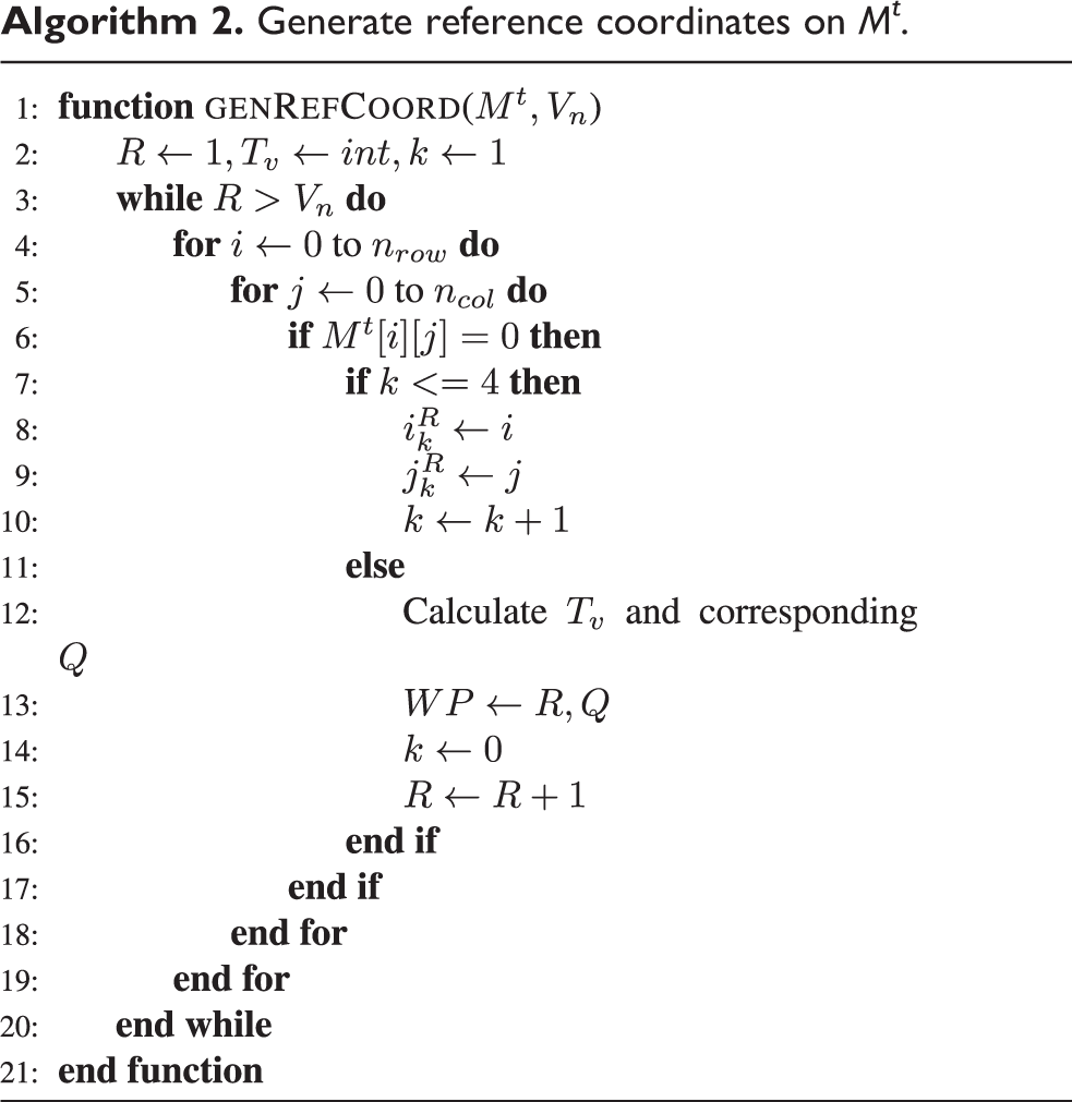
Generate reference coordinates on Mt .

Sequencing of reference cells
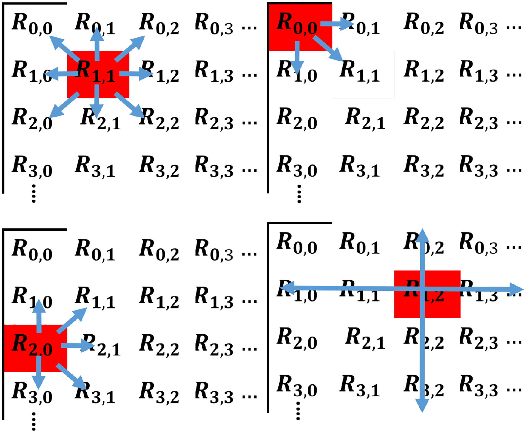
This section discusses the strategy of sequencing the reference points generated so that the hTetro robot follows the order as a roadmap. In order to sequence the generated reference points, we are using a technique which is based on the grid-based wavefront algorithm. 13 In this algorithm, we are using the WP array as an input wherein we get the initial reference point. Further, we are using the R value from the matrix Mt to complete this process. Altogether we are arranging the series of R values, and it represents Q values. The algorithm assumes that the initial value of R is 1 and its corresponding Q values as a default starting point for the hTetro robot. Once we have the initial reference element, concerning that item, the algorithm looks for the smallest R value in the neighboring elements. So the algorithm performs a R value comparison between every neighboring element. The current reference location can determine the total set of R values that are compared. The proposed algorithm undergoes three different searching methods, namely middle search, corner search, and edge search, to identify the smallest neighboring R value as shown in the upper-left, upper-right, and bottom-left sub-figures in Figure 13, respectively. A different number of grids will be checked for the three searching strategies: three grids during an edge search, five in a corner search, and eight while a middle search is performed. The algorithm to find the nearby grid is shown in Algorithm 3. In the algorithm, the searching method will push all possible nearby grids into a grid array G. Once the corresponding reference of neighbor grids are visited, the algorithm will proceed on to a row–column search which is as depicted in the bottom-right sub-figure in Figure 13. The system starts the search from the current grid location and spreads to horizontal and vertical directions until it founds a valid grid cell whose reference coordinate has yet been visited.
Different search techniques to identify the next R value.
Tiling motion sequencing of generated waypoints.


Once the grid array G has all feasible grids listed, the algorithm will proceed a simple loop function which will find the reference coordinate in the array that holds the smallest R value. The chosen reference coordinate will then be pushed to the tiling motion waypoint array
Navigation strategy
Given a sequenced robot
hTetro route generation strategy.


In the developed navigation strategy, we refer to the connection between every waypoint pairs as “paths,” while we call the connection between all paths “route.” In Algorithm 4, we generate paths using function
In function
Finally, the function
Evaluation of tiling motion
As part of this study, we have evaluated the proposed motion planning on the hTetro robot in a simulated environment. In order to analyze the performance of the proposed motion planning algorithm, we will compare the results with several algorithms that tackle the waypoint sequencing as well. The simulator adopts all the algorithms to guide the robot navigation within the workspace. For algorithms, 37 we directly adopt into the simulator without making any adjustments to the algorithm. The simulations are conducted using MATLAB Simulink software.
This section will firstly introduce the six path planning strategies that we have selected as our benchmarking algorithms. The evaluation criteria will then be introduced. Finally, the workspace setups under three scenarios, and the navigation results in these scenarios will be presented.
Benchmarking path planning strategies
In order to accomplish CPP tasks, many algorithms have been proposed for robots with a single fixed morphology, each of which is constructed based on a specific cellular decomposition method. Among all path planning algorithms that adopted the grid-based cellular decomposition technique, zigzag path (or boustrophedon path) and spiral path are the two popular navigation strategies for the robot to accomplish area coverage. The conventional zigzag path algorithm explores the area with a constant sweeping width and performs a 180° turn when an obstacle is encountered and move on to the next sweeping lane to avoid the swept areas. While the conventional spiral path algorithm works under a similar framework, where the robot performs 90° turns in a fixed direction when an obstacle is presented or when the robot enters areas that have already been covered, resulting in a spiral-shaped navigation path with diminishing width as time goes on. Both algorithms are capable of producing effective results in terms of minimizing the amount of area revisited by the robot platform.
Nevertheless, unlike the proposed motion planning algorithm which makes use of waypoint sequencing to navigate within the workspace, the conventional zigzag and spiral algorithms do not guarantee complete coverage of the entire area, so minor adjustments to the existing conventional zigzag and spiral path algorithms have to be made for our hTetro robot simulation model in order to make meaningful comparison between different navigation strategies. To achieve this goal, we make use of the unsequenced waypoint array WP that was created previously and produce different sequencing patterns for robot navigation. In this article, a total of eight benchmarking algorithms are introduced: conventional zigzag algorithm, conventional spiral algorithms, and six different sequencing patterns generated based on the generated waypoint array, including random path algorithm, greedy path algorithm, two zigzag-pattern-based algorithms, and two spiral-pattern-based algorithms.
Here we adopt a greedy search
38
and random search algorithms
37
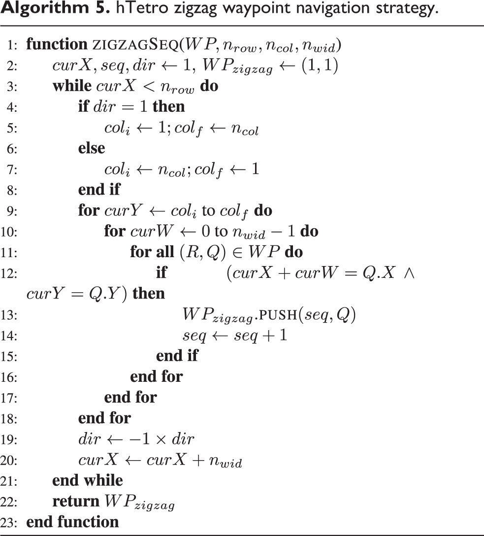
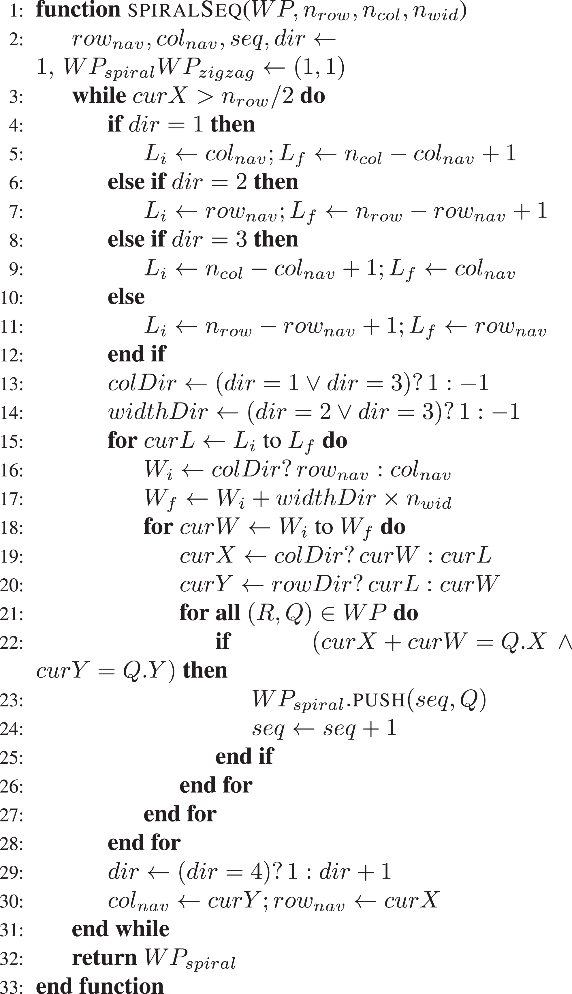
directly into our model without making any adjustments to the algorithm. From the starting point, the greedy search algorithm will continuously explore the workspace and assign the nearest configuration like the following waypoint, while the random search assigns the next waypoint from the unsequenced waypoint set at random. The zigzag-pattern- and spiral-pattern-based algorithm are being described in Algorithms 5 and 6, respectively. These modified algorithms now take the unsequenced waypoint series WP and a sweeping width
hTetro zigzag waypoint navigation strategy.

hTetro spiral waypoint navigation strategy.

Evaluation criteria
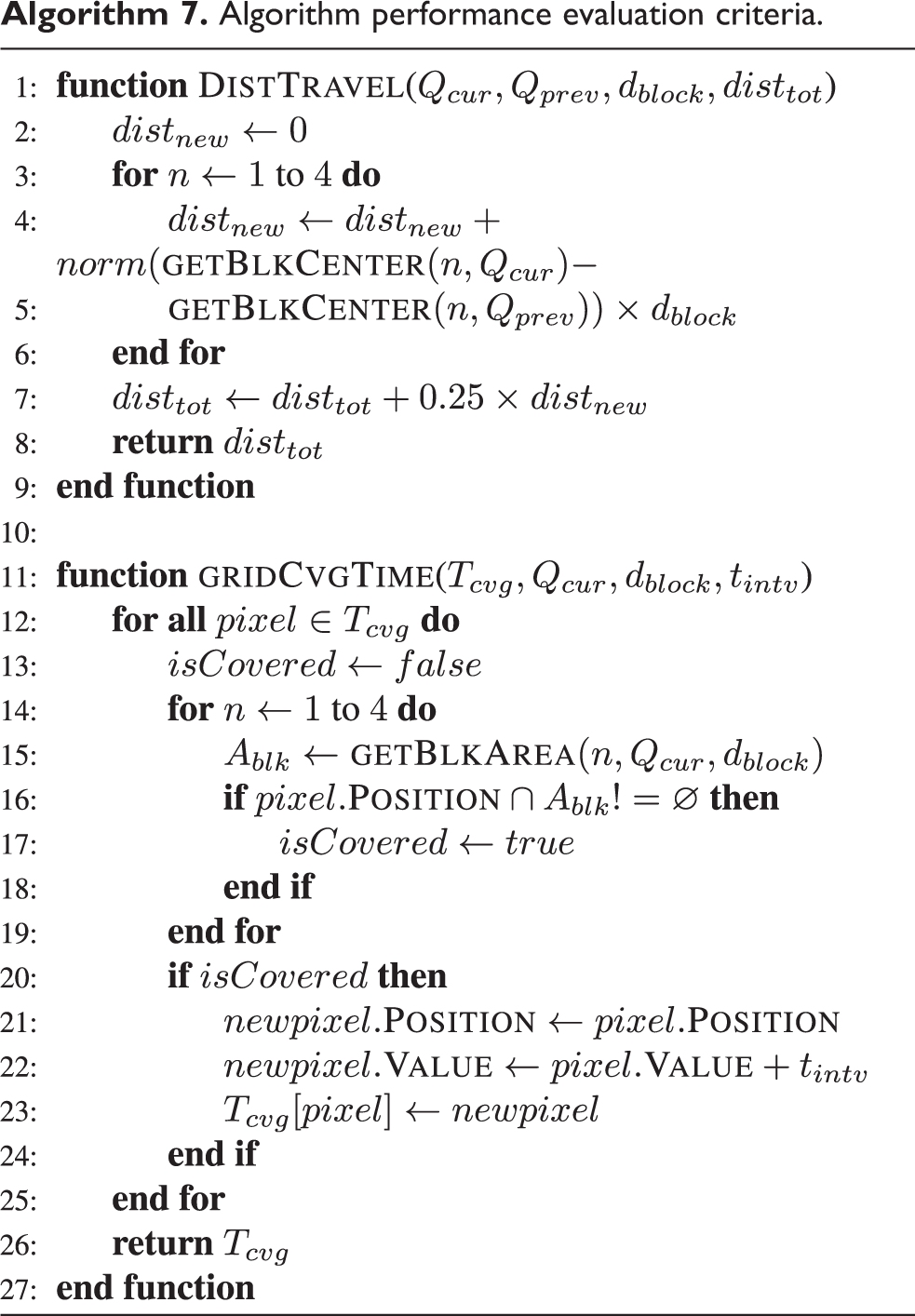
We propose two evaluation criteria to find the most efficient algorithm: average distance traveled and average grid coverage time. Both criteria are presented in Algorithm 7. Average distance traveled is determined based on the trajectories of all four hTetro blocks during the navigation process. In the algorithm, the distance traveled by each hTetro block within every time instance will be calculated and stored in
Algorithm performance evaluation criteria.

Experiments with the proposed technique
In this experiment, a total of three scenarios are being tested to analyze the performance of the algorithms. The workspace of these scenarios is being illustrated in Figure 14. Scenario 1 illustrates an empty workspace of

Workspace map of the three evaluation scenarios. (a) Scenario 1, (b) Scenario 2, and (c) Scenario 3.
With the grid map created, the simulator runs the global tiling set algorithm as described in the fourth section to tile the grid space. The matrix Mt
is being created for each scenario according to the algorithm. Elements in these matrices will hold a negative value of

Tiled matrices Mt in the three scenarios. (a) Scenario 1, (b) Scenario 2, and (c) Scenario 3.
The completion of the tile matrices leads the simulator to generate the reference points for each tile pieces as described in the fifth section, with the results shown in Figure 16. Once the unsequenced waypoint arrays

Generated reference coordinates in the three scenarios. (a) Scenario 1, (b) Scenario 2, and (c) Scenario 3.

Produced navigation paths in the three scenarios. (a) Scenario 1, (b) Scenario 2, and (c) Scenario 3.
Experimental setups
As part of this research, we conducted experimental studies to validate the proposed tiling motion with the hTetro robot under the mentioned scenarios. The first experiment tested Scenario 1, wherein the test area consisted of a rectangular plot of 250 cm × 250 cm (Figure 18). Similarly, we chose an area of 275 cm × 275 cm and 350 cm × 275 cm for Scenario 2 and Scenario 3, respectively. We placed the obstacles inside the test area of Scenarios 1 and 2, as illustrated in the workspace map. The experimental setup consisted of a predefined floor area with a boundary construed by 5 mm thick foam sheet walls with a height of 40 cm. The boundaries of the defined area were adjusted according to the workspace scenarios. We housed an overhead image-acquisition device to record the area coverage process to calculate the percentage area recovered by the hTetro robot during the experimental trials. The imaging device was mounted in such a way to cover the entire workspace, as shown in Figure 18. The resulting raw video files were post-processed to analyze the performance of the robot. From the image, it can be seen that the frame contains perspective distortion. It is difficult to track the robot when the perspective of the camera is a bit slanted. So, we used a perspective distortion elimination algorithm 39 to track the robot in every frame and generate a coverage map. We pasted red color paper on top of each block of the hTetro that aids in tracking. After we identify the red blobs in every frame, we identify the centroid of the red regions. For each identified centroids, green-colored squares are plotted in a clear reference image. Whenever the detected centroids enter the covered area, the algorithm would plot lighter red squares instead of green for that particular centroid. So in a coverage map, if there are darker red regions, means the robot visited that particular place more frequently. After generating the coverage maps on the reference images, the percentage of the area recovered was calculated using equation (3). The video post-processing and generation coverage map were executed in Matlab 2017 software
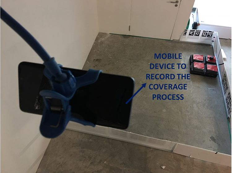
Image acquisition device and experimental test bed.

where
Results
Simulated results
During the navigation process, the average distance traveled and the grid coverage time is consistently calculated through Algorithm 7.
Based on the values calculated, bar charts are being plotted to compare the results between each algorithm, which is as shown in Figures 19 and 20. In Figure 19, the average grid coverage time in all three scenarios are presented. All algorithms demonstrate better performance in Scenario 1 since it is an obstacle-free environment, and areas are less likely to be revisited. With
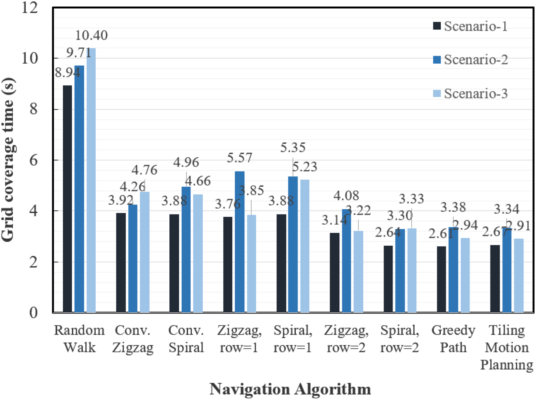
The grid coverage time comparison between the nine algorithms under Scenarios 1 to 3.

The average distance travelled comparison between the nine algorithms under Scenarios 1 to 3.
To gain a better understanding of the navigation paths taken by each algorithm and how they pose influences in the performance of the algorithm, we create robot coverage heat maps to visualize the data better. A robot coverage heat map is created once the navigation process terminates and is constructed based on the final coverage values stored in

Coverage heat map in Scenario 1. (a) Random path. (b) Conventional zigzag pattern. (c) Conventional spiral pattern. (d) Zigzag pattern

Coverage heat map in Scenario 2. (a) Random path. (b) Conventional zigzag pattern. (c) Conventional spiral pattern. (d) Zigzag pattern

Coverage heat map in Scenario 3. (a) Random path. (b) Conventional zigzag pattern. (c) Conventional spiral pattern. (d) Zigzag pattern
Experimental results
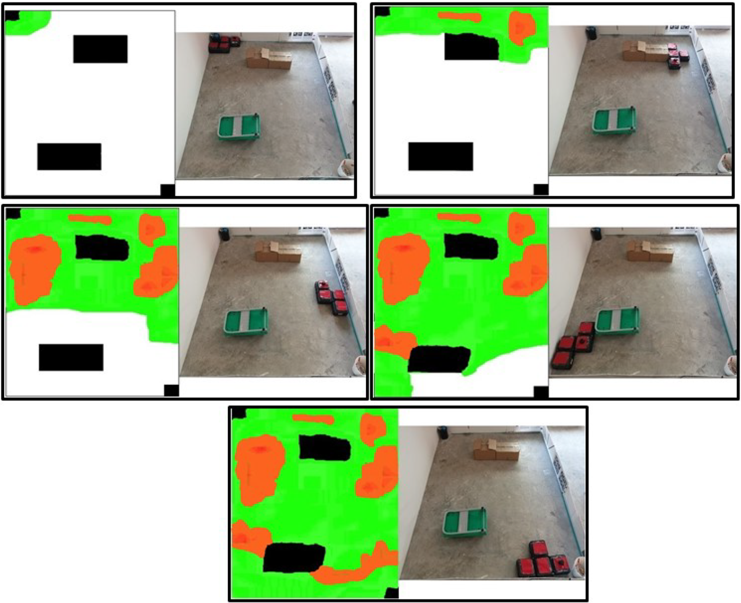
Before each experimental run, the hTetro robot was placed in a predefined starting point within the test area. The robot uses a hector SLAM 40 technique to localize inside the workspace and navigates accurately on the waypoints. The coverage motion of the hTetro robot was recorded while experimenting. At the end of each experimental run, the image-processing algorithm mentioned in the previous section was used to process the recorded videos to produce the robot coverage map, and its respected area recovered values. Figure 24 illustrates the robot tracked map with hTetro, which was generated from the video recorded from the experiment validating the first scenario. In the image, the green shaded pixels represent the area tiled by the hTetro, and the red shaded parts show area recovered. Figure 24 contains five set of images, two in each set that represents the hTetro robot’s tiling motion at the various time point of the experiment validating Scenario 1. In each set of images, the even pictures represent the hTetro robot’s position at a particular time point, and the odd picture indicates hTetro coverage map at the same instant. Similar set of images for the experimental Scenarios 2 and 4 are illustrated in Figures 25 and 26. Similarly, the coverage map for other algorithm under all three scenarios is shown in Figures 27 to 29.

Coverage map for tiling motion in Scenario 1.
Coverage map for tiling motion in Scenario 2.

Coverage map for tiling motion in Scenario 3.

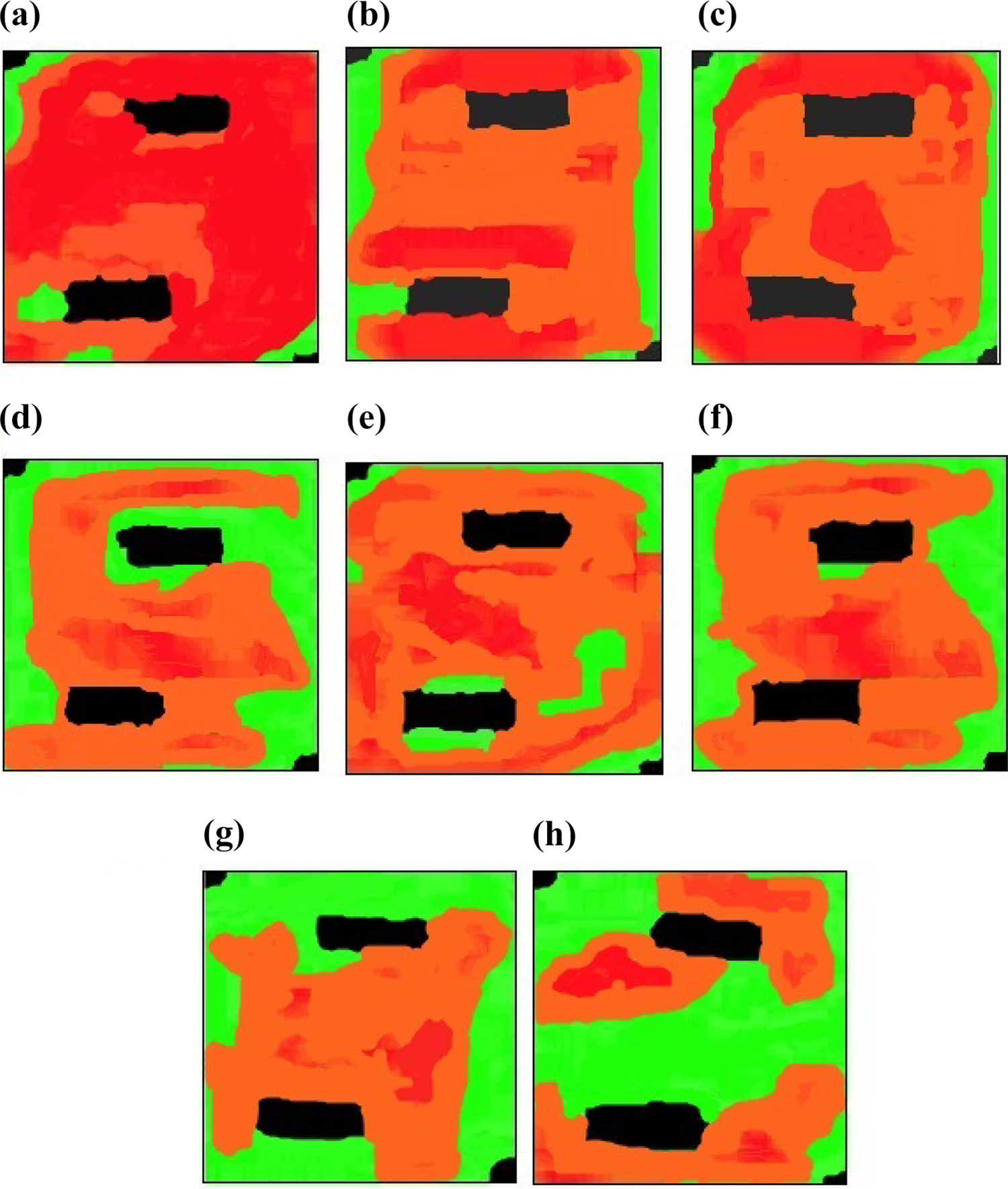
Coverage map for other algorithms in Scenario 1. (a) Random path. (b) Conventional zigzag. (c) Conventional spiral. (d) Zigzag pattern

Coverage map for other algorithms in Scenario 2. (a) Random path. (b) Conventional zigzag. (c) Conventional spiral. (d) Zigzag pattern
Coverage map for other algorithms in Scenario 3. (a) Random path. (b) Conventional zigzag. (c) Conventional spiral. (d) Zigzag pattern
Discussion
In this section, we discuss the advantage of our proposed motion planning technique for the hTetro robot by comparing with other path planning algorithms.
In the case of conventional zigzag and spiral algorithms, the hTetro robot maintains as a fixed O-shape (default Morphology) and attempts to cover the entire workspace. The coverage performance of these algorithms is similar to waypoint-based zigzag- and spiral-pattern algorithms with
In both waypoints-based zigzag- and spiral-pattern algorithms, the robot follows the designated path to navigate within the environment. The advantage of these algorithms is similar to conventional zigzag and spiral algorithms, which provides a straightforward method to perform the coverage task within the designated space. These algorithms tend to perform consistent results in larger maps since the performance is less likely to be affected by one or a few unsequenced waypoints within the workspace. The introduction of the revised zigzag and spiral algorithms (based on Algorithms 5 and 6) ensures that the entire area coverage can be achieved. Figures 21(d) to (g), 22(d) to (g), and 23(d) to (g) all demonstrate that by increasing the navigation width from
The random path algorithm, though being able to successfully cover the entire workspace, has shown to be an overall ineffective navigation strategy since the robot is constantly revisiting several grids in the workspace due to the randomly chosen waypoint sequence, which results in the highest average coverage time and the longest distance travelled among all seven algorithms in all scenarios.
The greedy search algorithm generally performs well with a small sample size of waypoint sequences. Nevertheless, the greedy search algorithm gets punished by leaving several of the suboptimal waypoints behind during the navigation process. If a few waypoints are being ignored during the sequencing process, the robot has to travel a much longer distance to cover these waypoints at the end of the navigation process. The greedy algorithm also faces some issues when obstacles are being introduced on the map. In Figure 23(h), the bottom-left corner has been revisited multiple times compared to the results in Figure 23(g) and (i). This is due to an unwise selection of the navigation route in the greedy algorithm that guides the robot to navigate from one side of the bottom-left obstacle in Scenario 3 to the other side (since it is the closest waypoint that can be discovered), resulting in undesirable average grid coverage time around obstacles. Also, the greedy search algorithm takes more running time to complete the path generation for the generated waypoint which is undoubtedly larger than the previous algorithms. Table 1 provided the numerical comparison for path generation of different coverage method in three scenarios. It is worth to note that zigzag and spiral methods connect the predefined waypoint orderly; on the other hand, random search and greedy search depend on the number of trials to find an optimal solution. Due to this reason, the conventional algorithms have lesser path generation time than the greedy and random search.
Comparison of path generation time for all considered coverage algorithms.

On the other hand, the proposed tiling motion planning algorithm has demonstrated a great performance with the shortest distance traveled and decent time grid coverage time compared to the other algorithms in the three scenarios presented as shown in both Figures 19 and 20. The grid coverage heat maps shows that the proposed algorithm might face some difficulties navigating through narrow spaces (as shown in the red-colored area in Figure 23(i)) but performs well in workspaces with large and empty areas as illustrated in Figures 21(i) and 23(i). When it comes to path generation time, the proposed motion planning technique took slightly more time than traditional zigzag and spiral with least recover area, but significantly lower than random search and greedy search.
Concerning the experimental trials, the total area recovered for the generated coverage map for all considered path planning algorithms for every scenario is shown as a trend in Figure 30. In the coverage map (Figures 27
to 29), the red regions indicate the area that was recovered by the robot, and the green region is the area with no overlaps. The percentage of area recovered was computed from the coverage map using the equation (3). The percentage of area recovered from the coverage map, and the grid coverage time from the heat map was computed differently. Due to this reason, the values from both trials will differ very much and cannot be compared. However, in the discussion below, we are going to compare the red regions generated between grid time map and coverage map. On the other hand, from the coverage map images, we can notice there are some overlapping regions on the obstacles which are caused due to the robot position mismatch during the tracking process. All most every experimental trial and its corresponding results were supporting our previous arguments on simulated outcomes. For instance, the coverage map that was generated for both conventional zigzag and spiral motion contains more than 90% of the red region in all considered scenarios, which is almost equal to the simulations. Also, in the experimental trials, the robot cannot reaches the narrow space in Scenario 2, as shown in Figure 31. The experimental trials that concern the waypoint-based zigzag and spiral motions produce more area recoverage regions in the coverage map. The total area of the red region in the coverage map for zigzag and spiral pattern
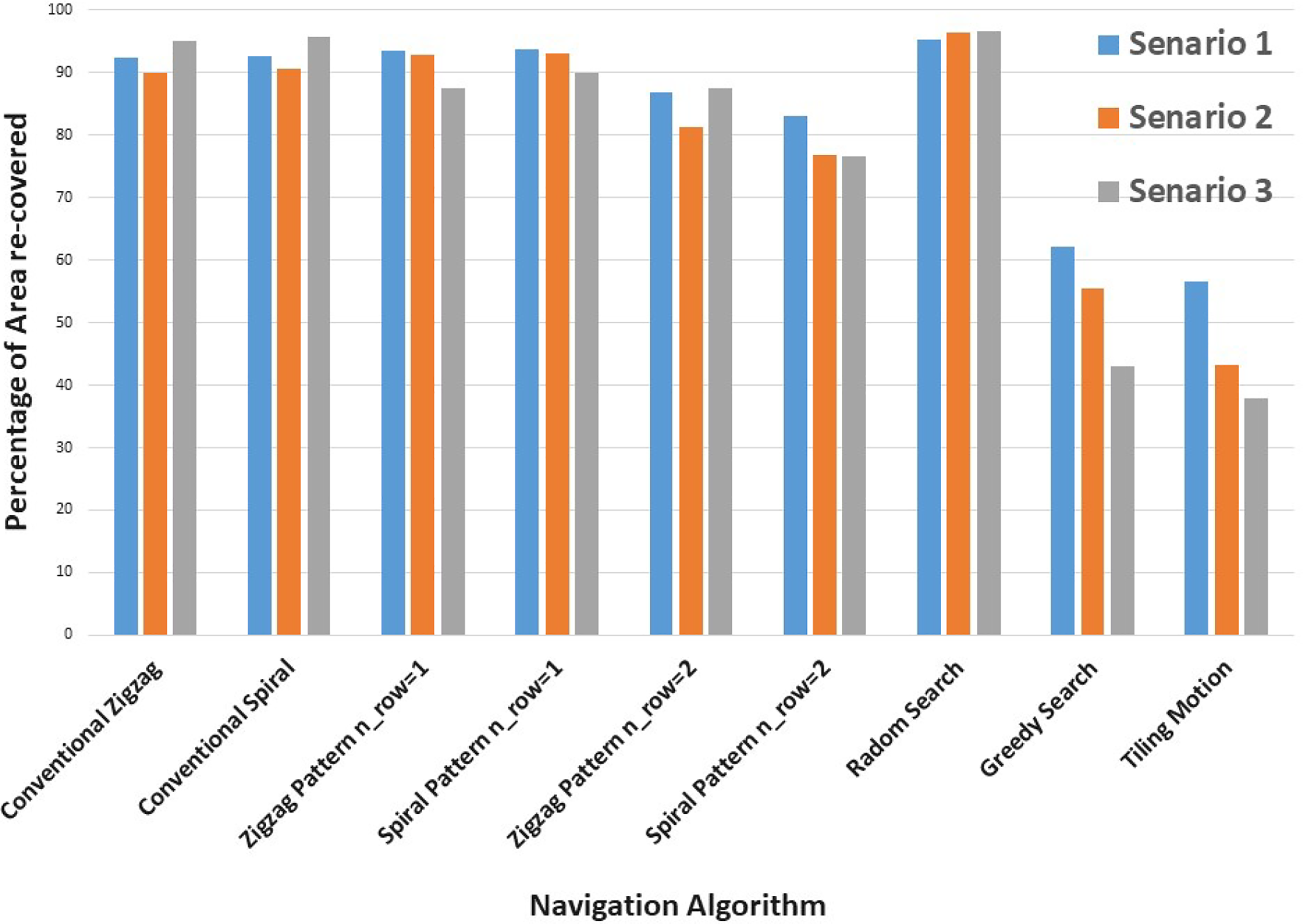
Percentage of area recovered by hTetro in all considered experimental scenarios with different coverage motion techniques.

Robot failed to access the narrow space while performing traditional coverage motion.
Conclusion
This article introduced a motion planning technique to achieve maximum area coverage in a Tetris-inspired shape-shifting robotic floor cleaner named hTetro that was based on the polyomino tiling theory. We discussed an autonomous tile-set generation based on the tiling theory concept and introduced the path generation for the hTetro robot to navigate on the generated tiling set with an objective of maximizing the area coverage. We validated the proposed algorithm by benchmarking its performance with traditional CPP techniques under three different scenarios. We first conducted simulated trials for all considered algorithms. At the end of the trials, the waypoint navigation map and the coverage heat map are being generated, which illustrates the total area recovered by the robot under different coverage algorithms. Also, we conducted real-time experiments in a fixed setting that replicates the scenarios. In each experiment, the robot cleared the sequenced waypoints while assuming its morphology at each point. We tracked the robot motion using an overhead camera in order to generate a coverage map to compute the total area recovered for each experimental case. Both simulation and experimental results establish that the proposed tiling motion technique achieves maximum coverage area with the less recovered area.
Future research work is set to focus on the following areas: (1) Optimizing the reference point generation; (2) the tile-set generation with respect to energy cost in order to reduce the number of reconfiguration to complete the full area coverage; (3) studying locomotion with trajectory tracking and following while performing the tiling motion on the generated tile-set; (4) implementing the proposed approach for other polyforms reconfigurable robots; (5) applying tiling theory under the cellular decomposition technique where we apply different tiling theory for each decomposed cell in a complex environment; and (6) studying long-term autonomy with the tiling motion on a physical hTetro platform.
Footnotes
Declaration of conflicting interests
The author(s) declared no potential conflicts of interest with respect to the research, authorship, and/or publication of this article.
Funding
The author(s) disclosed receipt of the following financial support for the research, authorship, and/or publication of this article: This research is supported by the National Robotics R&D Programme Office, Singapore under its grant RGAST1907 and administered by the Agency for Science, Technology and Research.